EP0266767A2 - Agencement permettant l'introduction d'air extérieur pour la ventilation et/ou la climatisation d'une voiture automobile - Google Patents
Agencement permettant l'introduction d'air extérieur pour la ventilation et/ou la climatisation d'une voiture automobile Download PDFInfo
- Publication number
- EP0266767A2 EP0266767A2 EP87116308A EP87116308A EP0266767A2 EP 0266767 A2 EP0266767 A2 EP 0266767A2 EP 87116308 A EP87116308 A EP 87116308A EP 87116308 A EP87116308 A EP 87116308A EP 0266767 A2 EP0266767 A2 EP 0266767A2
- Authority
- EP
- European Patent Office
- Prior art keywords
- air
- fresh air
- arrangement
- air conditioning
- duct
- Prior art date
- Legal status (The legal status is an assumption and is not a legal conclusion. Google has not performed a legal analysis and makes no representation as to the accuracy of the status listed.)
- Withdrawn
Links
Images


Classifications
-
- B—PERFORMING OPERATIONS; TRANSPORTING
- B60—VEHICLES IN GENERAL
- B60H—ARRANGEMENTS OF HEATING, COOLING, VENTILATING OR OTHER AIR-TREATING DEVICES SPECIALLY ADAPTED FOR PASSENGER OR GOODS SPACES OF VEHICLES
- B60H1/00—Heating, cooling or ventilating devices
- B60H1/00507—Details, e.g. mounting arrangements, desaeration devices
- B60H1/00557—Details of ducts or cables
- B60H1/00564—Details of ducts or cables of air ducts
-
- B—PERFORMING OPERATIONS; TRANSPORTING
- B60—VEHICLES IN GENERAL
- B60H—ARRANGEMENTS OF HEATING, COOLING, VENTILATING OR OTHER AIR-TREATING DEVICES SPECIALLY ADAPTED FOR PASSENGER OR GOODS SPACES OF VEHICLES
- B60H1/00—Heating, cooling or ventilating devices
- B60H1/00507—Details, e.g. mounting arrangements, desaeration devices
- B60H1/00514—Details of air conditioning housings
- B60H1/0055—Details of air conditioning housings the housing or parts thereof being integrated in other devices, e.g. dashboard
-
- B—PERFORMING OPERATIONS; TRANSPORTING
- B60—VEHICLES IN GENERAL
- B60H—ARRANGEMENTS OF HEATING, COOLING, VENTILATING OR OTHER AIR-TREATING DEVICES SPECIALLY ADAPTED FOR PASSENGER OR GOODS SPACES OF VEHICLES
- B60H1/00—Heating, cooling or ventilating devices
- B60H1/24—Ventilating devices where the heating or cooling is irrelevant
- B60H1/241—Ventilating devices where the heating or cooling is irrelevant characterised by the location of ventilation devices in the vehicle
- B60H1/242—Ventilating devices where the heating or cooling is irrelevant characterised by the location of ventilation devices in the vehicle located in the front area
-
- B—PERFORMING OPERATIONS; TRANSPORTING
- B60—VEHICLES IN GENERAL
- B60H—ARRANGEMENTS OF HEATING, COOLING, VENTILATING OR OTHER AIR-TREATING DEVICES SPECIALLY ADAPTED FOR PASSENGER OR GOODS SPACES OF VEHICLES
- B60H1/00—Heating, cooling or ventilating devices
- B60H1/24—Ventilating devices where the heating or cooling is irrelevant
- B60H1/26—Ventilating openings in vehicle exterior; Ducts for conveying ventilating air
-
- B—PERFORMING OPERATIONS; TRANSPORTING
- B62—LAND VEHICLES FOR TRAVELLING OTHERWISE THAN ON RAILS
- B62D—MOTOR VEHICLES; TRAILERS
- B62D21/00—Understructures, i.e. chassis frame on which a vehicle body may be mounted
- B62D21/17—Understructures, i.e. chassis frame on which a vehicle body may be mounted forming fluid or electrical conduit means or having other means to accommodate the transmission of a force or signal
Definitions
- the invention relates to an arrangement for fresh air supply for the ventilation and / or air conditioning of a passenger car with body support columns.
- the supply of fresh air for the ventilation or air conditioning of the interior takes place in known passenger cars in different ways.
- an air duct provided with a grille opens between the windshield and the adjoining front hood.
- Another arrangement is shown in the generic DE-OS 30 24 988, where air inlet gaps are provided in the area of the side bonnet separating joint, which open into a separate air duct.
- That solution has the advantage over the first-mentioned arrangement that the air duct can be made larger, since in the side area of the vehicle - in contrast to the lower windshield area, in which the instrument panel and the combustion engine are arranged close to one another - there is more space available.
- both known arrangements have the disadvantage that a separate air duct must be provided for the fresh air supply. That channel is the through in a complex manner Adapt bodywork or other components to the available space.
- the object of the invention is to show a simplified arrangement for the supply of fresh air in terms of construction costs. This object is achieved by the characterizing features of the first claim.
- a further, separate air duct can be omitted without replacement.
- Particularly suitable - but not limited to that embodiment - is the A pillar of a passenger car body.
- part of the wheel house bulkhead plate can advantageously be omitted by appropriate shaping.
- the sheet metal parts forming the fresh air guide channel can also directly connect, for example, to the spring cup of the front wheel suspension.
- That arrangement according to the invention also has the advantage that the fresh air guide duct has a larger cross section than conventional duct designs. A consequence of this is a reduction in the air flow resistance; With the arrangement according to the invention, therefore, larger fresh air masses can be guided.
- An embodiment according to claim 2 is particularly advantageous when the inlet opening of the fresh air guide channel is in the region of the upper end of the spring cup. That area is mostly from the ge closed vehicle front hood or in a more general form covered by a movable outer body part, so that the fresh air guide channel does not stand in the way of stylistic requirements.
- the function of the fresh air intake is carried out by an air duct provided in the front hood of the vehicle, which in turn opens on the outside of the body.
- a seal is provided between the inlet opening of the fresh air guide duct and the air duct provided in the front hood (bonnet). Intake air is thus supplied through or within the vehicle bonnet.
- an air filter element is provided in the fresh air guide duct and / or in the air duct of the movable outer body part, then this - particularly in the case of an embodiment according to claim 2 - is particularly easy to replace.
- the front cover has to be opened, after which such a filter element can be freely accessible if it is arranged accordingly.
- a filter element be it a conventional air filter or an activated carbon filter, is only particularly effective and has a desirable low flow resistance if the cross-section through which the flow passes can be kept as large as possible.
- Such a design is, however, readily possible with a corresponding design of the body support column.
- Claims 4 and 5 advantageously further develop a fresh air guide duct according to the invention and a heating / air conditioning unit usually connected to it.
- the air conditioner on everyone today common passenger cars is centrally located below the dashboard, it is now also in the body support column or in a body side panel. Since the components provided in an air conditioning unit, such as blowers, heating heat exchangers and air conditioning evaporators, not only require a corresponding amount of installation space, but also have a weight that should not be underestimated and thus significantly impair the center of gravity of the passenger car, the known air conditioning unit arrangement is disadvantageous, however .
- the heating / air conditioning unit when arranged in a body side panel as well as in a body support column, it is possible to provide the heating / air conditioning unit practically as deep as possible at the level of the body floor, which is known in the case of a known central arrangement below the dashboard due to the fact that it is also centered and opposite the gearbox tunnel, which runs at an elevated level, is excluded.
- the two specified arrangements also offer the advantage that the heating / air-conditioning unit is located in a previously unused room outside the operating area of the vehicle driver. This creates an additional space previously used by the heating / air conditioning unit for the attachment of important operating or display elements, which from an ergonomic point of view are now more clearly in the driver's passenger's field of vision or can be made more spacious again.
- Another advantage is that this arrangement enables the use of larger blower units. In order to achieve the required air throughput, the fan speed can thus be reduced and the interior noise level reduced.
- Claim 6 describes a car with two heating / air conditioning units for separately controllable air conditioning, for example the left and right half of the vehicle.
- an arrangement according to the invention for the supply of fresh air for ventilation or air conditioning is particularly advantageous, since the advantages which can be achieved thereby appear twice.
- An air conditioning unit 2 is arranged in the front side area of a car body designated as a whole by 1.
- the body shell is according to the The representation in the left half of FIG. 2 or in FIG. 4 has been modified compared to a conventionally constructed body frame 3, as shown in the right half of FIG. 2 or in FIG. 3.
- This change is particularly clear for the A-pillar constructed from sheets 4 and 7.
- the A-pillar outer panel 4 is widened downwards from the center of the vehicle and advanced to the wheel house 5 or the front spring cup 6.
- the A-pillar inner panel 7 is designed similarly and is provided with an opening 8 in the footwell area for mounting the air conditioning unit 2.
- the two A-pillar sheets 4 and 7 thus form not only a sufficient space for accommodating the air conditioning unit 2, but also the fresh air guide duct 9 designed according to the invention. A separate, previously customary fresh air guide duct can thus be dispensed with.
- the air conditioner 2 which is already preassembled and is rubber-mounted in the body, is provided with a plurality of air outlet openings 16 and a blower motor 17.
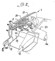
- On the air outlet openings 16 is an air distribution unit 18, consists of a plurality of air guiding channels 18a to 18f. This is shown in Fig. 5, wherein the air conditioner 2 is connected by means of a cover plate 19.
- the air duct 18f is advantageously arranged in the interior of the door sill 12 for air conditioning the vehicle Fonraum 15.
- the air flow which is improved in comparison to the prior art, since it runs in a straight line, enables a significantly increased effect in the rear room ventilation.
- FIG. 5 shows details of the fresh air guide channel 9. It is covered with an air filter element 20, which is easy to replace due to its arrangement.
- a circumferential seal 21 at the inlet opening of the fresh air guide channel 9 connects airtightly to the inner surface of the vehicle front hood, not shown, so that the air supply from a outer suction point.
- the seal 21 prevents the penetration of vapors from the engine compartment covered by the bonnet.
- the fresh air guide channel 9 has a plurality of openings 22 through which lines for supplying the air conditioning unit with a heat transfer medium are laid.
- the present invention is also particularly suitable for arranging two fresh air guide ducts provided for the left and right vehicle areas to form separately controllable air conditioning units.
- the advantages of simple training, the lowered center of gravity, and the Space savings then appear even more clearly.
Landscapes
- Engineering & Computer Science (AREA)
- Mechanical Engineering (AREA)
- Physics & Mathematics (AREA)
- Thermal Sciences (AREA)
- Chemical & Material Sciences (AREA)
- Combustion & Propulsion (AREA)
- Transportation (AREA)
- Air-Conditioning For Vehicles (AREA)
Applications Claiming Priority (2)
| Application Number | Priority Date | Filing Date | Title |
|---|---|---|---|
| DE19863637773 DE3637773A1 (de) | 1986-11-06 | 1986-11-06 | Karosserie eines personenkraftwagens mit mindestens einem heiz-/klimageraet |
| DE3637773 | 1986-11-06 |
Publications (2)
| Publication Number | Publication Date |
|---|---|
| EP0266767A2 true EP0266767A2 (fr) | 1988-05-11 |
| EP0266767A3 EP0266767A3 (fr) | 1989-05-31 |
Family
ID=6313274
Family Applications (1)
| Application Number | Title | Priority Date | Filing Date |
|---|---|---|---|
| EP87116308A Withdrawn EP0266767A3 (fr) | 1986-11-06 | 1987-11-05 | Agencement permettant l'introduction d'air extérieur pour la ventilation et/ou la climatisation d'une voiture automobile |
Country Status (2)
| Country | Link |
|---|---|
| EP (1) | EP0266767A3 (fr) |
| DE (1) | DE3637773A1 (fr) |
Cited By (6)
| Publication number | Priority date | Publication date | Assignee | Title |
|---|---|---|---|---|
| WO1992011167A1 (fr) * | 1990-12-20 | 1992-07-09 | Audi Ag | Carrosserie de voiture privee avec un logement pour composants electroniques |
| EP0739800A1 (fr) * | 1995-04-27 | 1996-10-30 | INSTITUT FÜR SCHIENENFAHRZEUGE GmbH | Configuration de la caisse notamment pour voitures ferroviaires |
| EP0962342A3 (fr) * | 1998-06-03 | 2002-07-31 | Ohtsuka Co., Ltd. | Conduit d'aération à absorption d'énergie de choc |
| EP0846580A3 (fr) * | 1996-12-07 | 2002-11-27 | Bayerische Motoren Werke Aktiengesellschaft, Patentabteilung AJ-3 | Dispositif de chauffage et de ventilation pour une voiture, et indépendante du véhicule automobile, notamment pour voitures particulières |
| EP1705048A3 (fr) * | 2005-03-26 | 2007-09-19 | Dr.Ing. h.c.F. Porsche Aktiengesellschaft | Dispositif de joint d'étanchéité pour un conduit de ventilation |
| DE102007029859A1 (de) | 2007-06-28 | 2009-01-08 | GM Global Technology Operations, Inc., Detroit | Pkw-Rohkarosserie |
Families Citing this family (3)
| Publication number | Priority date | Publication date | Assignee | Title |
|---|---|---|---|---|
| DE102011115170A1 (de) | 2011-09-27 | 2012-04-05 | Daimler Ag | Kraftfahrzeug mit einem Heiz-/Klimagerät |
| DE102016224920B4 (de) * | 2016-12-14 | 2023-10-05 | Bayerische Motoren Werke Aktiengesellschaft | Vorrichtung zur Klimatisierung und/oder zum Heizen eines Kraftfahrzeuginnenraumes |
| DE102017202504B4 (de) | 2017-02-16 | 2019-09-05 | Audi Ag | Zusatzheizung für ein Fahrzeug |
Family Cites Families (7)
| Publication number | Priority date | Publication date | Assignee | Title |
|---|---|---|---|---|
| FR1387184A (fr) * | 1963-12-13 | 1965-01-29 | Renault | Perfectionnements à la climatisation des véhicules automobiles |
| FR1398105A (fr) * | 1964-03-26 | 1965-05-07 | Renault | Perfectionnements aux installations de climatisation pour véhicules automobiles |
| DE6922505U (de) * | 1969-06-06 | 1969-10-09 | Celjabinskij Traktornyj Zd | Kabine fuer den fahrer eines transportmittels |
| DE1939434A1 (de) * | 1969-08-02 | 1971-02-11 | Daimler Benz Ag | Einrichtung zur Klimatisierung von Fahrzeuginnenraeumen |
| US4120527A (en) * | 1977-04-15 | 1978-10-17 | Caterpillar Tractor Co. | Cab design |
| JPS55165875U (fr) * | 1979-05-16 | 1980-11-28 | ||
| JPS60197423A (ja) * | 1984-03-21 | 1985-10-05 | Nissan Motor Co Ltd | 自動車の換気構造 |
-
1986
- 1986-11-06 DE DE19863637773 patent/DE3637773A1/de not_active Withdrawn
-
1987
- 1987-11-05 EP EP87116308A patent/EP0266767A3/fr not_active Withdrawn
Cited By (7)
| Publication number | Priority date | Publication date | Assignee | Title |
|---|---|---|---|---|
| WO1992011167A1 (fr) * | 1990-12-20 | 1992-07-09 | Audi Ag | Carrosserie de voiture privee avec un logement pour composants electroniques |
| US5417471A (en) * | 1990-12-20 | 1995-05-23 | Audi Ag | Bodywork of a passenger car with an electronics housing |
| EP0739800A1 (fr) * | 1995-04-27 | 1996-10-30 | INSTITUT FÜR SCHIENENFAHRZEUGE GmbH | Configuration de la caisse notamment pour voitures ferroviaires |
| EP0846580A3 (fr) * | 1996-12-07 | 2002-11-27 | Bayerische Motoren Werke Aktiengesellschaft, Patentabteilung AJ-3 | Dispositif de chauffage et de ventilation pour une voiture, et indépendante du véhicule automobile, notamment pour voitures particulières |
| EP0962342A3 (fr) * | 1998-06-03 | 2002-07-31 | Ohtsuka Co., Ltd. | Conduit d'aération à absorption d'énergie de choc |
| EP1705048A3 (fr) * | 2005-03-26 | 2007-09-19 | Dr.Ing. h.c.F. Porsche Aktiengesellschaft | Dispositif de joint d'étanchéité pour un conduit de ventilation |
| DE102007029859A1 (de) | 2007-06-28 | 2009-01-08 | GM Global Technology Operations, Inc., Detroit | Pkw-Rohkarosserie |
Also Published As
| Publication number | Publication date |
|---|---|
| DE3637773A1 (de) | 1988-05-11 |
| EP0266767A3 (fr) | 1989-05-31 |
Similar Documents
| Publication | Publication Date | Title |
|---|---|---|
| DE102016225038B4 (de) | FAHRZEUG-KLIMATISIERUNGSSYSTEM ZUM SEPARATEN STEUERN EINER STRÖMUNG EINER INNEN-/AUßENLUFT | |
| DE10037384B4 (de) | Heizungs- und Klimaanlage für ein Kraftfahrzeug | |
| DE69301785T2 (de) | Vorrichtung für die Heizung, Lüftung und/oder Klimatisierung eines Fahrzeuginnenraumes | |
| DE2813909A1 (de) | Instrumententafel fuer kraftfahrzeuge | |
| DE3043934A1 (de) | Belueftungsvorrichtung fuer den fahrgastraum von fahrzeugen | |
| EP1228907B1 (fr) | Appareil de climatisation pour véhicule automobile | |
| DE2437232A1 (de) | Heizungs-klimaanlage fuer kraftfahrzeuge | |
| EP0266767A2 (fr) | Agencement permettant l'introduction d'air extérieur pour la ventilation et/ou la climatisation d'une voiture automobile | |
| DE10016433B4 (de) | Klimaanlage für ein Kraftfahrzeug | |
| DE3714771C2 (fr) | ||
| DE10256619B3 (de) | Klimagerät für Fahrzeuge | |
| DE3818666A1 (de) | Luftkanal fuer ein kraftfahrzeug | |
| DE10329438A1 (de) | Fahrzeug mit temperiertem Ablagefach | |
| DE19540020A1 (de) | Baueinheit für ein Kraftfahrzeug | |
| DE19923189C1 (de) | Klimaanlage zur Klimatisierung des Fonds einer Fahrgastzelle | |
| DE102008030063A1 (de) | Klimaanlage | |
| DE19645776A1 (de) | Klimaanlageneinheit | |
| DE10147113A1 (de) | Vorrichtung zum Temperieren und Belüften von Kraftfahrzeugen | |
| DE102004024069A1 (de) | System zur Kraftfahrzeug-Belüftung und/oder -Temperierung | |
| DE10026380B4 (de) | Einrichtung zur Klimatisierung eines Kraftfahrzeug-Innenraums | |
| DE2356241C3 (de) | Luftverteileinrichtung in Kraftfahrzeugen, insbesondere Personenkraftwagen | |
| DE10112969A1 (de) | Klimaanlage für ein Kraftfahrzeug | |
| DE102007062158A1 (de) | Fahrzeugstirnwand sowie Luftansaugung für Fahrzeuge | |
| DE102017115126A1 (de) | Kabine für ein landwirtschaftliches Arbeitsfahrzeug | |
| DE202016101208U1 (de) | Niederprofillüftungsanlage für ein Kraftfahrzeug |
Legal Events
| Date | Code | Title | Description |
|---|---|---|---|
| PUAI | Public reference made under article 153(3) epc to a published international application that has entered the european phase |
Free format text: ORIGINAL CODE: 0009012 |
|
| AK | Designated contracting states |
Kind code of ref document: A2 Designated state(s): DE ES FR GB IT SE |
|
| PUAL | Search report despatched |
Free format text: ORIGINAL CODE: 0009013 |
|
| AK | Designated contracting states |
Kind code of ref document: A3 Designated state(s): DE ES FR GB IT SE |
|
| STAA | Information on the status of an ep patent application or granted ep patent |
Free format text: STATUS: THE APPLICATION IS DEEMED TO BE WITHDRAWN |
|
| 18D | Application deemed to be withdrawn |
Effective date: 19891201 |
|
| RIN1 | Information on inventor provided before grant (corrected) |
Inventor name: BALL, WILFRIED |