EP0266814B1 - Probenträger für ein Spektralellipsometer mit hoher seitlicher Auflösung - Google Patents
Probenträger für ein Spektralellipsometer mit hoher seitlicher Auflösung Download PDFInfo
- Publication number
- EP0266814B1 EP0266814B1 EP87201919A EP87201919A EP0266814B1 EP 0266814 B1 EP0266814 B1 EP 0266814B1 EP 87201919 A EP87201919 A EP 87201919A EP 87201919 A EP87201919 A EP 87201919A EP 0266814 B1 EP0266814 B1 EP 0266814B1
- Authority
- EP
- European Patent Office
- Prior art keywords
- sample
- plate
- axis
- ellipsometer
- translation
- Prior art date
- Legal status (The legal status is an assumption and is not a legal conclusion. Google has not performed a legal analysis and makes no representation as to the accuracy of the status listed.)
- Expired - Lifetime
Links
Images
Classifications
-
- G—PHYSICS
- G01—MEASURING; TESTING
- G01N—INVESTIGATING OR ANALYSING MATERIALS BY DETERMINING THEIR CHEMICAL OR PHYSICAL PROPERTIES
- G01N21/00—Investigating or analysing materials by the use of optical means, i.e. using sub-millimetre waves, infrared, visible or ultraviolet light
- G01N21/17—Systems in which incident light is modified in accordance with the properties of the material investigated
- G01N21/21—Polarisation-affecting properties
- G01N21/211—Ellipsometry
-
- G—PHYSICS
- G01—MEASURING; TESTING
- G01N—INVESTIGATING OR ANALYSING MATERIALS BY DETERMINING THEIR CHEMICAL OR PHYSICAL PROPERTIES
- G01N21/00—Investigating or analysing materials by the use of optical means, i.e. using sub-millimetre waves, infrared, visible or ultraviolet light
- G01N21/01—Arrangements or apparatus for facilitating the optical investigation
- G01N21/03—Cuvette constructions
- G01N2021/0339—Holders for solids, powders
-
- G—PHYSICS
- G01—MEASURING; TESTING
- G01N—INVESTIGATING OR ANALYSING MATERIALS BY DETERMINING THEIR CHEMICAL OR PHYSICAL PROPERTIES
- G01N21/00—Investigating or analysing materials by the use of optical means, i.e. using sub-millimetre waves, infrared, visible or ultraviolet light
- G01N21/17—Systems in which incident light is modified in accordance with the properties of the material investigated
- G01N2021/178—Methods for obtaining spatial resolution of the property being measured
- G01N2021/1785—Three dimensional
Definitions
- the present invention relates to a spectroscopic ellipsometer comprising an illumination device having a focal point of illumination of a surface of a sample at a given angle of incidence, a device for analyzing the light reflected by the surface of the sample as well as a sample holder making it possible to bring a point on the surface of the sample to coincide with said focal point.
- An ellipsometer of the same type is described in US-A-4210401.
- the conventional ellipsometer is not concerned with carrying out such maps, and the sample holders of known ellipsometers are not designed to allow the scanning of the sample necessary for carrying out maps.
- sample holders for crystallography US 2,947,214
- X-ray diffraction gomometer according to US 3,564,240
- the present invention relates to a spectroscopic ellipsometer comprising a sample holder making it possible to carry out maps such as those mentioned above.
- it is characterized in that it comprises three translation stages, namely a first stage in a first direction, a second stage in a second direction perpendicular to the previous and horizontal, intended for carrying out maps of the sample, as well as a third translation stage in a third direction perpendicular to the other two directions and intended to place a point on the surface of the sample in coincidence with the focal point of illumination, in that it comprises at least two turntables, a first around a first axis parallel to the second horizontal direction and a second, around a second axis parallel to said first direction, these two axes intersecting at a point coinciding with said focal point of illumination , so that the sample can be rotated in two orthogonal planes around said focal point.
- the sample holder can thus be positioned by acting on the third translation stage and on the first and second rotary stages, the mapping then being possible thanks to the first and second translation stages.
- the sample holder is mounted on a rotating support of vertical axis passing through said focal point, and on which is mounted said analysis device, so that the angle of incidence can be modified .
- the sample holder comprises a third rotating plate supporting the sample and comprising a third axis of rotation perpendicular to the first and second axes, so as to allow rotation of the sample in its plane.
- the second rotating plate is mounted directly on the first rotating plate, and the second and third translation plates are superimposed in this order on the second rotating plate, the third translation plate supporting the first translation plate which carries the sample, possibly via the third turntable which is integral with it.
- Ellipsometry is an optical characterization method that is usually used in reflection, in oblique incidence. Unlike a reflectivity measurement, it does not measure the absolute value of an intensity, but seeks to determine a state of polarization of the light. The response of the electron gas is in fact different depending on whether the electric field vector of the incident wave is parallel or orthogonal to the plane of incidence.
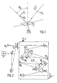
- a plane wave of polarization E ' p parallel to the plane of incidence and forming an angle ⁇ o with the normal to the surface of a sample ( Figure 1) is reflected in the form of a wave having a polarization E ⁇ p having undergone a rotation of ⁇ p relative to the incident wave.
- a plane wave of polarization E ⁇ s perpendicular to the plane of incidence is reflected in the form of a wave having a polarization E ⁇ s having undergone a rotation ⁇ s relative to the incident wave.
- ⁇ is a function of the angle of incidence as well as of the optical properties of the sample and therefore of the wavelength.
- ⁇ is a function of the optical properties of each layer and their thicknesses.
- ⁇ is also a function of the lateral coordinates of the sample.
- an ellipsometric measurement at a fixed wavelength does not allow a sufficiently fine analysis of the sample. It is therefore interesting to use another parameter, and in this case, it is the wavelength. It is therefore spectroscopic ellipsometry.
- Figure 2 depicts a prism monochromator with high spectral resolution and particularly suitable for the intended application. It includes as light source S a Xenon lamp of 900 W. Such a lamp has, in addition to good stability, an intense continuous background in a wide range going from infrared (a few microns) to ultraviolet (about 0, 22 micron).
- the input slot F of the monochromator is illuminated by an optical assembly of the KOHLER type.
- This arrangement provides uniform illumination. It has two spherical mirrors M1 and M2.
- the first mirror M1 projects the image of the arc of the source S on the mirror M2.
- the latter combines the mirror M1 on the input slot F of the monochromator.
- Two plane mirrors R1 and R2 allow to keep a low angle of incidence (about 5 °) on the spherical mirrors M1 and M2.
- a lens L, placed against the entry slit F makes it possible to project the image of the arc formed on the mirror M2 in the vicinity of infinity in the monochromator.
- the dispersive elements used are constituted by four double prisms in natural quartz PR1, PR2, PR ⁇ 2, PR ⁇ 1. This arrangement is equivalent to two simple monochromators (PR1, PR2) and (PR ⁇ 1, PR ⁇ 2) arranged symmetrically with respect to a central slot A.
- Concave mirrors, M3 upstream of the prism PR1 and M5 downstream of the prism PR2 for the first simple monochromator, and M ⁇ 5 upstream of the prism PR ⁇ 2 and M ⁇ 3 downstream of the prism PR ⁇ 1 for the second simple monochromator, constitute two so-called Z arrangements with equal angles of incidence.
- the assembly makes it possible to combine the inlet slot F, the central slot A and the outlet slot F ⁇ .
- the wavelength is selected using two plane mirrors respectively M respectivement arranged downstream of the prism PR aval and upstream of the prism PR2, and M ⁇ 4 disposed downstream of the prism PR ⁇ 2 and upstream of the prism PR ⁇ 1.
- a stepping motor 1 drives in simultaneous rotation the mirrors M en and M ⁇ 4 by means of a mechanical reduction.
- the stepping motor 1 is controlled by a computer according to a precise calibration law allowing linearization of the wavelength control.
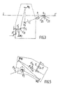
- FIG. 3 represents the optical illumination arm, the function of which, according to the invention, is to form on the surface of the sample a spot of small dimensions, for example of the order of 10 microns.
- the ellipsometer is of the spectroscopic type, a device is used using spherical mirrors. As the spherical mirrors are used in oblique incidence, they present an important astigmatism. The sagittal and tangential focal lengths are different. If one uses an optical assembly conjugating simply the exit slit F ⁇ of the monochromator and a point F ⁇ 2 of the surface of the sample, one obtains an image which is not in focus because of the astigmatism of the spherical mirrors.
- the correction of the effects due to astigmatism is carried out in accordance with FIG. 3.
- This uses two spherical mirrors M7 and M8, the mirror M7 having the function of forming two intermediate images F ⁇ 1T and F ⁇ 1S of the slit of F ⁇ output of the monochromator.
- the image F ⁇ 1S is taken up by the second adjustable mirror M8 which combines it into two images F ⁇ 2S F ⁇ 2T respectively upstream and downstream of F ⁇ 2 and in the close vicinity of F ⁇ 2 with the surface of the sample.
- a second slot is located in the plane of the image F ⁇ 1S and arranged perpendicular thereto.
- the fixed polarizer P is made of calcite and is integral with a calibration command constituted by a stepping motor and making it possible to orient the polarizer P before a measurement with an accuracy of one hundredth of a degree.
- the assembly also shows an electronic shutter C, located between the return mirror R4 and the polarizer P. This shutter C allows, when in the closed position, to determine the DC component, for example that due to the current detector darkness, to subtract it from the ellipsometric signal.
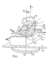
- the sample holder has two degrees of freedom of rotation around the axes ⁇ 1, ⁇ 2 and preferably a third degree of freedom around the axis ⁇ 3 and three degrees of freedom of translation along the axes T1 , T2 and T3.
- the first degree of freedom of rotation is obtained by two coaxial rotary movements.
- the first rotary movement around the axis ⁇ 1 which passes through the focal point F ⁇ 2 is ensured by a rotary plate PT1 controlled by a micrometric screw not shown.
- the PT1 plate is secured to a plate 10 which supports both the actual sample holder and the analysis arm which will be described later ( Figure 6).
- the rotation of the PT1 plate makes it possible to choose the angle of incidence in a manner which will be described later.
- a second rotating plate PT2 rotating around the axis ⁇ 1 which coincides with the axis ⁇ 1 in the adjustment position allows the sample to be oriented without changing the angle of incidence determined by the position of the first PT1 plate.
- the second rotation around a horizontal axis ⁇ 2 is obtained with a precision also of a hundredth of a degree by the displacement of a goniometric cradle 12 rotating in a support 11 mounted on the plate 10.
- the axis ⁇ 2 intersects the axis ⁇ 1 at the focal point F ⁇ 2.
- One of the consequences of this is that the axis ⁇ 1 always passes through the focal point F ⁇ 2.
- the goniometric cradle 11 carries the second PT2 plate which itself carries the rest of the apparatus ensuring the three translations along the axes T1, T2, T3 and the rotation around the axis ⁇ 3.
- the translation along the axis T2 parallel to the axis ⁇ 2 is ensured by a translation plate 20 mounted on the rotary plate PT2.
- the translation along the axis T3 perpendicular to the axis T2 and the axis ⁇ 1 is ensured by a translation plate 30 mounted on the translation plate 20.
- the translation along the axis T1 parallel to the axis ⁇ 1 is provided by a translation plate 40 mounted on the translation plate 30 via a bracket 41 and carrying a rotating plate 50 of axis ⁇ 3 parallel to the axis T3.
- the sample is fixed on the front face 51 of the turntable 50 whose rotation allows the sample to rotate on itself. This makes it possible to present, in a desired orientation, a sample having privileged directions (metallization lines, etc.).
- the translations T1 and T2 ensured by stepping motors with an increment of 0.1 micron make it possible to carry out a mapping of the sample, once the surface of the sample has been brought into coincidence with the focal point F ⁇ 2 by action on the translation T3.
- the action of the translations T1 and T2 does not undo the development.
- the fact that the axes ⁇ 1, ⁇ 2 pass through the focal point F ⁇ 2 has the consequence that the point of the surface of the sample coinciding with F inv remains invariant whatever the settings of the three rotations ⁇ 1, ⁇ 2 and ⁇ 3.
- the analysis arm secured to the movable plate that can pivot in its plane around the axis ⁇ 1 makes it possible to modify the angle of incidence but also to put the ellipsometer in configuration " straight line "in which there is no more reflection on the sample. This makes it possible to align the entire optical system as well as to take the reference for measuring the angle of incidence.
- the analysis arm comprises the sample holder as well as a detection system comprising a detection optic comprising two spherical mirrors M9 and M10, here of identical focal length, mounted in Z, a rotating analyzer, and a turret provided with different detectors , an alignment laser and an aiming microscope.
- the mirror M9 takes up the light beam reflected by the sample and returns it to the mirror M10 for focusing on the turret detectors after passage through the rotating analyzer A.
- the angle of incidence on the mirrors M9 and M10 was chosen as small as possible, in this case about 6 degrees, so as not to disturb the polarization of the reflected light.
- the rotary analyzer A is made of calcite and is mounted in the hollow shaft of a DC motor.
- An optical encoder is integral with the axis of the motor.
- the turret is movable in rotation around an axis YY ⁇ so as to allow placing on the optical path the different detectors which it carries, and covering different spectral ranges, as well as the alignment laser and the aiming microscope.
- the detectors are placed slightly behind the focal plane so as to ensure uniform illumination of each detector, with the possible exception of detectors whose sensitive surface is small and which can be placed in the focal plane.
- the aiming microscope at low magnification, allows the observation of the sample through the optical analysis system, as well as the adjustment of the position of the mirror M8 and of the slit F ⁇ 1S of the optical illumination arm.
- the alignment laser here a He-Ne laser, allows all the optical parts to be aligned, including the sample holder.
- the signal I supplied by the detector is sinusoidal, with a frequency twice that of the rotating analyzer. If we denote by A the angle of the rotating analyzer with respect to the p axis and by P the angle of the polarizer with respect to the p axis, we have: ⁇ 0 and ⁇ 0 being the normalized Fourier coefficients. From which it follows:
- the first operation consists in adjusting the position of the mirror M8 and of the slit F ⁇ 1S of the optical illumination arm using the aiming microscope.
- the laser beam located on the turret passes directly, without being reflected through the optical system in reverse path.
- the position of the analysis arm identified by the rotating plate PT platine for which the laser beam passes through the center of all the mirrors is taken as a reference for the measurement of the angle of incidence.
- the optical axis being thus materialized by the laser beam, the rotations are acted along the axes ⁇ 1 and ⁇ 2 of the sample holder so as to obtain perfect parallelism between the surface of the sample and the laser beam, that is ie the grazing incidence condition. Then acts on the translation along the axis T3 so as to close off half of the laser beam. This brings the focal point F ⁇ 2 of the lighting arm into coincidence with a point on the surface of the sample.
- the adjustment can be still improved after focusing.
- the analysis arm can be turned and put into measurement position.
- the rotation of the PT1 plate being measured with a precision to the hundredth of a degree, the angle of incidence is then determined with precision.
- Perfect orientation of the sample surface can preferably be obtained by studying the detected signal by putting the assembly in measurement configuration.
- the rotating analyzer is rotated with an angular frequency ⁇ .
- the detected signal is periodic with frequency 2 ⁇ .
- incorrect positioning of the sample with respect to the incidence plane causes periodic signals of frequency ⁇ to appear in the signal.
- the alignment of the sample is therefore carried out by acting on the rotations ⁇ 1 and ⁇ 2 so as to eliminate the parasitic component of frequency ⁇ .
- Visual examination of the signal on an oscilloscope by superimposing two periods of the signal of frequency 2 ⁇ makes it possible to easily highlight any component of frequency ⁇ .
- the remaining degrees of freedom no longer change the orientation of the sample plane. They make it possible to choose the point to be measured on the sample (translations T1 and T2) and to carry out maps of it, and in the case of a sample with patterns, to align these (rotation ⁇ 3) parallel to a given direction, for example the horizontal or vertical direction.
- the polarizer is manually set in the vicinity of the position p, ie at p0.
- the value of the residual and the phase of the signal are measured at 2N + 1 equidistant points in the interval p0- ⁇ p0, p0 + ⁇ p0.
- the variation of the residual around its minimum is approximated by a parabolic function whose coefficients are calculated by the method of least squares.
- This procedure makes it possible to position the polarizer with an accuracy of the order of those hundredths of a degree, and to determine all the parameters necessary to be able to deduce from the measured Fourier coefficients, the Fourier coefficients corrected for attenuation and phase shift .
Landscapes
- Physics & Mathematics (AREA)
- Health & Medical Sciences (AREA)
- Life Sciences & Earth Sciences (AREA)
- Chemical & Material Sciences (AREA)
- Analytical Chemistry (AREA)
- Biochemistry (AREA)
- General Health & Medical Sciences (AREA)
- General Physics & Mathematics (AREA)
- Immunology (AREA)
- Pathology (AREA)
- Investigating Or Analysing Materials By Optical Means (AREA)
- Length Measuring Devices By Optical Means (AREA)
Claims (5)
- Spektralellipsometer mit einer Beleuchtungseinrichtung, die einen Brennpunkt F'₂ zum Beleuchten einer Probenfläche der Probe (E) unter einem vorgegebenen Einfallswinkel besitzt, mit einer Einrichtung zum Analysieren des von der Probenfläche zurückgeworfenen Lichts sowie mit einem Probenträger zum deckungsgleichen Einstellen eines Punktes auf der Probenfläche mit dem Brennpunkt, dadurch gekennzeichnet, daß das Meter drei Translationsplatten, d.h. eine erste Platte (40) für eine erste Richtung (T₁), eine zweite Platte (20) für eine zweite Richtung (T₂) senkrecht zur ersten Richtung (T₁) und horizontal zur Verwirklichung kartographischer Probendaten sowie eine dritte Translationsplatte (30) für eine dritte Richtung (T₃) mit senkrechtem Verlauf zu den zwei anderen Richtungen und geeignet zum deckungsgleichen Anbringen eines Punktes der Probe mit dem Brennpunkt, und das Meter wenigstens zwei Drehplatten enthält, von denen die erste Platte (12) sich um eine erste Achse (ϑ₂) parallel zur zweiten horizontalen Richtung (T₂) und eine zweite Platte (PT2) sich um eine zweite Achse (ϑ'₁) parallel zur ersten Richtung (T₁) drehen, wobei diese beiden Achsen sich in einem mit dem Beleuchtungs-Brennpunkt zusammenfallenden Punkt derart schneiden, daß die Probe durch Drehung in zwei orthogonalen Ebenen um den Brennpunkt ausrichtbar ist.
- Ellipsometer nach Anspruch 1,
dadurch gekennzeichnet, daß der Probenträger auf einen Drehtisch (PT1) angebracht ist, dessen Vertikalachse (ϑ₁) durch den Brennpunkt F'₂ geht, und auf diesem Tisch die Analysiereinrichting derart montiert ist, daß der Einfallswinkel abänderbar ist. - Ellipsometer nach Anspruch 1 oder 2,
dadurch gekennzeichnet, daß der Probenträger eine dritte Drehplatte (50) zum Tragen der Probe enthält, und eine dritte Drehungsachse (ϑ₃) senkrecht zur ersten (ϑ₂) und zur zweiten Achse (ϑ'₁) besitzt, die eine Drehung der Probe in ihrer eigenen Ebene ermöglicht. - Ellipsometer nach einem der Ansprüche 1 bis 3, dadurch gekennzeichnet, daß die zweite Drehplatte (PT2) direkt auf der ersten Drehplatte (12) montiert ist, und daß die zweite (210) und die dritte Translationsplatte (30) in dieser Reihenfolge auf der zweiten Drehplatte (PT2) aufeinander gestellt sind, wobei die dritte Translationsplatte (30) die erste Translationsplatte (40) unterstützt, mit der die Probe verbunden ist.
- Ellipsometer nach den zusammengenommenen Ansprüchen 3 und 4, dadurch gekennzeichnet, daß die dritte Drehplatte (50) auf der ersten Translationsplatte (40) montiert ist.
Applications Claiming Priority (2)
| Application Number | Priority Date | Filing Date | Title |
|---|---|---|---|
| FR8614124A FR2605106B1 (fr) | 1986-10-10 | 1986-10-10 | Porte-echantillon pour un ellipsometre spectroscopique a haute resolution laterale |
| FR8614124 | 1986-10-10 |
Publications (2)
| Publication Number | Publication Date |
|---|---|
| EP0266814A1 EP0266814A1 (de) | 1988-05-11 |
| EP0266814B1 true EP0266814B1 (de) | 1991-06-12 |
Family
ID=9339749
Family Applications (1)
| Application Number | Title | Priority Date | Filing Date |
|---|---|---|---|
| EP87201919A Expired - Lifetime EP0266814B1 (de) | 1986-10-10 | 1987-10-07 | Probenträger für ein Spektralellipsometer mit hoher seitlicher Auflösung |
Country Status (5)
| Country | Link |
|---|---|
| US (1) | US4834539A (de) |
| EP (1) | EP0266814B1 (de) |
| JP (1) | JPH0692917B2 (de) |
| DE (1) | DE3770760D1 (de) |
| FR (1) | FR2605106B1 (de) |
Families Citing this family (16)
| Publication number | Priority date | Publication date | Assignee | Title |
|---|---|---|---|---|
| JPH0374348U (de) * | 1989-11-20 | 1991-07-25 | ||
| US5166752A (en) * | 1990-01-11 | 1992-11-24 | Rudolph Research Corporation | Simultaneous multiple angle/multiple wavelength ellipsometer and method |
| JP2574720Y2 (ja) * | 1990-10-15 | 1998-06-18 | 富士ゼロックス株式会社 | 傷検査用光学装置の位置調整装置 |
| US5129724A (en) * | 1991-01-29 | 1992-07-14 | Wyko Corporation | Apparatus and method for simultaneous measurement of film thickness and surface height variation for film-substrate sample |
| JPH06281567A (ja) * | 1992-02-29 | 1994-10-07 | New Oji Paper Co Ltd | 複屈折測定装置 |
| US5608526A (en) * | 1995-01-19 | 1997-03-04 | Tencor Instruments | Focused beam spectroscopic ellipsometry method and system |
| US6734967B1 (en) * | 1995-01-19 | 2004-05-11 | Kla-Tencor Technologies Corporation | Focused beam spectroscopic ellipsometry method and system |
| US5581350A (en) * | 1995-06-06 | 1996-12-03 | Tencor Instruments | Method and system for calibrating an ellipsometer |
| US5866900A (en) * | 1996-01-05 | 1999-02-02 | Raytheon Ti Systems, Inc. | Method and apparatus for calibrating a focal plane array of an image detector |
| JP4168543B2 (ja) * | 1998-10-08 | 2008-10-22 | 株式会社ニコン | 光学特性測定ユニット |
| US7230699B1 (en) * | 2002-10-15 | 2007-06-12 | J.A. Woollam Co., Inc. | Sample orientation system and method |
| US6642066B1 (en) | 2002-05-15 | 2003-11-04 | Advanced Micro Devices, Inc. | Integrated process for depositing layer of high-K dielectric with in-situ control of K value and thickness of high-K dielectric layer |
| US7978252B2 (en) * | 2005-03-30 | 2011-07-12 | Kyocera Corporation | Imaging apparatus, imaging system, and imaging method |
| US10240917B2 (en) * | 2015-01-23 | 2019-03-26 | Kyocera Corporation | Measuring apparatus and measuring method |
| US10444140B1 (en) * | 2019-03-18 | 2019-10-15 | J.A. Woollam Co., Inc. | Theta-theta sample positioning stage with application to sample mapping using reflectometer, spectrophotometer or ellipsometer system |
| CN110044613B (zh) * | 2019-04-18 | 2020-04-28 | 大连理工大学 | 基于轴盘的转子六自由度运动测试及其运动参数解耦方法 |
Family Cites Families (4)
| Publication number | Priority date | Publication date | Assignee | Title |
|---|---|---|---|---|
| US2947214A (en) * | 1958-06-02 | 1960-08-02 | Sylvania Electric Prod | Crystal orientation device |
| FR1575196A (de) * | 1967-08-05 | 1969-07-18 | ||
| US3564240A (en) * | 1969-07-22 | 1971-02-16 | Charles Supper Co Inc | Goniometer head for x-ray diffraction apparatus with improved z-motion mechanism |
| US4210401A (en) * | 1978-07-28 | 1980-07-01 | The United States Of America As Represented By The Administrator Of The National Aeronautics And Space Administration | Visible and infrared polarization ratio spectroreflectometer |
-
1986
- 1986-10-10 FR FR8614124A patent/FR2605106B1/fr not_active Expired
-
1987
- 1987-10-07 EP EP87201919A patent/EP0266814B1/de not_active Expired - Lifetime
- 1987-10-07 DE DE8787201919T patent/DE3770760D1/de not_active Expired - Lifetime
- 1987-10-12 JP JP62254829A patent/JPH0692917B2/ja not_active Expired - Lifetime
- 1987-10-14 US US07/108,404 patent/US4834539A/en not_active Expired - Fee Related
Also Published As
| Publication number | Publication date |
|---|---|
| EP0266814A1 (de) | 1988-05-11 |
| FR2605106B1 (fr) | 1988-12-09 |
| JPS63108236A (ja) | 1988-05-13 |
| FR2605106A1 (fr) | 1988-04-15 |
| DE3770760D1 (de) | 1991-07-18 |
| JPH0692917B2 (ja) | 1994-11-16 |
| US4834539A (en) | 1989-05-30 |
Similar Documents
| Publication | Publication Date | Title |
|---|---|---|
| EP0267634B1 (de) | Optische Vorrichtung zur Beleuchtung einer Probe in einem Spektralellipsometer mit hoher seitlicher Auflösung | |
| EP0266814B1 (de) | Probenträger für ein Spektralellipsometer mit hoher seitlicher Auflösung | |
| JP5368507B2 (ja) | 自己較正機能を備える表面特性解析用システム | |
| US6804003B1 (en) | System for analyzing surface characteristics with self-calibrating capability | |
| US6734968B1 (en) | System for analyzing surface characteristics with self-calibrating capability | |
| KR100917912B1 (ko) | 단일 편광자 초점 타원계측기 | |
| US5042951A (en) | High resolution ellipsometric apparatus | |
| CN102297721B (zh) | 斜入射宽带偏振光谱仪和光学测量系统 | |
| EP1060369A1 (de) | Verfahren zum messen der doppelbrechung | |
| US20100201981A1 (en) | Calibration method for optical metrology | |
| EP0332508B1 (de) | Apparat zur ellipsometrischen Untersuchung, Verfahren zur ellipsometrischen Untersuchung einer Probe, Verwendung zur Messung der Dickenänderung dünner Schichten | |
| EP0396409A2 (de) | Ellipsometrische Vorrichtung mit hohem Auflösungsvermögen | |
| CN100395538C (zh) | 一种新型快速椭圆偏振光测量系统 | |
| EP1640706A1 (de) | Wellenlängen- und Einfallswinkel-aufgelöstes Ellipsometer oder Reflektometer | |
| US20230324283A1 (en) | Spectroscopic ellipsometry system for thin film imaging | |
| US6618145B1 (en) | Spectroplarimetric reflectometer | |
| CN113358604A (zh) | 一种斜入射式光谱型反射差分测量装置及方法 | |
| Xia et al. | New design of the variable angle infrared spectroscopic ellipsometer using double Fourier transforms | |
| El-Agez et al. | Development and construction of rotating polarizer analyzer ellipsometer | |
| CN118129911A (zh) | 一种高保真偏振光谱系统 | |
| CN1207532C (zh) | 光学波片的检测仪 | |
| Matheson et al. | A high precision, polychromatic, automatic ellipsometer | |
| Dittmar et al. | Spectroscopic Ellipsometry in the Mid Infrared with a New Accessory Fitting into Standard Fourier-transform Spectrometers | |
| FR2501861A1 (fr) | Ellipsometre comportant un prisme a reflexions totales | |
| JPS63215923A (ja) | 分光測光装置における補助装置 |
Legal Events
| Date | Code | Title | Description |
|---|---|---|---|
| PUAI | Public reference made under article 153(3) epc to a published international application that has entered the european phase |
Free format text: ORIGINAL CODE: 0009012 |
|
| AK | Designated contracting states |
Kind code of ref document: A1 Designated state(s): DE FR GB IT NL |
|
| 17P | Request for examination filed |
Effective date: 19881021 |
|
| RAP1 | Party data changed (applicant data changed or rights of an application transferred) |
Owner name: N.V. PHILIPS' GLOEILAMPENFABRIEKEN Owner name: LABORATOIRES D'ELECTRONIQUE PHILIPS |
|
| 17Q | First examination report despatched |
Effective date: 19900117 |
|
| GRAA | (expected) grant |
Free format text: ORIGINAL CODE: 0009210 |
|
| AK | Designated contracting states |
Kind code of ref document: B1 Designated state(s): DE FR GB IT NL |
|
| REF | Corresponds to: |
Ref document number: 3770760 Country of ref document: DE Date of ref document: 19910718 |
|
| ITF | It: translation for a ep patent filed | ||
| GBT | Gb: translation of ep patent filed (gb section 77(6)(a)/1977) | ||
| PLBE | No opposition filed within time limit |
Free format text: ORIGINAL CODE: 0009261 |
|
| STAA | Information on the status of an ep patent application or granted ep patent |
Free format text: STATUS: NO OPPOSITION FILED WITHIN TIME LIMIT |
|
| 26N | No opposition filed | ||
| PGFP | Annual fee paid to national office [announced via postgrant information from national office to epo] |
Ref country code: GB Payment date: 19930929 Year of fee payment: 7 |
|
| PGFP | Annual fee paid to national office [announced via postgrant information from national office to epo] |
Ref country code: FR Payment date: 19931020 Year of fee payment: 7 |
|
| PGFP | Annual fee paid to national office [announced via postgrant information from national office to epo] |
Ref country code: NL Payment date: 19931031 Year of fee payment: 7 |
|
| PGFP | Annual fee paid to national office [announced via postgrant information from national office to epo] |
Ref country code: DE Payment date: 19931223 Year of fee payment: 7 |
|
| PG25 | Lapsed in a contracting state [announced via postgrant information from national office to epo] |
Ref country code: GB Effective date: 19941007 |
|
| PG25 | Lapsed in a contracting state [announced via postgrant information from national office to epo] |
Ref country code: NL Effective date: 19950501 |
|
| GBPC | Gb: european patent ceased through non-payment of renewal fee |
Effective date: 19941007 |
|
| NLV4 | Nl: lapsed or anulled due to non-payment of the annual fee | ||
| PG25 | Lapsed in a contracting state [announced via postgrant information from national office to epo] |
Ref country code: FR Effective date: 19950630 |
|
| PG25 | Lapsed in a contracting state [announced via postgrant information from national office to epo] |
Ref country code: DE Effective date: 19950701 |
|
| REG | Reference to a national code |
Ref country code: FR Ref legal event code: ST |
|
| PG25 | Lapsed in a contracting state [announced via postgrant information from national office to epo] |
Ref country code: IT Free format text: LAPSE BECAUSE OF NON-PAYMENT OF DUE FEES;WARNING: LAPSES OF ITALIAN PATENTS WITH EFFECTIVE DATE BEFORE 2007 MAY HAVE OCCURRED AT ANY TIME BEFORE 2007. THE CORRECT EFFECTIVE DATE MAY BE DIFFERENT FROM THE ONE RECORDED. Effective date: 20051007 |