EP0266832A1 - Vollständig digitaler Phasenregelkreis - Google Patents
Vollständig digitaler Phasenregelkreis Download PDFInfo
- Publication number
- EP0266832A1 EP0266832A1 EP87202058A EP87202058A EP0266832A1 EP 0266832 A1 EP0266832 A1 EP 0266832A1 EP 87202058 A EP87202058 A EP 87202058A EP 87202058 A EP87202058 A EP 87202058A EP 0266832 A1 EP0266832 A1 EP 0266832A1
- Authority
- EP
- European Patent Office
- Prior art keywords
- phase
- locked loop
- digital
- signal
- sampling
- Prior art date
- Legal status (The legal status is an assumption and is not a legal conclusion. Google has not performed a legal analysis and makes no representation as to the accuracy of the status listed.)
- Granted
Links
- 238000005070 sampling Methods 0.000 claims abstract description 33
- 238000012937 correction Methods 0.000 claims description 37
- 230000005540 biological transmission Effects 0.000 claims description 7
- 238000001914 filtration Methods 0.000 claims description 4
- 238000010586 diagram Methods 0.000 description 8
- 238000013459 approach Methods 0.000 description 5
- 238000004458 analytical method Methods 0.000 description 4
- 238000000034 method Methods 0.000 description 4
- 238000012545 processing Methods 0.000 description 4
- 238000012544 monitoring process Methods 0.000 description 3
- 230000010355 oscillation Effects 0.000 description 3
- 238000004088 simulation Methods 0.000 description 3
- 238000004364 calculation method Methods 0.000 description 2
- 230000003111 delayed effect Effects 0.000 description 2
- 229940082150 encore Drugs 0.000 description 2
- 238000012986 modification Methods 0.000 description 2
- 230000004048 modification Effects 0.000 description 2
- 240000008042 Zea mays Species 0.000 description 1
- 230000015572 biosynthetic process Effects 0.000 description 1
- 238000006243 chemical reaction Methods 0.000 description 1
- 238000004891 communication Methods 0.000 description 1
- 239000000470 constituent Substances 0.000 description 1
- 238000001514 detection method Methods 0.000 description 1
- 230000008030 elimination Effects 0.000 description 1
- 238000003379 elimination reaction Methods 0.000 description 1
- 238000011156 evaluation Methods 0.000 description 1
- 230000000737 periodic effect Effects 0.000 description 1
- 230000010363 phase shift Effects 0.000 description 1
- 238000011002 quantification Methods 0.000 description 1
- 238000013139 quantization Methods 0.000 description 1
- 230000003068 static effect Effects 0.000 description 1
- 230000001629 suppression Effects 0.000 description 1
- 238000003786 synthesis reaction Methods 0.000 description 1
Images


Classifications
-
- H—ELECTRICITY
- H03—ELECTRONIC CIRCUITRY
- H03L—AUTOMATIC CONTROL, STARTING, SYNCHRONISATION OR STABILISATION OF GENERATORS OF ELECTRONIC OSCILLATIONS OR PULSES
- H03L7/00—Automatic control of frequency or phase; Synchronisation
- H03L7/06—Automatic control of frequency or phase; Synchronisation using a reference signal applied to a frequency- or phase-locked loop
- H03L7/08—Details of the phase-locked loop
- H03L7/099—Details of the phase-locked loop concerning mainly the controlled oscillator of the loop
- H03L7/0991—Details of the phase-locked loop concerning mainly the controlled oscillator of the loop the oscillator being a digital oscillator, e.g. composed of a fixed oscillator followed by a variable frequency divider
Definitions
- the invention relates to a fully digital phase locked loop produced using a digital signal processor and comprising a sampler-blocker followed by an analog-digital converter and a filter assembly connected to the input. a decision logic whose output controls said sampler-blocker.
- Phase locked loops are used in the widest fields of telecommunications (radiolocation) as well as in metrology (frequency synthesis). The main property of these loops is to allow synchronization on a signal during noisy transmissions when the conventional detection means are inoperative in the face of the weak signal received.
- a digital phase locked loop as mentioned in the preamble is described in the article entitled “Digital Phase-Locked Loop Behavior with Clock and Sampler Quantization” by Carlos POLAMAZA-RAEZ and Clare D.McGtLLEM published in IEEE Transactions on Communications, voI.COM-33, N ° 8, August 1985, pages 753 to 759.
- the loop of the invention was implemented in a cryptophony equipment to ensure at reception the synchronization of the sampling of the scrambled digital speech signal.
- cryptographic equipment carrying out the interference by permutation of frequency sub-bands using digital processing. it is essential to find the exact synchronization of the samples on reception.
- the aim is to obtain an accelerated synchronization by using a double locking speed allowing a rapid approach at the start of convergence then a slower and more precise approach for the end of convergence and monitoring.
- phase-locked loop of the invention will be presented to the sampling synchronization of a scrambled digital signal by permutation of frequency sub-bands. After transmission, said signal is not directly usable as shown in the following analysis of its sampling phase.
- x b (n) be the digital scrambled signal transmitted and x b '(n) the digital scrambled signal after transmission by the analog channel.
- the value of D is not indifferent: indeed, after analysis of the signal x, the sub-band signals xc, x 1 , ..., x N-1 corresponding respectively to the sub -bands 0, 1, ..., N-1 must check: where me is an integer value, that is to say that we must find the sub-band signals as they were calculated with a delay.
- the signal z coming from the demodulator 4 is subtracted at 8 from the received signal in order to compensate for the elimination of the synchronization carrier.
- the sampling phase correction is carried out around the free frequency value (fe) by adding or removing a certain number of "machine" cycles from said processor.
- variable voltage of a VCO in an analog phase locked loop was thus replaced by a variation of "machine" cycles in the digital phase locked loop.
- fo fe / 4 as the frequency of the synchronization wave. This choice is not limiting and the processing performed when the frequency of the synchronization wave is f e / p will be explained below. p being an integer greater than 2.
- a signal for which f o , f e / 4 can be represented in digital form subsequently + A, 0, -A, 0, + A, 0, ... where A represents the peak amplitude of the wave synchronization.
- A represents the peak amplitude of the wave synchronization.
- At the reception can be represented subsequently 0, + 1 , 0, -1, 0. + 1 .... after sampling at f e and can be represented hereinafter + ⁇ , 0, - ⁇ , 0, + 1, 0, .... which particularly simplifies the demodulation operations.
- FIG. 4a the evolution of the sampling phase error ⁇ during the acquisition is plotted, as a function of n, the sample considered.
- Figure 4c shows the evolution of the quantities
- and the az threshold ( ⁇ 1 4). The intersection of the two curves corresponds to the switching instant between fast approach and slow approach.
- phase error m is -135 °; a rapid convergence process begins, materialized by the linear part of Figure 4a.
- a second process begins, materialized in FIGS. 4a and 4b by oscillations around 0, caused by strong corrections affected by the sign of u (n).
- the phase ⁇ remaining however around 0.
- y (n) which corresponds to an energetic filtering of Asin ⁇ will approach zero, and a third process begins when we reach
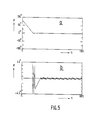
- Figures 5a and 5b show a convergence in the case of an offset (5.10- 5 in relative value) of free frequency between wave synchronization and sampling.
- the larger phase oscillations around zero are produced by the need to permanently correct the local frequency.
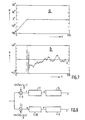
- FIGS. 6a and 6b show the behavior of the loop in the presence of noise but without shifting the free frequencies, the signal to noise ratio being 28 dB. Thanks to the energetic filtering carried out by filters 5 and 6, the noise has very little influence on the sampling phase after convergence.
- Figures 7a and 7b show a convergence in the presence of noise and an offset free frequencies (signal to noise ratio: 28 dB, frequency offset: 5.10- 5 in relative value).
- the behavior of the loop is still acceptable with 20 dB signal to noise ratio and 10- 4 drift.
- the synchronization wave residue is weakened by at least 22 dB compared to the initial wave, which allows a frequency to be chosen located in the bandwidth of the channel (example: fe / 4. fe / 3, etc.).
- the locking loop operates in a completely analogous manner when the synchronization frequency is equal, no longer at f e / 4, but at f e / p (p> 2, p * 4).
- the sampled synchronization wave can be represented by Demodulators 3 and 4 use the signals respectively: and The sequences of the output states of 3 and 4 are respectively: u (n): Asin ⁇ ; -1/2 Asin ( ⁇ + 2 ⁇ / 3), -1/2 Asin ( ⁇ + 4 ⁇ / 3), ... v (n): 0, ⁇ 3 / 2 Asin ( ⁇ + 2 ⁇ / 3 ). -V3 / 2 Asin ( ⁇ + 4 ⁇ / 3), ...
- the filters calculate respectively:
Landscapes
- Synchronisation In Digital Transmission Systems (AREA)
- Stabilization Of Oscillater, Synchronisation, Frequency Synthesizers (AREA)
- Digital Transmission Methods That Use Modulated Carrier Waves (AREA)
Applications Claiming Priority (2)
| Application Number | Priority Date | Filing Date | Title |
|---|---|---|---|
| FR8615210A FR2606238B1 (fr) | 1986-10-31 | 1986-10-31 | Boucle a verrouillage de phase entierement numerique |
| FR8615210 | 1986-10-31 |
Publications (2)
| Publication Number | Publication Date |
|---|---|
| EP0266832A1 true EP0266832A1 (de) | 1988-05-11 |
| EP0266832B1 EP0266832B1 (de) | 1992-01-15 |
Family
ID=9340416
Family Applications (1)
| Application Number | Title | Priority Date | Filing Date |
|---|---|---|---|
| EP87202058A Expired - Lifetime EP0266832B1 (de) | 1986-10-31 | 1987-10-27 | Vollständig digitaler Phasenregelkreis |
Country Status (5)
| Country | Link |
|---|---|
| US (1) | US4969191A (de) |
| EP (1) | EP0266832B1 (de) |
| JP (1) | JPS63164531A (de) |
| DE (1) | DE3776082D1 (de) |
| FR (1) | FR2606238B1 (de) |
Cited By (1)
| Publication number | Priority date | Publication date | Assignee | Title |
|---|---|---|---|---|
| RU2599347C1 (ru) * | 2015-03-27 | 2016-10-10 | Федеральное государственное казенное военное образовательное учреждение высшего профессионального образования "Военный учебно-научный центр Военно-воздушных сил "Военно-воздушная академия имени профессора Н.Е. Жуковского и Ю.А. Гагарина" (г. Воронеж) Министерства обороны Российской Федерации | Способ усиления и демодуляции частотно-модулированных сигналов и устройство его реализации |
Families Citing this family (2)
| Publication number | Priority date | Publication date | Assignee | Title |
|---|---|---|---|---|
| JP3113667B2 (ja) * | 1990-05-30 | 2000-12-04 | 日本テキサス・インスツルメンツ株式会社 | トランスバーサルフィルタ回路 |
| JP3241079B2 (ja) * | 1992-02-24 | 2001-12-25 | 株式会社日立製作所 | ディジタル位相同期回路 |
Citations (4)
| Publication number | Priority date | Publication date | Assignee | Title |
|---|---|---|---|---|
| US3777272A (en) * | 1972-09-18 | 1973-12-04 | Nasa | Digital second-order phase-locked loop |
| EP0035166A1 (de) * | 1980-03-01 | 1981-09-09 | Licentia Patent-Verwaltungs-GmbH | Digitaler Empfänger |
| US4457003A (en) * | 1982-06-21 | 1984-06-26 | Motorola Inc. | Time reference tracking loop for frequency hopping systems |
| US4594555A (en) * | 1984-10-29 | 1986-06-10 | Hewlett-Packard Company | Frequency selective sampling detector |
Family Cites Families (13)
| Publication number | Priority date | Publication date | Assignee | Title |
|---|---|---|---|---|
| US4004237A (en) * | 1970-05-01 | 1977-01-18 | Harris Corporation | System for communication and navigation |
| US3971996A (en) * | 1973-01-18 | 1976-07-27 | Hycom Incorporated | Phase tracking network |
| US4028626A (en) * | 1973-01-18 | 1977-06-07 | Hycom Incorporated | Digital data receiver with automatic timing recovery and control |
| NL171215C (nl) * | 1973-03-09 | 1983-02-16 | Trt Telecom Radio Electr | Automatische egalisatie-inrichting voor een datatransmissiekanaal. |
| JPS5152264A (de) * | 1974-09-11 | 1976-05-08 | Sharp Kk | |
| US3962637A (en) * | 1974-11-11 | 1976-06-08 | Hycom Incorporated | Ultrafast adaptive digital modem |
| US3978407A (en) * | 1975-07-23 | 1976-08-31 | Codex Corporation | Fast start-up adaptive equalizer communication system using two data transmission rates |
| US4004226A (en) * | 1975-07-23 | 1977-01-18 | Codex Corporation | QAM receiver having automatic adaptive equalizer |
| FR2445079A1 (fr) * | 1978-12-20 | 1980-07-18 | Ibm France | Procede et dispositif pour detecter une sequence pseudo-aleatoire de changements de phase de 0o et 180o de la porteuse dans un recepteur de donnees |
| FR2445078A1 (fr) * | 1978-12-20 | 1980-07-18 | Ibm France | Procede et dispositif pour detecter une sequence pseudo-aleatoire de deux symboles dans un recepteur de donnees utilisant une modulation a double bande laterale-porteuses en quadrature |
| US4237554A (en) * | 1979-03-01 | 1980-12-02 | Bell Telephone Laboratories, Incorporated | Coefficient tap leakage for fractionally-spaced equalizers |
| US4680621A (en) * | 1985-09-16 | 1987-07-14 | Tektronix, Inc. | Method and apparatus for variable phasing of periodic signals |
| JPS63252014A (ja) * | 1987-04-08 | 1988-10-19 | Kokusai Denshin Denwa Co Ltd <Kdd> | 位相同期方式 |
-
1986
- 1986-10-31 FR FR8615210A patent/FR2606238B1/fr not_active Expired
-
1987
- 1987-10-27 EP EP87202058A patent/EP0266832B1/de not_active Expired - Lifetime
- 1987-10-27 DE DE8787202058T patent/DE3776082D1/de not_active Expired - Fee Related
- 1987-10-29 JP JP62271954A patent/JPS63164531A/ja active Pending
- 1987-10-30 US US07/115,475 patent/US4969191A/en not_active Expired - Fee Related
Patent Citations (4)
| Publication number | Priority date | Publication date | Assignee | Title |
|---|---|---|---|---|
| US3777272A (en) * | 1972-09-18 | 1973-12-04 | Nasa | Digital second-order phase-locked loop |
| EP0035166A1 (de) * | 1980-03-01 | 1981-09-09 | Licentia Patent-Verwaltungs-GmbH | Digitaler Empfänger |
| US4457003A (en) * | 1982-06-21 | 1984-06-26 | Motorola Inc. | Time reference tracking loop for frequency hopping systems |
| US4594555A (en) * | 1984-10-29 | 1986-06-10 | Hewlett-Packard Company | Frequency selective sampling detector |
Non-Patent Citations (1)
| Title |
|---|
| IEEE TRANSACTIONS ON INDUSTRIAL ELECTRONICS AND CONTROL INSTRUMENTATION, vol. IECI-20, no. 4, novembre 1973, pages 239-251, New York, US; C.P. REDDY et al.: "A class of all digital phase locked loops: Modeling and analysis" * |
Cited By (1)
| Publication number | Priority date | Publication date | Assignee | Title |
|---|---|---|---|---|
| RU2599347C1 (ru) * | 2015-03-27 | 2016-10-10 | Федеральное государственное казенное военное образовательное учреждение высшего профессионального образования "Военный учебно-научный центр Военно-воздушных сил "Военно-воздушная академия имени профессора Н.Е. Жуковского и Ю.А. Гагарина" (г. Воронеж) Министерства обороны Российской Федерации | Способ усиления и демодуляции частотно-модулированных сигналов и устройство его реализации |
Also Published As
| Publication number | Publication date |
|---|---|
| US4969191A (en) | 1990-11-06 |
| EP0266832B1 (de) | 1992-01-15 |
| JPS63164531A (ja) | 1988-07-07 |
| FR2606238A1 (fr) | 1988-05-06 |
| FR2606238B1 (fr) | 1988-12-09 |
| DE3776082D1 (de) | 1992-02-27 |
Similar Documents
| Publication | Publication Date | Title |
|---|---|---|
| EP0054829B1 (de) | Verfahren und Einrichtung zur Detektion der Trainingsfolge eines autoadaptiven Entzerrers | |
| EP0036084A1 (de) | Verfahren und Vorrichtung zum Steuern der Beginneinstellung des Taktgebers eines Empfängers für synchrone Daten | |
| FR2568014A1 (fr) | Dispositif de detection de parasites en forme d'impulsion et dispositif de suppression de parasites en forme d'impulsion muni d'un dispositif de detection de parasites en forme d'impulsion | |
| EP0223657A1 (de) | Rechnungseinrichtung von diskreter Fouriertransformation und seine Anwendung auf einem Radarsystem | |
| EP0012884B1 (de) | Verfahren und Vorrichtung zur Auffindung einer Pseudo-Zufallsfolge zweier Symbole in einem Datenempfänger, welcher eine Doppelzeitenbandmodulation mit Quadraturträgern verwendet | |
| EP1782536B1 (de) | Verfahren zum erzeugen eines digitalsignals, das anpassungsfehler in einem analog/digital-umsetzungssystem mit zeitverschachtelung repräsentiert und analog/digital-umsetzer mit zeitverschachtelung damit | |
| EP0266832B1 (de) | Vollständig digitaler Phasenregelkreis | |
| EP0209928B1 (de) | Demodulator für frequenzmodulierte digitale Signale | |
| EP0205150A1 (de) | Verfahren und Anordnung für Verringerung des Phasenzitterns einer synchronen digitalen Impulsfolge zur Taktwiedergewinnung | |
| EP0230900B1 (de) | Taktwiedergewinnungseinrichtung | |
| FR2519818A1 (fr) | Boucle a blocage de phase et procede pour en ameliorer le signal de sortie | |
| Poberezhskiy et al. | Sampling technique allowing exclusion of antialiasing filter | |
| EP0035295A1 (de) | Verfahren zur Regelung der Phase des Taktgenerators eines Empfangssystems für digitale Daten, Phasenrückgewinnungsschaltung zur Durchführung dieses Verfahrens und Empfangssystem für digitale Daten mit dieser Schaltung | |
| WO1995022196A1 (fr) | Dispositif de modulation de phase continue par synthetiseur de frequences a boucle a verrouillage de phase | |
| EP1940023A2 (de) | Kaskadierbare, digitale Filterbank und darin enthaltene Empfangsschaltung | |
| EP0205373A1 (de) | Digitaler einstellbarer Phasenschieber und digitaler Laufzeitentzerrer für Magnetbildaufzeichnungsanlage mit solch einem Phasenschieber | |
| EP0218508B1 (de) | Schnell variierbarer Frequenzgenerator | |
| EP0181808B1 (de) | Spektralanalysator unter verwendung von Oberflächenwellendispersionsfiltern | |
| EP0461022B1 (de) | Einrichtung zur Trägerrückgewinnung mit Mittel zum Verhindern falscher Frequenzverriegelung | |
| EP0737868B1 (de) | Verzögerungsregelschleife für GPS Empfänger | |
| FR2908946A1 (fr) | Bvp numerique fractionnaire | |
| EP3021139B1 (de) | Signalerfassung und Entfernungsabweichungsmesssystem für Laser-Entfernungsmessinterferometer | |
| FR2587498A1 (fr) | Detecteur de phase et, ou bien, frequence numerique sur un large intervalle | |
| FR2485296A1 (fr) | Circuit numerique analyseur de frequence programmable | |
| EP0031270B1 (de) | Filtervorrichtung mit geringer Phasenverzerrung und Schaltung zur Behandlung von Farbfernsehsignalen mit einer solchen Vorrichtung |
Legal Events
| Date | Code | Title | Description |
|---|---|---|---|
| PUAI | Public reference made under article 153(3) epc to a published international application that has entered the european phase |
Free format text: ORIGINAL CODE: 0009012 |
|
| AK | Designated contracting states |
Kind code of ref document: A1 Designated state(s): DE FR GB IT SE |
|
| 17P | Request for examination filed |
Effective date: 19881021 |
|
| 17Q | First examination report despatched |
Effective date: 19910125 |
|
| RAP1 | Party data changed (applicant data changed or rights of an application transferred) |
Owner name: THOMSON-TRT DEFENSE |
|
| RAP1 | Party data changed (applicant data changed or rights of an application transferred) |
Owner name: THOMSON-TRT DEFENSE |
|
| GRAA | (expected) grant |
Free format text: ORIGINAL CODE: 0009210 |
|
| AK | Designated contracting states |
Kind code of ref document: B1 Designated state(s): DE FR GB IT SE |
|
| ITF | It: translation for a ep patent filed | ||
| RAP2 | Party data changed (patent owner data changed or rights of a patent transferred) |
Owner name: THOMSON-TRT DEFENSE |
|
| REF | Corresponds to: |
Ref document number: 3776082 Country of ref document: DE Date of ref document: 19920227 |
|
| GBT | Gb: translation of ep patent filed (gb section 77(6)(a)/1977) | ||
| PG25 | Lapsed in a contracting state [announced via postgrant information from national office to epo] |
Ref country code: GB Effective date: 19921027 |
|
| PG25 | Lapsed in a contracting state [announced via postgrant information from national office to epo] |
Ref country code: SE Effective date: 19921028 |
|
| PLBE | No opposition filed within time limit |
Free format text: ORIGINAL CODE: 0009261 |
|
| STAA | Information on the status of an ep patent application or granted ep patent |
Free format text: STATUS: NO OPPOSITION FILED WITHIN TIME LIMIT |
|
| 26N | No opposition filed | ||
| GBPC | Gb: european patent ceased through non-payment of renewal fee |
Effective date: 19921027 |
|
| PG25 | Lapsed in a contracting state [announced via postgrant information from national office to epo] |
Ref country code: FR Effective date: 19930630 |
|
| PG25 | Lapsed in a contracting state [announced via postgrant information from national office to epo] |
Ref country code: DE Effective date: 19930701 |
|
| REG | Reference to a national code |
Ref country code: FR Ref legal event code: ST |
|
| EUG | Se: european patent has lapsed |
Ref document number: 87202058.1 Effective date: 19930510 |
|
| PG25 | Lapsed in a contracting state [announced via postgrant information from national office to epo] |
Ref country code: IT Free format text: LAPSE BECAUSE OF NON-PAYMENT OF DUE FEES;WARNING: LAPSES OF ITALIAN PATENTS WITH EFFECTIVE DATE BEFORE 2007 MAY HAVE OCCURRED AT ANY TIME BEFORE 2007. THE CORRECT EFFECTIVE DATE MAY BE DIFFERENT FROM THE ONE RECORDED. Effective date: 20051027 |