EP0266841A1 - Appareil d'enregistrement de données optiques - Google Patents
Appareil d'enregistrement de données optiques Download PDFInfo
- Publication number
- EP0266841A1 EP0266841A1 EP87202112A EP87202112A EP0266841A1 EP 0266841 A1 EP0266841 A1 EP 0266841A1 EP 87202112 A EP87202112 A EP 87202112A EP 87202112 A EP87202112 A EP 87202112A EP 0266841 A1 EP0266841 A1 EP 0266841A1
- Authority
- EP
- European Patent Office
- Prior art keywords
- light
- recording medium
- grating
- laser
- light source
- Prior art date
- Legal status (The legal status is an assumption and is not a legal conclusion. Google has not performed a legal analysis and makes no representation as to the accuracy of the status listed.)
- Granted
Links
- 230000003287 optical effect Effects 0.000 title claims abstract description 14
- 230000010287 polarization Effects 0.000 abstract description 7
- 201000009310 astigmatism Diseases 0.000 abstract description 2
- 239000000758 substrate Substances 0.000 description 4
- 230000005540 biological transmission Effects 0.000 description 3
- 238000010348 incorporation Methods 0.000 description 2
- 108010010803 Gelatin Proteins 0.000 description 1
- 238000010276 construction Methods 0.000 description 1
- 229920000159 gelatin Polymers 0.000 description 1
- 239000008273 gelatin Substances 0.000 description 1
- 235000019322 gelatine Nutrition 0.000 description 1
- 235000011852 gelatine desserts Nutrition 0.000 description 1
- 239000011521 glass Substances 0.000 description 1
- 230000002452 interceptive effect Effects 0.000 description 1
- 238000000034 method Methods 0.000 description 1
- 229920000642 polymer Polymers 0.000 description 1
- 239000004065 semiconductor Substances 0.000 description 1
Images


Classifications
-
- G—PHYSICS
- G11—INFORMATION STORAGE
- G11B—INFORMATION STORAGE BASED ON RELATIVE MOVEMENT BETWEEN RECORD CARRIER AND TRANSDUCER
- G11B7/00—Recording or reproducing by optical means, e.g. recording using a thermal beam of optical radiation by modifying optical properties or the physical structure, reproducing using an optical beam at lower power by sensing optical properties; Record carriers therefor
- G11B7/12—Heads, e.g. forming of the optical beam spot or modulation of the optical beam
- G11B7/135—Means for guiding the beam from the source to the record carrier or from the record carrier to the detector
- G11B7/1353—Diffractive elements, e.g. holograms or gratings
Definitions
- This invention relates to optical data recording device comprising: a laser light source for producing a recording beam; focussing means disposed between the light source and a recording medium for focusing the recording beam on the recording medium; a polarisation-rotating means arranged between the light source and the recording medium, and a light detector for receiving the returned reflected light from the recording medium.
- a polarized beam splitter is used as an optical switch.
- the splitter passes all of the light from a laser light source to a recording medium, and at the same time it isolates the reflected beam from the medium to prevent the light from returning to the laser.
- This phenomenon is based on the principle that a specially coated beam splitter can reflect most of the light which is polarized perpendicular to its plane of incidence and transmit all the light polarized in its plane of incidence.
- the use of polarized beam splitters with quarter wave retardation plates is expensive.
- the optical data recording device of the present invention is characterized in that between the light source and the polarisation rotating means a holographic grating is disposed for directing light towards the detector.
- the invention uses an inexpensive holographic grating as a polarization beam splitter. Further, the holographic grating has the inherent features of creating a circular beam shape from a typical elliptical beam shape transmitted from the laser light source. This greatly reduces the spot size sof the focused beam on the recording medium.
- a prior art optical storage device 10 is represented having a collimated beam of light indicated by arrows 12 produced from a laser 14.
- the light 12 is linearly polarized in the plane of incidence of a beam splitter 16.
- the light 12 is fully transmitted in this example by the beam splitter 16.
- the polarization of the light 12 is such that the beam splitter 16 transmits all of its power.
- the light then passes through a quarter wave retardation plate 18 and through an objective lens 20 where it is focused onto a recording medium such as a rotating optical disk 22.
- the return light is polarized at 90 degrees from the original polarization of the laser 14. Accordingly, it is reflected by the beam splitter 16 through a toric lens 24 onto a light detector 26. Little of the return light is transmitted back to the laser source 14.
- Fig. 1A depicts a typical light detector having quad like zones 1, 2, 3 and 4.
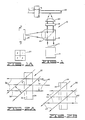
- Fig. 2A illustrates the general principle of making a high efficiency holographic grating having general reference numeral 30.
- the grating 30 includes a light sensitive layer 32 and substrate 34.
- the layer 32 and substrate 34 making up the holographic grating 30 are greatly enlarged in this drawing for illustration only.
- Two collimated beams of light 36 and 38 interfere onto the light sensitive layer 32 which is supported by the substrate 34. Both beams are polarized perpendicular to the plane of incidence of the holographic grating 30.
- the holographic grating 30 made in this configuration is a transmission holographic grating which means that upon illuminating the hologram grating by a reconstruction beam similar to the beam 36 a beam 40 appears as a continuation of the beam 38.
- the light sensitive layer 32 can be a photosensitive polymer or dichromated gelatin. The thickness of the layer 32 must be many times the wave length of the light used with the recording device 10.
- the width of the beam 36 is L1 and the beam width of the constructed beam 40 is L2.
- the width L2 of the reconstructed beam is equal to 2L1.
- the incident beam is expanded along one direction by a factor of 2.
- Fig. 2B is an illustration of a reflection hologram grating 30 similar to that described for Fig. 2A, comprising a light-sensitive layer 32 on a substrate 34.
- the hollogram is formed by two collimated beams of light 42 and 44 now coming from opposite directions and interfering on the light-sensitive layer 32.
- a beam 46 is reflected from the hologram grating 30.
- Figs. 3 and 3B shown an embodiment of the present invention having a general reference numeral 50 in which the transmission hologram grating 30 is used.
- the hologram grating 30 is constructed in such a way that a collimated beam 52 with elliptical cross-section (in dash lines and also shown in Fig. 3B) from a laser 54 will become a beam 56 with a circular cross-section (in dash lines and also shown in Fig. 3C) after passage through the hoologram grating.
- the beam 56 from the laser 54 and the grating 30 are rotated 45 degrees so that the polarization of the beam 56 is at 45 degrees with respect to the plane of incidence on a prism 58 which reflects the beam towards an objective lens 59.
- coated mirrors or prisms can cause phase retardation on the incident beam. Because of the prism 58, the polarization of the return beam from a recording medium 60 and from the prism 58 is rotated by 90 degrees from that of the original beam 56. As a result, most of the reflected beam is transmitted through the hologram grating 30 and focused by a toric lens 62 onto a light detector 64.
- the detector 64 is shown in Fig. 3A with four quad zones 1, 2, 3 and 4.
- Fig. 4 illustrates another embodiment of the subject invention in which a reflection hologram grating 30 is used.
- the advantage of this embodiment is that the toric lens 62 is bonded to one side of the grating 30 to eliminate the need of a support for the toric lens 62.
- Fig. 4A again shows zones 1, 2, 3 and 4 of the detector 64.
- Figs. 5A and 5B show the incorporation of a wave front from a cylindrical lens onto th e hologram grating 30.
- the cylindrical wave front of a light beam 66 is produced by a negative cylindrical lens 70 on a positive cylindrical lens 68.
- the cylindircal wave front is used to compensate for astigmatism in many of the semiconductor laser diodes.
- the so-called astigmatic distance in laser diodes ranges from one micrometer to about 25 micrometers. It is difficult and costly to polish a glass cylindrical lens to correct this type of abberation.
- the hologram grating 30 the light source wave front can be easily and inexpensively corrected.
Landscapes
- Physics & Mathematics (AREA)
- Optics & Photonics (AREA)
- Optical Head (AREA)
Applications Claiming Priority (2)
| Application Number | Priority Date | Filing Date | Title |
|---|---|---|---|
| US927924 | 1986-11-06 | ||
| US06/927,924 US4789977A (en) | 1986-11-06 | 1986-11-06 | Optical data recording device |
Publications (2)
| Publication Number | Publication Date |
|---|---|
| EP0266841A1 true EP0266841A1 (fr) | 1988-05-11 |
| EP0266841B1 EP0266841B1 (fr) | 1992-02-19 |
Family
ID=25455463
Family Applications (1)
| Application Number | Title | Priority Date | Filing Date |
|---|---|---|---|
| EP87202112A Expired EP0266841B1 (fr) | 1986-11-06 | 1987-11-04 | Appareil d'enregistrement de données optiques |
Country Status (4)
| Country | Link |
|---|---|
| US (1) | US4789977A (fr) |
| EP (1) | EP0266841B1 (fr) |
| JP (1) | JPS63171439A (fr) |
| DE (1) | DE3776755D1 (fr) |
Cited By (4)
| Publication number | Priority date | Publication date | Assignee | Title |
|---|---|---|---|---|
| EP0453323A3 (en) * | 1990-04-20 | 1992-06-03 | Sharp Kabushiki Kaisha | Optical pickup device |
| EP0559435A1 (fr) * | 1992-03-05 | 1993-09-08 | International Business Machines Corporation | Améliorations dans les techniques holographiques |
| EP0539217A3 (en) * | 1991-10-25 | 1993-09-29 | Tandy Corporation | Holographic elements for an optical recording system |
| EP0715200A3 (fr) * | 1994-12-02 | 1997-12-10 | Xerox Corporation | Elément optique pour la correction du tremblement et la mise au point, présentant une surface toroidale et une surface optique diffractante binaire |
Families Citing this family (22)
| Publication number | Priority date | Publication date | Assignee | Title |
|---|---|---|---|---|
| US4905216A (en) * | 1986-12-04 | 1990-02-27 | Pencom International Corporation | Method for constructing an optical head by varying a hologram pattern |
| EP0311340B1 (fr) * | 1987-10-05 | 1993-08-04 | Matsushita Electric Industrial Co., Ltd. | Tête de lecture optique |
| EP0348221B1 (fr) * | 1988-06-23 | 1994-12-14 | Sharp Kabushiki Kaisha | Appareil de reproduction optique |
| US4993789A (en) * | 1988-09-15 | 1991-02-19 | Jonathan R. Biles | Dual wavelength polarization selective holographic optical element |
| US5044709A (en) * | 1988-11-30 | 1991-09-03 | Hughes Aircraft Company | LED array polarized image source/0 degree hologram virtual image head up display |
| JPH06103543B2 (ja) * | 1988-12-31 | 1994-12-14 | 三星電子株式会社 | レーザピックアップ |
| US5009502A (en) * | 1989-04-20 | 1991-04-23 | Hughes Aircraft Company | System of holographic optical elements for testing laser range finders |
| JPH0460933A (ja) * | 1990-06-26 | 1992-02-26 | Matsushita Electric Ind Co Ltd | 光ピックアップヘッド装置 |
| US5128693A (en) * | 1990-09-14 | 1992-07-07 | Nippon Telegraph & Telephone Corporation | Information recording apparatus |
| US5136152A (en) * | 1990-12-19 | 1992-08-04 | Hoetron, Inc. | Hybrid optical pickup with integrated power emission and reading photodetectors |
| US5148317A (en) * | 1991-06-24 | 1992-09-15 | The United States Of America As Represented By The Secretary Of The Air Force | Diffractive optical element for collimating and redistributing Gaussian input beam |
| US5422746A (en) * | 1992-09-11 | 1995-06-06 | Board Of Trustees Of The Leland Stanford Jr. University | Single and multiple element holographic devices for high-efficiency beam correction |
| US5311496A (en) * | 1992-11-13 | 1994-05-10 | Hyundai Electronics America | Achromatic expansion prism for magneto-optical drive |
| TW239211B (en) * | 1993-04-02 | 1995-01-21 | Hyundai Electronics America | Electromagnetic lens actuator for optical disk drive |
| US5566387A (en) * | 1993-12-23 | 1996-10-15 | Tamarack Storage Devices | Diamond shaped holographic storage regions oriented along a common radial column line for higher storage density |
| US5481523A (en) * | 1993-12-23 | 1996-01-02 | Tamarack Storage Devices | Gantry for positioning a read/write head of a holographic information storage system |
| US5694488A (en) * | 1993-12-23 | 1997-12-02 | Tamarack Storage Devices | Method and apparatus for processing of reconstructed holographic images of digital data patterns |
| US5883880A (en) * | 1994-06-15 | 1999-03-16 | Tamarack Storage Devices | Disk positioning device for defining precise radial location |
| TWI238389B (en) * | 2001-11-21 | 2005-08-21 | Ind Tech Res Inst | High density micro-optical pickup head |
| JP2004178701A (ja) * | 2002-11-27 | 2004-06-24 | Samsung Electro Mech Co Ltd | 対物レンズ及び光ピックアップ装置 |
| CN106226854B (zh) * | 2016-09-21 | 2018-08-17 | 清华大学深圳研究生院 | 一种全息光栅阵列的制作装置 |
| CN106226855B (zh) * | 2016-09-21 | 2018-12-28 | 清华大学深圳研究生院 | 一种全息光栅的制作装置 |
Citations (2)
| Publication number | Priority date | Publication date | Assignee | Title |
|---|---|---|---|---|
| EP0179916A1 (fr) * | 1984-04-18 | 1986-05-07 | Sony Corporation | Systeme optique d'enregistrement/reproduction |
| EP0195657A2 (fr) * | 1985-03-20 | 1986-09-24 | Fujitsu Limited | Capteur optique |
Family Cites Families (11)
| Publication number | Priority date | Publication date | Assignee | Title |
|---|---|---|---|---|
| FR2431141A1 (fr) * | 1978-07-10 | 1980-02-08 | Thomson Csf | Source de rayonnement optique comprenant un laser semi-conducteur et des moyens d'anamorphose du faisceau emis par ce laser |
| JPS5647933A (en) * | 1979-09-25 | 1981-04-30 | Sony Corp | Optical signal head |
| NL7907216A (nl) * | 1979-09-28 | 1981-03-31 | Philips Nv | Optisch fokusfout-detektiestelsel. |
| JPS56158319A (en) * | 1980-05-09 | 1981-12-07 | Mitsubishi Electric Corp | Light projecting device |
| CA1174882A (fr) * | 1981-02-23 | 1984-09-25 | Charles J. Kramer | Dissecteur de faisceau polariseur a reseau de diffraction plan |
| FR2523350B1 (fr) * | 1982-03-09 | 1987-05-22 | Thomson Csf | Tete optique dans un dispositif d'enregistrement-lecture d'un support d'information |
| JPS59119548A (ja) * | 1982-12-25 | 1984-07-10 | Pioneer Electronic Corp | 光学式ピツクアツプ装置 |
| US4497534A (en) * | 1983-02-28 | 1985-02-05 | International Business Machines Corporation | Holographic optical head |
| US4641296A (en) * | 1983-04-28 | 1987-02-03 | Nippon Kogaku K.K. | Optical head for information recording apparatus |
| JPH0795372B2 (ja) * | 1984-06-27 | 1995-10-11 | キヤノン株式会社 | 光ヘツド装置 |
| JPS60106039A (ja) * | 1984-09-28 | 1985-06-11 | Hitachi Ltd | 光情報処理装置 |
-
1986
- 1986-11-06 US US06/927,924 patent/US4789977A/en not_active Expired - Fee Related
-
1987
- 1987-11-04 EP EP87202112A patent/EP0266841B1/fr not_active Expired
- 1987-11-04 DE DE8787202112T patent/DE3776755D1/de not_active Expired - Lifetime
- 1987-11-06 JP JP62279404A patent/JPS63171439A/ja active Pending
Patent Citations (2)
| Publication number | Priority date | Publication date | Assignee | Title |
|---|---|---|---|---|
| EP0179916A1 (fr) * | 1984-04-18 | 1986-05-07 | Sony Corporation | Systeme optique d'enregistrement/reproduction |
| EP0195657A2 (fr) * | 1985-03-20 | 1986-09-24 | Fujitsu Limited | Capteur optique |
Cited By (6)
| Publication number | Priority date | Publication date | Assignee | Title |
|---|---|---|---|---|
| EP0453323A3 (en) * | 1990-04-20 | 1992-06-03 | Sharp Kabushiki Kaisha | Optical pickup device |
| US5173890A (en) * | 1990-04-20 | 1992-12-22 | Sharp Kabushiki Kaisha | Optical pickup device including diffraction grating |
| EP0539217A3 (en) * | 1991-10-25 | 1993-09-29 | Tandy Corporation | Holographic elements for an optical recording system |
| EP0559435A1 (fr) * | 1992-03-05 | 1993-09-08 | International Business Machines Corporation | Améliorations dans les techniques holographiques |
| US5272690A (en) * | 1992-03-05 | 1993-12-21 | International Business Machines Corporation | Hologram element system |
| EP0715200A3 (fr) * | 1994-12-02 | 1997-12-10 | Xerox Corporation | Elément optique pour la correction du tremblement et la mise au point, présentant une surface toroidale et une surface optique diffractante binaire |
Also Published As
| Publication number | Publication date |
|---|---|
| EP0266841B1 (fr) | 1992-02-19 |
| DE3776755D1 (de) | 1992-03-26 |
| JPS63171439A (ja) | 1988-07-15 |
| US4789977A (en) | 1988-12-06 |
Similar Documents
| Publication | Publication Date | Title |
|---|---|---|
| EP0266841B1 (fr) | Appareil d'enregistrement de données optiques | |
| EP0253403B1 (fr) | Réseau de diffraction utilisant biréfringence et tête optique dans laquelle un rayon polarisé linéairement est dirigé vers ce réseau | |
| US4744071A (en) | Optical head in a device for recording and reading a data carrier | |
| US4733065A (en) | Optical head device with diffraction grating for separating a light beam incident on an optical recording medium from a light beam reflected therefrom | |
| EP0059084B1 (fr) | Lecteur optique | |
| US4923262A (en) | Scanner system having rotating deflector hologram | |
| US5331445A (en) | Increased Bragg angle sensitivity hologram system and method | |
| US6157473A (en) | Holographic storage system incorporated therein a parabolic mirror | |
| KR860007644A (ko) | 광학 픽업 | |
| US4924082A (en) | Optical scanning device, mirror objective suitable for use in said device and optical write and/or read apparatus provided with said device | |
| KR860009392A (ko) | 광 메모리의 광학시스템 | |
| EP0281756B1 (fr) | Miroir holographique d'objectif pour mémoire optique | |
| US5745304A (en) | Integrated optical pickup system capable of reading optical disks of different thickness | |
| US5036504A (en) | Optical head using a reflection grating | |
| EP0291184A2 (fr) | Dispositifs optiques pour enregistrement holographique | |
| JP3545008B2 (ja) | 光ピックアップ装置 | |
| EP0534373B1 (fr) | Appareil pour la reproduction optique | |
| KR19990003782A (ko) | 광픽업 장치 | |
| SU1679541A1 (ru) | Устройство дл воспроизведени информации с оптического носител | |
| JP2526206B2 (ja) | 光ピツクアツプ | |
| KR100233115B1 (ko) | 광픽업 장치 | |
| JPS63187427A (ja) | 光ピツクアツプ | |
| JPS61233442A (ja) | 光ヘツド装置 | |
| JPS59113533A (ja) | 光学式情報読取装置 | |
| JPS5661045A (en) | Optical information reader |
Legal Events
| Date | Code | Title | Description |
|---|---|---|---|
| PUAI | Public reference made under article 153(3) epc to a published international application that has entered the european phase |
Free format text: ORIGINAL CODE: 0009012 |
|
| AK | Designated contracting states |
Kind code of ref document: A1 Designated state(s): DE FR GB IT NL SE |
|
| 17P | Request for examination filed |
Effective date: 19881104 |
|
| 17Q | First examination report despatched |
Effective date: 19900628 |
|
| GRAA | (expected) grant |
Free format text: ORIGINAL CODE: 0009210 |
|
| AK | Designated contracting states |
Kind code of ref document: B1 Designated state(s): DE FR GB IT NL SE |
|
| PG25 | Lapsed in a contracting state [announced via postgrant information from national office to epo] |
Ref country code: SE Effective date: 19920219 Ref country code: NL Effective date: 19920219 Ref country code: IT Free format text: LAPSE BECAUSE OF FAILURE TO SUBMIT A TRANSLATION OF THE DESCRIPTION OR TO PAY THE FEE WITHIN THE PRESCRIBED TIME-LIMIT;WARNING: LAPSES OF ITALIAN PATENTS WITH EFFECTIVE DATE BEFORE 2007 MAY HAVE OCCURRED AT ANY TIME BEFORE 2007. THE CORRECT EFFECTIVE DATE MAY BE DIFFERENT FROM THE ONE RECORDED. Effective date: 19920219 |
|
| REF | Corresponds to: |
Ref document number: 3776755 Country of ref document: DE Date of ref document: 19920326 |
|
| ET | Fr: translation filed | ||
| NLV1 | Nl: lapsed or annulled due to failure to fulfill the requirements of art. 29p and 29m of the patents act | ||
| REG | Reference to a national code |
Ref country code: GB Ref legal event code: 732 |
|
| PLBE | No opposition filed within time limit |
Free format text: ORIGINAL CODE: 0009261 |
|
| STAA | Information on the status of an ep patent application or granted ep patent |
Free format text: STATUS: NO OPPOSITION FILED WITHIN TIME LIMIT |
|
| REG | Reference to a national code |
Ref country code: FR Ref legal event code: TP |
|
| 26N | No opposition filed | ||
| REG | Reference to a national code |
Ref country code: FR Ref legal event code: CD |
|
| PGFP | Annual fee paid to national office [announced via postgrant information from national office to epo] |
Ref country code: DE Payment date: 19960125 Year of fee payment: 9 |
|
| PGFP | Annual fee paid to national office [announced via postgrant information from national office to epo] |
Ref country code: GB Payment date: 19961101 Year of fee payment: 10 |
|
| PGFP | Annual fee paid to national office [announced via postgrant information from national office to epo] |
Ref country code: FR Payment date: 19961119 Year of fee payment: 10 |
|
| PG25 | Lapsed in a contracting state [announced via postgrant information from national office to epo] |
Ref country code: DE Effective date: 19970801 |
|
| PG25 | Lapsed in a contracting state [announced via postgrant information from national office to epo] |
Ref country code: GB Free format text: LAPSE BECAUSE OF NON-PAYMENT OF DUE FEES Effective date: 19971104 |
|
| PG25 | Lapsed in a contracting state [announced via postgrant information from national office to epo] |
Ref country code: FR Free format text: THE PATENT HAS BEEN ANNULLED BY A DECISION OF A NATIONAL AUTHORITY Effective date: 19971130 |
|
| GBPC | Gb: european patent ceased through non-payment of renewal fee |
Effective date: 19971104 |
|
| REG | Reference to a national code |
Ref country code: FR Ref legal event code: ST |