EP0267021A2 - Gerät zur Metalldetektion in einem Fluss von Masseteilchen - Google Patents
Gerät zur Metalldetektion in einem Fluss von Masseteilchen Download PDFInfo
- Publication number
- EP0267021A2 EP0267021A2 EP87309762A EP87309762A EP0267021A2 EP 0267021 A2 EP0267021 A2 EP 0267021A2 EP 87309762 A EP87309762 A EP 87309762A EP 87309762 A EP87309762 A EP 87309762A EP 0267021 A2 EP0267021 A2 EP 0267021A2
- Authority
- EP
- European Patent Office
- Prior art keywords
- signal
- amplitude
- changes
- baseline
- metal
- Prior art date
- Legal status (The legal status is an assumption and is not a legal conclusion. Google has not performed a legal analysis and makes no representation as to the accuracy of the status listed.)
- Granted
Links
Images

Classifications
-
- A—HUMAN NECESSITIES
- A24—TOBACCO; CIGARS; CIGARETTES; SIMULATED SMOKING DEVICES; SMOKERS' REQUISITES
- A24C—MACHINES FOR MAKING CIGARS OR CIGARETTES
- A24C5/00—Making cigarettes; Making tipping materials for, or attaching filters or mouthpieces to, cigars or cigarettes
- A24C5/32—Separating, ordering, counting or examining cigarettes; Regulating the feeding of tobacco according to rod or cigarette condition
- A24C5/34—Examining cigarettes or the rod, e.g. for regulating the feeding of tobacco; Removing defective cigarettes
- A24C5/3412—Examining cigarettes or the rod, e.g. for regulating the feeding of tobacco; Removing defective cigarettes by means of light, radiation or electrostatic fields
-
- G—PHYSICS
- G01—MEASURING; TESTING
- G01N—INVESTIGATING OR ANALYSING MATERIALS BY DETERMINING THEIR CHEMICAL OR PHYSICAL PROPERTIES
- G01N15/00—Investigating characteristics of particles; Investigating permeability, pore-volume or surface-area of porous materials
- G01N15/06—Investigating concentration of particle suspensions
- G01N15/0656—Investigating concentration of particle suspensions using electric, e.g. electrostatic methods or magnetic methods
-
- G—PHYSICS
- G01—MEASURING; TESTING
- G01V—GEOPHYSICS; GRAVITATIONAL MEASUREMENTS; DETECTING MASSES OR OBJECTS; TAGS
- G01V3/00—Electric or magnetic prospecting or detecting; Measuring magnetic field characteristics of the earth, e.g. declination, deviation
- G01V3/08—Electric or magnetic prospecting or detecting; Measuring magnetic field characteristics of the earth, e.g. declination, deviation operating with magnetic or electric fields produced or modified by objects or geological structures or by detecting devices
- G01V3/10—Electric or magnetic prospecting or detecting; Measuring magnetic field characteristics of the earth, e.g. declination, deviation operating with magnetic or electric fields produced or modified by objects or geological structures or by detecting devices using induction coils
- G01V3/101—Electric or magnetic prospecting or detecting; Measuring magnetic field characteristics of the earth, e.g. declination, deviation operating with magnetic or electric fields produced or modified by objects or geological structures or by detecting devices using induction coils by measuring the impedance of the search coil; by measuring features of a resonant circuit comprising the search coil
- G01V3/102—Electric or magnetic prospecting or detecting; Measuring magnetic field characteristics of the earth, e.g. declination, deviation operating with magnetic or electric fields produced or modified by objects or geological structures or by detecting devices using induction coils by measuring the impedance of the search coil; by measuring features of a resonant circuit comprising the search coil by measuring amplitude
Definitions
- This invention relates to metal detectors. Particularly, this invention relates to metal detectors for detecting metallic objects in a stream of predominantly non-metallic particulate matter, such as a stream of tobacco filler in a cigarette rod.
- Metallic objects may be present in tobacco filler from a number of sources -- for example, wire used in the baling of tobacco, hardware (bolts, hinges etc.) detached from the hogsheads in which the tobacco is stored and transported, and shavings and filings produced by the wearing of tobacco processing machinery. It is desirable to remove such foreign objects from the tobacco before it is incorporated into cigarettes.
- Known metal detection apparatus is not suitable for detecting metal particles in a cigarette rod moving at hundreds or thousands of feet per minute on a high-speed cigarette maker. Any such particles are generally too small and move too quickly for detection by conventional metal detectors. Large particles may go undetected if they are not ferromagnetic. Although some large objects may puncture the cigarette wrapper and cause the cigarette containing the object to fail a pressure drop test and be rejected, some large objects may lie along the cigarette axis without puncturing the wrapper and not cause a rejection.
- the apparatus comprises an oscillator circuit which provides an alternating current output signal and an analytical circuit which detects changes in the output signal, which changes indicate the presence of a metallic particle.
- the oscillator circuit operates to provide an output signal having a characteristic frequency, AC amplitude, and DC baseline value when no metal is present in the sample (herein the "nominal condition").
- the oscillator circuit includes a coil, preferably a multiturn inductor coil, having a passageway for passing the sample therethrough.
- the inductor coil forms an inductor element in the oscillator circuit and, in operation, generates a magnetic field interior to the coil in the passageway.
- the permeability of a metallic particle passing through the passageway disturbs the steady state of the magnetic field and causes the inductance of the coil to change while the metal particle passes through the field.
- the change in inductance affects the oscillator circuit equilibrium and causes the output signal to change to an abnormal state while the particle is disturbing the field.
- the output signal change is manifested in a shift in the AC amplitude and DC baseline of the output signal.
- the magnitude of the change is proportional to the permeability, size, and mass of the metal particle.
- the permeability of gold may cause a decrease in amplitude and baseline
- the permeability of steel may cause an increase in amplitude and baseline, and the more metal present, the greater the shift may be.
- the analytical circuit operates to detect the output signal, analyze it, and indicate when the output signal has changed from its nominal condition to an abnormal condition.
- the output signal is processed so that it can be compared to a signal corresponding to the nominal condition, whereby deviations from nominal condition, however brief, can be detected.
- the analytical circuit determines the peak value and changes in the peak value, which can occur because of changes to the amplitude and baseline caused by the passage of metal through the inductor element.
- the analytical circuit also may generate a marking signal that indicates the output signal is in an abnormal condition corresponding to the detection of one or more metal particles in the sample passing through the detector.
- the marking signal may be a visual or aural signal to alert an operator or a signal that can be input to an ejector device for removing the marked sample portion containing the metal particle or particles at an appropriate time and location.
- the present invention is intended primarily for use on cigarette making machines to detect metallic objects in the cigarette rod produced by the machine.
- a preferred embodiment of the detector of the invention produces a signal which can be input to a rejection system, some type of which is found on most cigarette makers, which will cause the cigarette with which the signal is associated to be rejected.
- the sensing element of the detector of the present invention is an inductor element, preferably a multiturn cylindrical coil.
- a cylindrical multiturn coil is particularly suited for use on a cigarette machine.
- a cigarette machine is largely metallic, and therefore any detector must have a detection field of limited range.
- the magnetic field density of a cylindrical multiturn coil is very high within the coil, and relatively low outside the coil.
- the cigarette rod travels along the coil axis, it passes through the area of greatest magnetic field density where the pertubation of the magnetic field by the presence of a metallic particle, with the consequent change in inductance, has the greatest effect.
- the pertubation of the field outside the coil has little effect on the detector, thus minimizing interference from machinery, motors, moving metallic parts and magnetic fields exterior to the coil.
- a round cigarette rod and a round coil work well together, maximizing the efficiency of the detector.
- impedance elements whose impedance may vary from a nominal value when a metallic particle is brought proximate to the element may be used to alter the oscillator output signal.
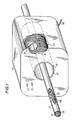
- detector 10 is mounted on a cigarette making maching (not shown) at a point beyond the formation point of cigarette rod 11 and preferably before rod 11 is cut into individual cigarettes.
- rod 11 has an outer layer of cigarette paper 12 wrapped around tobacco filler 13.
- An exemplary metal shaving is shown at 14.
- Detector 10 includes a bore 15 through which rod 11 passes.
- bore 15 is a passtube made of a high-molecular-weight methacrylate plastic such as that sold under the trademark LEXAN®.
- a conductive wire is wound 40 times around passtube 16 to form a multiturn inductor coil 17 which is connected to the detector circuitry (not shown in FIG. 1).
- a cable 18 provides power to the detector circuitry and conducts the signals generated by the detector circuitry to, for example, the reject system (not shown) of the cigarette making machine.
- a light-emitting diode 19A is illuminated whenever detector 10 is operational.
- a second light-emitting diode 19B illuminates whenever metal is detected.
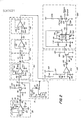
- FIG. 2 A preferred embodiment of the detector circuitry is shown in FIG. 2.
- the oscillator circuit of detector 10 is shown in the dashed rectangle 20.
- Operational amplifier 24, inductor 17, and capacitors 21-23 are configured as shown to form an oscillator which preferably has a characteristic frequency in the range from 650 to 900 kHz, preferably about 760 kHz, under nominal conditions (i.e., no metal in the passtube 16).
- Inductor coil 17 of detector 10 is located in the negative feedback loop of operational amplifier 24 which is biased by capacitor 21 to produce an output signal oscillating about a baseline (DC component) of +5 volts under nominal conditions.
- Voltage source 27, typically +12 volts, fed across pull up capacitor 26 is added to the output of amplifier 24 at node 25.
- a representative output signal 30 produced at node 25 by circuit portion 20 is shown graphically in FIG. 3.
- Signal 30 ordinarily has amplitude A, typically about 6 volts, peak to peak, and a characteristic frequency of about 760 kHz.
- amplitude A typically about 6 volts
- peak to peak peak to peak
- a characteristic frequency typically about 760 kHz.
- the change of inductance of coil 17 has two effects of consequence in the present invention. First, it changes the impedance in the negative feedback loop of amplifier 24 which changes the gain of amplifier 24. Changing the gain changes the amplitude of the AC component of signal 30. Second, the change in inductance of coil 27 disturbs the steady state charge of capacitor 26, allowing signal current from voltage source 27 (+12v) to flow through capacitor 26, coil 17 and capacitor 21 to ground. This changes the DC bias point of amplifier 24, thus altering the DC baseline component of signal 30. The change of inductance also causes a frequency change which plays no role in the present invention.
- the presence of an exemplary metallic particle passing through detector 10 causes the output signal 30 to change from the nominal condition shown at time interval t0-t1, to an abnormal condition, shown at time interval t1-t2, and thereafter to return to the nominal condition, shown at time interval t2-t3.
- the amplitude of the AC component of signal 30 increases from A to B, and the DC baseline component increases by ⁇ , for a total absolute change of ⁇ .
- the detector apparatus more specifically the analytical circuitry described below, is set to detect when output signal 30 is above or crosses a threshhold signal level represented by C, then the detector will indicate the presence of the exemplary metallic particle 14 causing such a change.
- signal 30, as depicted in time interval t1-t2 would result in the detection of a metal object.
- oscillator circuit 20 did not alter the DC baseline component as well as the AC component, the peak 31 of signal 30 would not exceed C for the same exemplary metallic particle 14.
- the circuit shown in FIG. 2 increases detector sensitivity by shifting both the DC baseline component and the amplitude of the AC component.
- the analytical circuitry shown in FIG. 2 comprises filter circuit 90 for filtering the analyzing signal 30 and providing a filtered signal corresponding to the baseline and amplitude of the output signal including both nominal and abnormal conditions, comparative circuit 140 for comparing the filtered signal to a threshold signal and providing an output signal representing the detection of a metal particle when the filtered signal is greater than the threshold value, and a metal-detected indicator 200 which indicates that a metallic particle has been detected, e.g., by illuminating light emitting diode 19B, providing a reject trigger signal, or both.
- the analytical circuitry typically also includes indicator circuit 70 for indicating when the device is operational, e.g., by illuminating light emitting diode 19A.
- the detection of a metal particle causes a baseline and amplitude shift in signal 30.
- the DC baseline and AC amplitude shift combine to modulate onto the characteristic frequency a lower frequency signal, typically with a positive-going pulse and a negative-going pulse in tandem, the pulses being of about equal magnitude. Any frequency shift to the characteristic frequency caused by the metal particle can be ignored because any shift is small and frequencies near and above the characteristic frequency are filtered out as explained below. By substantially suppressing the characteristic frequency, the pulses corresponding to the DC baseline and AC amplitude shift remain and, after amplification, can be readily detected.
- Incorporating the DC baseline shift to the change provides greater sensitivity, permitting detection of extremely small non-ferromagnetic and ferromagnetic particles.
- the DC baseline shift may be momentary, and may be restored to the nominal baseline by capacitor 26, which begins charging shortly after it discharges, depending on its time constant. Moreover, AC coupling capacitors are used to minimize any DC baseline shift injected by power fluctuation, amplification, or other equipment interference. Because the analytical circuit looks at the onset of the change, even a momentary shift in DC baseline will be detected in addition to the AC amplitude change, and any subsequent suppression of the DC base-line shift by a coupling capacitor does not affect detection of metallic particles.
- signal 30 is AC coupled by capacitor 50 and passed across resistors 52 and 54 to the base of buffer transistor 56.
- Voltage source 58 typically a +12 volt source, is fed through resistor 60 to the collector of transistor 56, and the emitter of transistor 56 is grounded.
- Signal 30 thus turns on transistor 56 and the signal generated at node 59 is AC coupled by capacitor 62 to provide a basically sinusoidal output signal 30 at node 64.
- This signal is then AC coupled by capacitor 69 to an optional indicator circuit 70 which comprises driver transistor 72, light emitting diode (LED) 19A, voltage source 76 (+12V), and resistors 75, 77 and 79 configured as shown. Transistor 72 is biased on when no signal is input to the base of transistor 72.
- LED light emitting diode
- Signal 30 at node 64 is also fed to filter circuit 90 which comprises high gain amplifier 100, passive low pass filter 110, amplifier 120, and active low pass filter 130.
- Amplifier 100 provides high gain inverted amplification of signal 30 in order to be able to detect the small changes in DC baseline and AC amplitude riding on the characteristic frequency after amplified signal 30 is low pass filtered.
- Amplifier 100 includes operational amplifier 102, which has control voltage sources 105a at ⁇ 12 volts and 105b at -12 volts fed across respective grounded capacitors 103a and 103b to suppress noise, a grounded non-inverting input, resistor 104 in the feedback loop, and input resistor 106 to the inverting input.
- the values of resistors are selected to provide a high gain, for example, about 47.
- Amplified signal 30 is then AC coupled by capacitor 108 to passive low pass filter 110 including resistor 112 and capacitor 114 having values selected to pass only frequencies below the characteristic frequency.
- Filter 100 is tuned to reject (or pass to ground) as much of the characteristic frequency and higher frequencies as possible, including any frequency shift caused by the presence of a metal particle, while minimizing rejection of the lower frequency signal pulse components of output signal 30 caused by the metal particle.
- the bandwidth of the lower frequency signals may vary depending upon the size of the particle. The longer the permeability is changed, the more it affects the bandwidth, up to a point. Signals for larger particles have been found from 18 kHz as compared to just below 750 kHz for extremely small particles. Pulse width times as large as 1.0 millisecond have been found. It is believed that the charge stored in capacitor 114 may aid in increasing the pulse width due to a temporary discharge at the onset of an abnormal output signal 30 increasing the duration of the abnormal condition.
- the filtered signal output from filter 110 is then amplified by amplifier 120 which consists of operational amplifier 122 having a grounded non-inverting input, feedback resistor 124, and inverting input resistor 126.
- the values of resistors 124 and 126 may be selected to provide a gain of about 54.
- the amplified signal 30 output from amplifier 120 is coupled by input resistor 131 to active low pass filter 130 tuned to suppress the characteristic frequency (and higher frequencies) and noise.
- Filter 130 is configured as shown and includes operational amplifier 132, and filtered and amplified signal 30 is input both to the non-inverting input through resistor 136 and across grounded capacitor 134, and to the inverting input by capacitor 138.
- Comparator 140 includes operational amplifier 142 having at its inverting input a bias or threshhold signal which is provided by a +12 volt source across resistor 146 in parallel with a -12 volt source across resistor 148, which signals are added and passed through a low pass filter including resistor 150 and capacitor 152 to filter out noise.
- the values of resistors 146 and 148 may be adjusted to set the comparator at the selected bias or threshold voltage level.
- the AC coupled output of filter 130 is passed across grounded resistor 154 to the non-inverting input.
- the output of amplifier 142 is connected to diode 158 which is forward biased to pass the positive output signal to the base of buffer transistor 160 across resistors 161 and 163 configured as shown.
- a +12 volt source is passed across resistor 165 to the collector of transistor 160.
- the bias voltage causes amplifier 142 to have a negative output which open-circuits diode 158 and turns buffer transistor 160 off.
- a metallic particle causes a shift in the DC baseline and AC amplitude of signal 30.
- the remaining pulse components shown in FIG. 3A, are input to comparator 142.
- comparator 142 When the voltage value of the pulse components rises above the bias or threshold voltage, comparator 142 provides a positive output which closes diode 158 and turns on buffer transistor 160.
- comparator 142 turns off, which opens diode 158 and turns off buffer transistor 160.
- comparator 142 puts out a positive square pulse signal at node 162 and transistor 160 provides a respective negative square pulse signal at node 164, both pulses corresponding to the detected metal particle.
- the signal from node 164 is input to metal-detected indicator circuit 200 which comprises a single shot output circuit based on a 555 clock type timer 202 having a 5.2 msec pulse width.
- Timer 202 is configured as shown with a +12 volt source, resistor 204, and capacitors 206, 208, and 210 to provide a positive pulse upon the detection of the falling edge of the signal from node 164.
- the positive pulse output of timer 202 is input to the base of driver transistor 220 across resistors 222 and 224.
- the driver transistor emitter is grounded and the collector is biased by a +12 volt source fed through resistor 226 in series with light emitting diode 19B which is oriented so that when timer 202 output is at the nominal condition, driver transistor 220 is off, and LED 19B is biased open and off.
- a pulse is output from timer 202, it turns on transistor 220 which closes LED 19B which in turn emits light for the length of the pulse width.
- the pulse also causes the signal at node 230 to go from the bias voltage level, corresponding to a logical high state of e.g., +12 volts, to a short-circuited voltage level when transistor 220 is turned on, corresponding to logical low state, e.g., +0 volts, for the duration of the pulse.
- the signal at node 230 can be used as a reject signal to input to a control circuit, typically a logic control circuit, for rejecting the sample containing the metal particle at an appropriate time and location. For example, cirgarettes corresponding to the detected pulse as indentified by the trigger signal can be rejected after the pressure drop test, whether or not the cigarette passes the pressure drop test.
- the ⁇ 12 volts power supplies may be from any conventional regulated source.
- the detector utilizes the power supply from the cigarette manufacturing maching and uses two conventional voltage regulators internal to the detector unit to provide better signal stability and reduce any noise component that might be present in the power supply of the machine or its related circuitry. Lowering the noise level enhances the sensitivity of the apparatus.
- the increased sensitivity of the metal detector of the present invention allows the detection of particles as small as 1.0 mm, which are precisely the kinds of particles not detected by previous metal detectors. Moreover, it also readily detects both ferromagnetic and non-ferromagnetic particles.
- the detector also works best at the high speeds characteristic of cigarette making machines e.g., 1,033 feet per minute, because of the dynamic action of the oscillating circuit. In fact, larger pieces of metal inserted very slowly into a detector of the present invention may not be detected because, at low speeds, any inductance change caused by the entry of the metal object, and the change in capacitance affecting the DC bias, may be integrated out over the time constant of the oscillator circuit. With appropriate redesign and adjustment of time constants, however, detectors of the present invention may be adapted for use with slower moving samples.
- a metal detector which can be used to detect small particles moving at speeds such as those found in a cigarette maker.
Landscapes
- Physics & Mathematics (AREA)
- Life Sciences & Earth Sciences (AREA)
- General Physics & Mathematics (AREA)
- General Health & Medical Sciences (AREA)
- Remote Sensing (AREA)
- Chemical & Material Sciences (AREA)
- Engineering & Computer Science (AREA)
- Health & Medical Sciences (AREA)
- Immunology (AREA)
- Biochemistry (AREA)
- Analytical Chemistry (AREA)
- Pathology (AREA)
- Dispersion Chemistry (AREA)
- Electromagnetism (AREA)
- Toxicology (AREA)
- Environmental & Geological Engineering (AREA)
- Geology (AREA)
- General Life Sciences & Earth Sciences (AREA)
- Geophysics (AREA)
- Investigating Or Analyzing Materials By The Use Of Magnetic Means (AREA)
Applications Claiming Priority (2)
| Application Number | Priority Date | Filing Date | Title |
|---|---|---|---|
| US927276 | 1986-11-04 | ||
| US06/927,276 US4839602A (en) | 1986-11-04 | 1986-11-04 | Means for detecting metal in a stream of particulate matter |
Publications (3)
| Publication Number | Publication Date |
|---|---|
| EP0267021A2 true EP0267021A2 (de) | 1988-05-11 |
| EP0267021A3 EP0267021A3 (en) | 1989-03-22 |
| EP0267021B1 EP0267021B1 (de) | 1992-01-22 |
Family
ID=25454502
Family Applications (1)
| Application Number | Title | Priority Date | Filing Date |
|---|---|---|---|
| EP87309762A Expired EP0267021B1 (de) | 1986-11-04 | 1987-11-04 | Gerät zur Metalldetektion in einem Fluss von Masseteilchen |
Country Status (4)
| Country | Link |
|---|---|
| US (1) | US4839602A (de) |
| EP (1) | EP0267021B1 (de) |
| AU (1) | AU593954B2 (de) |
| DE (1) | DE3776272D1 (de) |
Cited By (5)
| Publication number | Priority date | Publication date | Assignee | Title |
|---|---|---|---|---|
| WO1990007705A1 (en) * | 1988-12-27 | 1990-07-12 | United Technologies Corporation | Arrangement for detecting metallic particles carried by a fluid |
| RU2119985C1 (ru) * | 1997-07-31 | 1998-10-10 | Орловский государственный технический университет | Способ обнаружения металлических частиц в движущемся материале |
| WO2004104561A1 (de) * | 2003-05-21 | 2004-12-02 | Bayer Technology Services Gmbh | Verfahren und vorrichtung zur messung des gehaltes an ferromagnetischen partikeln in flüssigkeits-suspensionen, aerosolen oder feststoff-gemischen |
| EP3474451A1 (de) * | 2017-10-19 | 2019-04-24 | Imst Gmbh | Sensorvorrichtung, detektionsverfahren für eine sensorvorrichtung und verwendung einer sensorvorrichtung |
| DE202017007460U1 (de) | 2017-10-19 | 2021-09-09 | Imst Gmbh | Sensorvorrichtung |
Families Citing this family (11)
| Publication number | Priority date | Publication date | Assignee | Title |
|---|---|---|---|---|
| US5476108A (en) * | 1990-04-05 | 1995-12-19 | R. J. Reynolds Tobacco Company | Method and apparatus for detecting foreign matter within a layer of tabacco |
| GB2324154B (en) * | 1997-04-01 | 2001-05-02 | Michael John Hutchings | Electromagnetic detector for measuring magnetic or conductive properties |
| US6043639A (en) * | 1997-12-01 | 2000-03-28 | Celestica International Inc. | Method and apparatus for real-time detection of airborne conductive contaminants |
| JP6572519B2 (ja) * | 2013-04-23 | 2019-09-11 | 株式会社リコー | 透磁率検知器、現像装置及び画像形成装置 |
| JP5915953B2 (ja) * | 2014-03-05 | 2016-05-11 | パナソニックIpマネジメント株式会社 | 異物検出装置、送電装置、受電装置、および無線電力伝送システム |
| EP3009866B1 (de) * | 2014-03-05 | 2022-05-04 | Panasonic Intellectual Property Management Co., Ltd. | Fremdkörperdetektor, stromsender, stromempfänger und drahtloses stromübertragungssystem |
| DE102016115098A1 (de) * | 2016-08-15 | 2018-02-15 | Hauni Maschinenbau Gmbh | Messvorrichtung und Verfahren zum Erkennen von elektrisch leitenden Elementen in Produkten sowie eine Maschine zum Herstellen von Produkten der Tabak verarbeitenden Industrie |
| US11017992B2 (en) * | 2019-09-11 | 2021-05-25 | Agilent Technologies, Inc. | AC-coupled system for particle detection |
| WO2021130196A1 (en) * | 2019-12-23 | 2021-07-01 | Philip Morris Products S.A. | Method and apparatus for inspecting an inductively heatable aerosol-generating article for the presence of a susceptor and a desired article alignment |
| KR20230091948A (ko) * | 2020-10-21 | 2023-06-23 | 필립모리스 프로덕츠 에스.에이. | 로드 형상 물품의 품질 관리를 위한 검사 디바이스 |
| BR112023005291A2 (pt) * | 2020-10-21 | 2023-05-02 | Philip Morris Products Sa | Método de inspeção de artigos em forma de coluna |
Family Cites Families (35)
| Publication number | Priority date | Publication date | Assignee | Title |
|---|---|---|---|---|
| US2048591A (en) * | 1934-07-23 | 1936-07-21 | Harry L Berry | Metal detecting device |
| US2550607A (en) * | 1948-02-13 | 1951-04-24 | Frank M Shoemaker | Electronic metal detector |
| US2587631A (en) * | 1948-05-21 | 1952-03-04 | American Can Co | Apparatus for measuring and detecting magnetic objects |
| US2580670A (en) * | 1948-06-28 | 1952-01-01 | Radio Frequency Lab Inc | Metal detector |
| US2709785A (en) * | 1951-05-03 | 1955-05-31 | Robertshaw Fulton Controls Co | Measurement of conductivity of liquids |
| US2863546A (en) * | 1956-03-19 | 1958-12-09 | Best Foods Inc | Magnetic flux monitoring apparatus |
| US3030576A (en) * | 1958-04-24 | 1962-04-17 | Tno | Circuit for measuring self-inductances and capacitances and changes thereof |
| US3237155A (en) * | 1962-03-08 | 1966-02-22 | Lab For Electronics Inc | Vehicle detector |
| GB1092362A (en) * | 1963-05-23 | 1967-11-22 | David Theodore Nelson Williams | Improvements in detectors for electrically conductive or magnetic particles |
| US3278809A (en) * | 1963-10-16 | 1966-10-11 | Gen Cable Corp | Tinsel splice detector |
| CH421237A (de) * | 1964-02-05 | 1966-09-30 | Ebauches Sa | Näherungsdetektor |
| US3375493A (en) * | 1965-06-30 | 1968-03-26 | Gen Precision Systems Inc | Inductive loop presence detector |
| FR1507154A (fr) * | 1965-08-20 | 1967-12-29 | Telemecanique Electrique | Détecteur à oscillateur |
| US3460000A (en) * | 1965-11-16 | 1969-08-05 | Allen Bradley Co | Stabilized control circuit |
| US3721821A (en) * | 1970-12-14 | 1973-03-20 | Abex Corp | Railway wheel sensor |
| US3935542A (en) * | 1972-01-22 | 1976-01-27 | Robert Buck | Contactless oscillator-type proximity sensor with constant-voltage impedance |
| US3727075A (en) * | 1972-02-24 | 1973-04-10 | Ibm | Missing type detector |
| US3747011A (en) * | 1972-09-21 | 1973-07-17 | R Buck | Metal detector including proximity-responsive oscillator with feedback-stabilized gain |
| US3747012A (en) * | 1972-09-21 | 1973-07-17 | R Buck | Contactless oscillator-type proximity sensor with adjustable hysteresis |
| US3747010A (en) * | 1972-09-21 | 1973-07-17 | R Buck | Power supply for oscillator circuit of contactless proximity indicator |
| US3809998A (en) * | 1973-02-01 | 1974-05-07 | Magnetic Analysis Corp | Current regulator for pulse eddy current tester |
| US3961238A (en) * | 1975-01-22 | 1976-06-01 | Robert F. Gardiner | Selective metal detector circuit having dual tuned resonant circuits |
| US4138709A (en) * | 1975-10-22 | 1979-02-06 | Square D Company | Proximity switch |
| DE2711877C3 (de) * | 1977-03-18 | 1979-09-13 | Robert 7995 Neukirch Buck | Elektronisches Schaltgerät |
| US4130792A (en) * | 1977-09-30 | 1978-12-19 | Sullivan John W | Metal detector with feedback tuning |
| US4220499A (en) * | 1978-10-04 | 1980-09-02 | Westvaco Corporation | Method for determining the relative quantity of shives in a stream of fibrous particles |
| US4291280A (en) * | 1978-11-15 | 1981-09-22 | Sybron Corporation | AC Generator system having stabilized sensitivity for sensing the presence or absence of a conductive object |
| US4257001A (en) * | 1979-04-13 | 1981-03-17 | John G. Abramo | Resonant circuit sensor of multiple properties of objects |
| EP0062396A3 (de) * | 1981-03-26 | 1983-06-22 | Environmental Products Corporation | Aluminiumbüchsendetektor |
| AT377650B (de) * | 1982-03-30 | 1985-04-10 | Siemens Ag Oesterreich | Oszillatorschaltung |
| DE96568T1 (de) * | 1982-06-09 | 1984-05-10 | Deere & Co., 61265 Moline, Ill. | Metallsuchanordnung. |
| DE3225193A1 (de) * | 1982-07-06 | 1984-01-12 | Gebhard Balluff Fabrik feinmechanischer Erzeugnisse GmbH & Co, 7303 Neuhausen | Induktiver naeherungsschalter |
| US4613815A (en) * | 1983-04-27 | 1986-09-23 | Pall Corporation | Electromagnetic detector for metallic materials having an improved phase detection circuit |
| DE3327329C2 (de) * | 1983-07-29 | 1987-02-12 | Robert 7995 Neukirch Buck | Elektronisches, vorzugsweise berührungslos arbeitendes Schaltgerät |
| US4613830A (en) * | 1984-07-27 | 1986-09-23 | Omron Tateisi Electronics, Co. | Proximity switch having variable gain oscillator |
-
1986
- 1986-11-04 US US06/927,276 patent/US4839602A/en not_active Expired - Lifetime
-
1987
- 1987-11-04 AU AU80650/87A patent/AU593954B2/en not_active Ceased
- 1987-11-04 EP EP87309762A patent/EP0267021B1/de not_active Expired
- 1987-11-04 DE DE8787309762T patent/DE3776272D1/de not_active Expired - Fee Related
Cited By (6)
| Publication number | Priority date | Publication date | Assignee | Title |
|---|---|---|---|---|
| WO1990007705A1 (en) * | 1988-12-27 | 1990-07-12 | United Technologies Corporation | Arrangement for detecting metallic particles carried by a fluid |
| AU635516B2 (en) * | 1988-12-27 | 1993-03-25 | United Technologies Corporation | Arrangement for detecting metallic particles carried by a fluid |
| RU2119985C1 (ru) * | 1997-07-31 | 1998-10-10 | Орловский государственный технический университет | Способ обнаружения металлических частиц в движущемся материале |
| WO2004104561A1 (de) * | 2003-05-21 | 2004-12-02 | Bayer Technology Services Gmbh | Verfahren und vorrichtung zur messung des gehaltes an ferromagnetischen partikeln in flüssigkeits-suspensionen, aerosolen oder feststoff-gemischen |
| EP3474451A1 (de) * | 2017-10-19 | 2019-04-24 | Imst Gmbh | Sensorvorrichtung, detektionsverfahren für eine sensorvorrichtung und verwendung einer sensorvorrichtung |
| DE202017007460U1 (de) | 2017-10-19 | 2021-09-09 | Imst Gmbh | Sensorvorrichtung |
Also Published As
| Publication number | Publication date |
|---|---|
| AU593954B2 (en) | 1990-02-22 |
| EP0267021B1 (de) | 1992-01-22 |
| EP0267021A3 (en) | 1989-03-22 |
| AU8065087A (en) | 1988-05-05 |
| US4839602A (en) | 1989-06-13 |
| DE3776272D1 (de) | 1992-03-05 |
Similar Documents
| Publication | Publication Date | Title |
|---|---|---|
| US4839602A (en) | Means for detecting metal in a stream of particulate matter | |
| DE3513664C2 (de) | ||
| US5293980A (en) | Coin analyzer sensor configuration and system | |
| DE69220953T2 (de) | Vorrichtung zur unterscheidung von münzen | |
| EP0045942B1 (de) | Anordnung zur Feststellung von Werkzeugverschleiss | |
| EP3132248B1 (de) | Partikelzähler und -klassifizierungssystem | |
| DE69504719T2 (de) | Vorrichtung zur Messung der Drehzahl eines rotierenden Teiles | |
| JP2001509366A (ja) | バンド検査を含むシガレット製造機 | |
| EP1646015A3 (de) | Vorrichtung und Verfahren zur Münzerkennung | |
| CA2169443A1 (en) | Magnetic flowmeter with empty pipe detector | |
| DE3612573A1 (de) | Detektionssystem fuer eisenmetallische partikel | |
| AT504527A4 (de) | Verfahren und vorrichtung zum unterscheiden von ein elektromagnetisches wechselfeld beeinflussenden objekten, insbesondere metallobjekten | |
| EP3497438B1 (de) | Messvorrichtung und verfahren zum erkennen von elektrisch leitenden elementen in produkten sowie eine maschine zum herstellen von produkten der tabak verarbeitenden industrie | |
| DE69311812T2 (de) | Münzprüfer | |
| US2729214A (en) | Detecting and control apparatus | |
| EP1836484B9 (de) | Messvorrichtung und -verfahren zur erkennung von fremdkörpern in tabak | |
| DE69132520T3 (de) | Vorrichtung und Verfahren zum Unterscheiden von Münzen | |
| US3381217A (en) | Detectors for electrically conductive particles | |
| JP3613770B2 (ja) | 流体の流れの中の存在物の提示を機械的,電子的に修正するための方法と装置 | |
| US4436427A (en) | Photoelectric measurement of moving filamentary material | |
| CA1122669A (en) | Magnetic detector | |
| EP1347311B1 (de) | Verfahren zum Detektieren von Objekten, insbesondere von Metallobjekten | |
| GB1524853A (en) | Tobacco density testing method and apparatus | |
| DE2840358A1 (de) | Detektorgeraet mit einem an einer fluessigkeitsleitung angeordneten induktiven sensor | |
| DE10213115A1 (de) | Verfahren zum Aussortieren von Metallobjekten bzw. eine Sortieranlage, ein Detektor sowie eine Schaltungsanordnung hierfür |
Legal Events
| Date | Code | Title | Description |
|---|---|---|---|
| PUAI | Public reference made under article 153(3) epc to a published international application that has entered the european phase |
Free format text: ORIGINAL CODE: 0009012 |
|
| AK | Designated contracting states |
Kind code of ref document: A2 Designated state(s): BE CH DE GB LI NL |
|
| RAP1 | Party data changed (applicant data changed or rights of an application transferred) |
Owner name: PHILIP MORRIS PRODUCTS INC. |
|
| PUAL | Search report despatched |
Free format text: ORIGINAL CODE: 0009013 |
|
| AK | Designated contracting states |
Kind code of ref document: A3 Designated state(s): BE CH DE GB LI NL |
|
| 17P | Request for examination filed |
Effective date: 19890714 |
|
| 17Q | First examination report despatched |
Effective date: 19910228 |
|
| GRAA | (expected) grant |
Free format text: ORIGINAL CODE: 0009210 |
|
| AK | Designated contracting states |
Kind code of ref document: B1 Designated state(s): BE CH DE GB LI NL |
|
| REF | Corresponds to: |
Ref document number: 3776272 Country of ref document: DE Date of ref document: 19920305 |
|
| PG25 | Lapsed in a contracting state [announced via postgrant information from national office to epo] |
Ref country code: GB Effective date: 19921104 |
|
| PLBE | No opposition filed within time limit |
Free format text: ORIGINAL CODE: 0009261 |
|
| STAA | Information on the status of an ep patent application or granted ep patent |
Free format text: STATUS: NO OPPOSITION FILED WITHIN TIME LIMIT |
|
| PG25 | Lapsed in a contracting state [announced via postgrant information from national office to epo] |
Ref country code: LI Effective date: 19921130 Ref country code: CH Effective date: 19921130 Ref country code: BE Effective date: 19921130 |
|
| 26N | No opposition filed | ||
| BERE | Be: lapsed |
Owner name: PHILIP MORRIS PRODUCTS INC. Effective date: 19921130 |
|
| PG25 | Lapsed in a contracting state [announced via postgrant information from national office to epo] |
Ref country code: NL Effective date: 19930601 |
|
| GBPC | Gb: european patent ceased through non-payment of renewal fee |
Effective date: 19921104 |
|
| NLV4 | Nl: lapsed or anulled due to non-payment of the annual fee | ||
| REG | Reference to a national code |
Ref country code: CH Ref legal event code: PL |
|
| PG25 | Lapsed in a contracting state [announced via postgrant information from national office to epo] |
Ref country code: DE Effective date: 19930803 |