EP0267101A1 - Vorrichtung zum koordinierten Steuern zweies Durchflussregelorgane für Strömungsmittel - Google Patents
Vorrichtung zum koordinierten Steuern zweies Durchflussregelorgane für Strömungsmittel Download PDFInfo
- Publication number
- EP0267101A1 EP0267101A1 EP87402403A EP87402403A EP0267101A1 EP 0267101 A1 EP0267101 A1 EP 0267101A1 EP 87402403 A EP87402403 A EP 87402403A EP 87402403 A EP87402403 A EP 87402403A EP 0267101 A1 EP0267101 A1 EP 0267101A1
- Authority
- EP
- European Patent Office
- Prior art keywords
- stroke
- cam
- control member
- lever
- adjustment
- Prior art date
- Legal status (The legal status is an assumption and is not a legal conclusion. Google has not performed a legal analysis and makes no representation as to the accuracy of the status listed.)
- Withdrawn
Links
Images


Classifications
-
- B—PERFORMING OPERATIONS; TRANSPORTING
- B60—VEHICLES IN GENERAL
- B60H—ARRANGEMENTS OF HEATING, COOLING, VENTILATING OR OTHER AIR-TREATING DEVICES SPECIALLY ADAPTED FOR PASSENGER OR GOODS SPACES OF VEHICLES
- B60H1/00—Heating, cooling or ventilating devices
- B60H1/00642—Control systems or circuits; Control members or indication devices for heating, cooling or ventilating devices
- B60H1/00814—Control systems or circuits characterised by their output, for controlling particular components of the heating, cooling or ventilating installation
- B60H1/00821—Control systems or circuits characterised by their output, for controlling particular components of the heating, cooling or ventilating installation the components being ventilating, air admitting or air distributing devices
- B60H1/00835—Damper doors, e.g. position control
- B60H1/00857—Damper doors, e.g. position control characterised by the means connecting the initiating means, e.g. control lever, to the damper door
Definitions
- the invention relates to a device for the coordinated control of two respective flow control members for two streams of fluids, in particular a stream of cold air and a stream of air heated by passing in contact with an exchanger. heat, intended to be sent to a ventilation and heating outlet of the passenger compartment of a motor vehicle.
- the invention aims to allow the user to vary the flow rate and the temperature of the air supplied by the air vent by a single movement of a control member.
- the device comprises a control member which can be moved in a unique course and mechanical transmission means for driving the adjustment members according to the movement of the control member so that over part of the race a first adjusting member remains practically in a minimum opening state while the second adjusting member passes substantially from a minimum opening state to a maximum opening state or vice versa and while on another part of the stroke the first adjustment member passes substantially from a minimum opening state to a maximum opening state or vice versa.
- the state minimum opening corresponds substantially to a closed state, that is to say of zero flow.
- the two adjustment members are simultaneously in their minimum opening state, this point being able to be an intermediate point or an extreme point of the race.
- the adjustment members are flaps that can pivot so as to close a fluid passage to a variable degree.
- At least one of the flaps can pivot in one direction between an extreme minimum opening position and an extreme maximum opening position, or between two extreme positions corresponding to a minimum or maximum opening state, passing through at least one intermediate position corresponding to the opposite state of maximum or minimum opening.
- the degree of opening of the shutter can vary gradually during the whole of its movement, or the shutter can remain practically in a state of minimum opening during a portion of its movement.
- the flap can pivot in a first direction from an extreme minimum opening position to an extreme maximum opening position, then in the opposite direction from the maximum opening position to the minimum opening position.
- the transmission means comprise a pivoting drive cam corresponding to the stroke of the control element to drive one of the adjustment members by means of a pivoting element , the cam being able to have at least one substantially circumferential working surface cooperating with the pivoting element to keep the latter fixed, and at least one substantially radial working surface cooperating with the pivoting element to rotate the latter.
- the drive cam can p represent a substantially circumferential work surface connecting between it a substantially radial work surface and an oblique work surface, these work surfaces cooperating with the pivoting element to maintain the latter in a position of maximum opening on an intermediate portion of the stroke and to gradually bring it to a minimum opening position at both ends of the stroke.
- oblique or inclined working surface is meant a surface which cuts the spokes of the cam at a non-right angle.
- the pivoting element associated with the driving cam which has a circumferential working surface and a radial working surface
- Another embodiment of the drive cam provides two working surfaces inclined in opposite directions with respect to its radius, cooperating with the pivoting element to drive the latter in a back and forth movement during the stroke of the 'regulator.
- the transmission means comprise a motor lever pivoting in correspondence with the stroke of the control member and connected by a connecting rod to a crank driving one of the adjustment elements so that during said stroke the crank performs a back and forth movement between two angular positions corresponding respectively to the minimum opening and maximum opening states of the associated adjusting element.
- the another adjusting member is driven in a continuous movement with the driving cam or the engine lever.
- the same drive cam may have six working surfaces, namely two substantially circumferential working surfaces connected together by a substantially radial working surface, cooperating with a first pivoting element associated with one of the adjustment members, and a substantially circumferential work surface connecting between it a substantially radial work surface and an oblique work surface, cooperating with a second pivoting element associated with the other adjustment member.
- the driving cam driving the adjusting member by means of its working surfaces also constitutes a lever driving the other adjusting member by means of a connecting rod.
- the transmission means comprise a motor lever cooperating with a pivoting cam, which drives one of the adjustment members, by working surfaces thereof, one of which at least extends circumferentially relative to the lever when it is engaged with the latter to maintain the cam in a fixed position over a portion of the travel of the member control, and at least one other of which extends radially or obliquely relative to the lever when it is engaged with the latter in order to pivot the cam on another portion of said stroke.
- the device may include a motor for driving the adjustment members by means of these, and an on / off selector, the motor bringing the two adjustment members to their position. minimum open state when the selector is in the stop position and bringing them to the states defined by the position of the control member when the selector is in the on position.
- the invention also relates to an installation for ventilating and heating the passenger compartment of a motor vehicle, comprising a control device as defined above, and means for interrupting a supply of heat to a heat exchanger. heat used to heat one of the air currents when the control member is in a stop position for which the hot air flow control member is in a minimum open state.
- the interruption means can be implemented automatically when the control member is in the stop position.
- the interrupting means can be manual, the control member being able to be moved from its stopped position only if the interrupting means are out of service, that is to say do not interrupt the supply of heat to the heat exchanger.
- FIG. 1 illustrates part of an installation for ventilating and heating the passenger compartment of a motor vehicle.
- a pipe 51 brings a stream of cold air taken from outside the vehicle to an adjustment and mixing region 50.
- a heat exchanger 4 such as a radiator through which hot water from 'A vehicle engine cooling circuit is interposed on a line 52, where a cold air flow circulates upstream of the exchanger, the air heated by the radiator is also brought to the adjustment and mixing region 50.
- a pipe 53 channels a current of air from region 50 to one or more air vents and heating of the passenger compartment.
- the flow rate and the temperature of the air in the pipe 53 are a function of the positions of two pivoting flaps 1 and 2, which can block the outlet of the pipe 51 and that of the pipe 52 respectively to a variable degree, downstream of the radiator. 4.
- the flaps 1 and 2 are driven in a coordinated manner by a driving cam 3, the angular position of which is defined by a control member, not shown, located on the dashboard of the vehicle, and which the user can move according to a determined stroke in a single movement.
- the cam 3 has a slot 30 through which a lug 21 which extends parallel to the pivot axis A3 of the cam 3 from a lever 20 which can itself pivot around an axis A2 parallel to the axis A3.
- the lateral edges of the slot 30 defined feels working surfaces of the cam cooperating with the lug 21 to determine the angular position of the lever 20 as a function of that of the cam.
- a first substantially circumferential work surface 31 extends substantially in an arc between a end a and an intermediate point b of the slot. To this first working surface is connected a second substantially radial working surface 32 extending along a portion of radius between point b and a point c. Finally, a third substantially circumferential working surface 33 extends in an arc from point c to the second end d of the slot 30.
- the lug 21 is located at the end a of the slot 30 of the cam.
- the shutter 2, integral with the lever 20, is in a position for closing the passage between the pipe 52 and the region 50.
- the working surface 31 cooperates with the lug 21 to first of all keep the latter at a constant distance from the axis A3, so that the lever 20 and the flap 2 remain fixed.
- the lug 21 reaches point b of the slot 30, it cooperates with the radial working surface 32 which causes it to approach the axis A3.
- the lever 20 and the flap then rotate clockwise, gradually opening the passage between the pipe 52 and the region 50.
- the flap 2 takes the position illustrated in phantom , corresponding to a state of maximum opening of the passage between the pipe 52 and the region 50. This position is maintained during the final phase of the movement of the cam, during which the lug traverses the arc cd by cooperating with the work surface 33.
- the final position of the cam 3 and that of the lever 20 are also illustrated in phantom.
- Cam 3 also has teeth in an arc 34 cooperating with a pinion 10 which can pivot about an axis A1 parallel to the axis A3 and of which the flap 1 is integral.
- the pinion 10 and the flap 1 pivot continuously in a clockwise direction.
- the flap 1 is in the position shown in solid lines where it almost completely closes the passage between the pipe 51 and the adjustment and mixing region 50.
- position b of the control member and of the cam corresponds an intermediate position of the flap 1, shown in phantom and marked 1b, for which the degree of opening of the passage is maximum.
- the extreme position d of the cam corresponds to an extreme position 1d of the lever 1 for which the passage is again closed.
- the shutter 1 has two substantially flat parts 11 and 12 which are connected to each other at an obtuse angle at the level of the axis A1, and whose free edges cooperate with stops 55 of the wall of the pipe 51 to provide a tight closure of the latter in the two extreme positions of the flap.
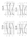
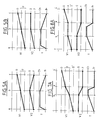
- FIG. 1A illustrates the movements of the flaps as they have just been described, and the resulting temperature of the air sent to the air vents through the pipe 53.
- the three curves marked V1, V2 and T represent respectively the angular position of the shutter 1, that of the shutter 2 and the air temperature, plotted on the ordinate, as a function of the position of the control member.
- the flap 1 passes from an extreme closing position marked F to an extreme position closing me marked F ⁇ , passing through an intermediate maximum opening position marked O for position b of the control member.
- the flap 2 remains in an extreme closed position F on the portion ab of the stroke of the control member, then gradually changes to an extreme maximum open position O on the intermediate portion bc of the stroke , and remains in this position O on the final portion cd of the race.
- FIG. 2 relates to a variant in which flaps 101 and 102 execute the same movements and fulfill the same functions as flaps 1 and 2 in FIG. 1.
- a drive cam 103 pivoting around an axis A103 in correspondence of the stroke of a control member not shown has teeth in an arc of a circle 134 which cooperates with a pinion 110 to pivot the latter, and the flap 101 which is integral therewith, about an axis A101 in the manner described in connection of FIG. 1.
- the driving cam 103 has a slot 130 in which engages a lug 161 belonging to a second cam 106 which can pivot around an axis A106 parallel to the axes A103 and A101.
- the lateral edges of the slot 130 define working surfaces suitable for cooperating with the lug 161 to determine the angular position of the cam 106 as a function of that of the cam 103.
- a first circumferential working surface 131 extends from a end a at an intermediate point b of the slot 130, and a second radial working surface 132 extends between point b and the opposite end c of the slot 130, further away from the axis A103 than the arc ab .
- the second cam 106 in turn has a slot 160 in which engages a lug 121 belonging to a lever 120 which can pivot around an axis A102 parallel to the axis A103, and integral with the flap 102.
- the lateral edges of the slot 160 define working surfaces which cooperate with the lug 121 to determine the angular position of the lever 120 as a function of that of the cam 106.
- a radial working surface 162 extends between an end b ⁇ of the slot 160 and a intermediate point c ⁇ further from axis A106 than point b ⁇ .
- Another circumferential working surface 163 extends between point c ⁇ and the second end d ⁇ of slot 160.
- the various elements illustrated in FIG. 2 are in the positions indicated in solid lines.
- the pins 161 and 121 are respectively at the ends a and b ⁇ of the slots 130 and 160, and the two flaps are in extreme closed positions.
- the cam 103 pivots so that the lug 161 traverses the arc of a circle ab while remaining at a constant distance from the axis A103.
- the cam 106 therefore remains fixed, as does the lug 121 and the lever 120. From position b to position c of the control member, the lug 161 traverses the portion of radius bc of the cam 103 in pivoting .
- FIG. 1A The diagram of FIG. 1A remains entirely valid for the device of FIG. 2.
- the reference numbers of the radiator 204 and of the pipes 251, 252 and 253 are obtained by adding the number 200 to the reference numbers of the elements of FIG. 1 of which they are the functional equivalents.
- the flow of cold air arriving through line 251 and that of heated air arriving through line 252 are regulated by pivoting flaps 201 and 202 respectively, which are driven by a drive cam 203 which pivots about an axis A203 in correspondence with the stroke of a control member not shown.
- the cam 203 has, like the cam 3 in FIG. 1, a slot 230 crossed by a lug 211 and defining two circumferential working surfaces connected together by a radial working surface.
- the lug 211 belongs to a pivoting lever 210 integral with the shutter 201.
- the lug 211 is at the end a of the slot 230 closest to the axis A203, which corresponds to the starting position a of the control member.
- the shutter 201 is then in an extreme closed position shown in solid lines. During the travel of the closure member, the shutter 201 is driven in the same way as the shutter 2 in FIG. 1.
- a connecting rod 206 is articulated by its two ends respectively to the cam 203 and to a crank 220 which can pivot around an axis A202 parallel to the axis A203 and to the axis A201 of the shutter 201, the shutter 202 being integral with the crank 220.
- the flap 202 is in a closed position shown in solid lines.
- the articulation points of the rod 206 are chosen so that the flap 202 resumes the same closed position for the position d of the control member as for the position a. Under these conditions, during the stroke of the control member, the flap 202 passes through a maximum open position shown in broken lines, and corresponding to an alignment of the ends of the connecting rod with the axis A203, before return to its closed position.
- the references 261b, 261c and 261d respectively indicate the locations of the articulation axis 261 of the connecting rod 206 on the cam 203 for the positions b, c and d of the control member; the reference 262b, c indicates the location of the hinge pin 262 of the connecting rod and the crank 220 for the positions b and c of the control member.
- FIG. 3A is a diagram similar to that of FIG. 1A, relating to the device of FIG. 3, the curves V1 and V2 corresponding respectively to the flaps 201 and 202. Each of these flaps has an extreme closed position and an extreme maximum open position.
- the shutter for adjusting the cold air flow remains closed while the hot air flow adjustment gradually opens.
- the cold air shutter opens gradually while the hot air shutter remains substantially in its maximum opening state. The temperature of the air sent through line 253 is therefore decreasing.
- the cold air flow becomes appreciably greater than the hot air flow, so that for position c, although the hot air shutter is still practically at its opening maximum, the temperature of the mixed air is close to the temperature Fr of the cold air. Finally, on the cd portion of the stroke, the hot air shutter closes while the cold air shutter remains at its maximum opening, so that the temperature of the air sent into line 253 continues to decrease until 'at the value Fr.
- the device of FIG. 3 avoids this drawback, since hot air is sent from the start of the stroke of the element command.
- you want to obtain cold air you first receive hot air, which can be annoying in hot weather.
- This drawback can also be avoided by adding a tap to the installation to interrupt the supply of hot water to the radiator 204 when the control member is in the stop position a. In this way, when the ac portion of the stroke of the control member is traversed quickly, the radiator does not have time to heat up sufficiently to communicate to the current of air passing through it a significant increase in temperature and we get cold air directly.
- FIG. 4 represents transmission means equivalent to those of FIG. 3, leading to the same movements of the adjusting flap and consequently to an operation of the installation in accordance with the diagram of FIG. 3A.
- the transmission means comprise a drive cam 303 having a slot 330 quite similar to the slot 230 of the cam 203, and likewise driving a lever 310 secured to a not shown cold air adjustment flap, mounted in the same way as the shutter 201 in FIG. 3.
- the cam 303 also has a second slot 335 crossed by a lug 321 of a lever 320 and designed so as to communicate to the latter a movement substantially similar to that of the crank 220, the lever 320 being integral with a shutter of hot air control not shown operating in the same way as the shutter 202.
- the slot 335 defines three working surfaces, namely a first working surface 336 defined by a portion of the slot extending between a first end a and a point b, a second working surface 337 extending circumferentially between point b and a point c, and a third work surface 338 extending obliquely between point c and the second end d.
- the ends a and d are closer to the axis A303 of the cam than arc bc, and end d is further from radius ab than point c.
- the devices shown in Figures 3 and 4 can be simplified by eliminating the portion of the slot or slots of the drive cam corresponding to the cd portion of the cam of the control member, provided that means are provided, for example in the form of a hot water shut-off valve, to interrupt the supply of heat to the heat exchanger when the control member is in position c, which then constitutes its terminal position.
- the flap 401 which can pivot around an axis A401 and extends symmetrically on either side thereof, is integral with a motor lever 403 whose angular position is defined by a control member not shown .
- the flap 401 is shown in solid lines in an extreme closed position corresponding to a starting position a of the control member. For a portion ab of the stroke of the control member, the flap 401 pivots to the position indicated in phantom, its free edge 412 remaining practically in contact with a portion of revolution 456 of the wall of the pipe 451 The flap 451 thus remains practically in a closed state.
- the second flap 402 is integral with a crank 420 connected by a connecting rod 406 to the motor lever 403.
- the flap 402 is in the extreme closed position illustrated in solid lines.
- the articulation axes 461 and 462 from the connecting rod to the lever 403 and to the crank 420 respectively come in positions 461b and 462b aligned with the pivot axis A401 of the motor lever, corresponding to an extreme position d maximum opening of the flap 402 indicated in broken lines.
- FIG. 5A The diagram of the states of the flaps and the temperature of the air sent to the air vents, corresponding to FIG. 5, is shown in FIG. 5A.
- the hot air flap (curve V2) begins to open, while the cold air flap pivots while remaining in the closed state, and the temperature of the air stream obtained is substantially that of the air heated by the heat exchanger.
- This temperature is maintained up to position b corresponding to the maximum opening of the hot air shutter.
- the cold air shutter (curve V1) opens gradually and the hot air shutter gradually closes, so that the air temperature gradually decreases to that of the outside air.
- Movements of the flaps identical to those which have just been described can be obtained by replacing the lever 403, the connecting rod 406 and the crank 420 of FIG. 5 by a driving cam 503 and a lever 520 as shown in FIG. 6.
- the cam 503 has a slot 530 cooperating with a lug 521 of the lever 520.
- the slot 530 comprises two parts extending respectively between an end point a and an intermediate point b and between point b and an opposite end point c. These two slot portions are substantially symmetrical to each other with respect to the plane defined by point b and the axis of rotation A501 of the cam, and oblique with respect to this plane, the ends a and c being more closer to the axis than point b.
- the lug 521 travels through the slot 530.
- the lever 520 passes from the extreme position illustrated sure the figure in another extreme position for which the axis 522 of the lug is in position 522b.
- the lever performs the reverse movement.
- the devices illustrated in Figures 7 and 8 differ from those described above in that the stop position of the control member, for which the two adjustment flaps are in the closed position, is an intermediate position on the stroke of the 'control member, from which it must be moved in one direction to obtain a stream of cold air and in the opposite direction to obtain a stream of hot air. This avoids the drawback mentioned above consisting of first receiving cold air when hot air is desired, or vice versa.
- the cold air inlet pipe 651, the air reheating pipe 652, the mixing and adjustment region 650 and the air outlet pipe 653 are similar to the corresponding elements in FIG. 1.
- a motor lever 603 pivots about an axis A601 in correspondence with the travel of a control member not shown.
- a cold air adjustment flap 601 secured to the lever 603 extends symmetrically on either side of the axis A601.
- the flap 601 pivots from the position indicated in solid lines to a position indicated in dotted lines and denoted 601b, its free edge remaining practically adjacent to a portion of revolution 656 of the wall of the pipe 651, so that the latter remains practically closed.
- the flap 601 moves away from the wall and reaches, for the extreme position c of the control member, an extreme position of maximum opening shown in phantom and denoted 601c.
- the lever 601 also pivots in the opposite direction to reach, when the control member arrives at its extreme position b ⁇ , an extreme position of maximum opening 601b ⁇ which is identical to position 601c, except that the parts of the flap located symmetrically with respect to the pivot axis are exchanged.
- the lever 603 has a lug 631 which engages in a slot 625 of a cam 620 which can pivot around an axis A602 parallel to the axis A601.
- An adjustment flap 602 for the flow of hot air in the pipe 652 is integral with the cam 620.
- the edges of the slot 625 define working surfaces of the cam cooperating with the lug 631 to cause the cam to be driven by the lever 603.
- the edges of the slot 625 define three working surfaces 626, 627 and 628.
- the working surface 626 extends radially relative to the lever 603 in the position shown corresponding to point a of the travel of the control member.
- the corresponding portion of the slot 625 extends between an intermediate point denoted a, occupied by the lug 631 in the position illus trée, at another intermediate point b, further from axis A602 and closer to axis A601 than point a.
- An end portion of the slot 625 defining the working surface 628 extends circumferentially relative to the lever 603, still in the position illustrated, between point a and one end b ⁇ .
- the lug 631 moves in the ab portion of the slot 625 by rotating the cam 620 so as to pass the flap 602 from the extreme closed position indicated at solid line at the extreme maximum opening position indicated in phantom.
- the extreme portion of the slot 625 extending in an arc between the point b and the end c opposite the end b ⁇ takes a circumferential orientation relative to the lever 603
- the lug 631 traverses the corresponding arc of the slot while keeping the cam 620 stationary.
- FIG. 7A illustrates the operation of the installation.
- the two flaps are in a closed state for the intermediate position a of the control member.
- the hot air shutter V2 remains closed while the cold air shutter V1 opens gradually.
- the control member is operated in the opposite direction from position a, the cold air flap V1 remains closed on the portion ab of the stroke, while the hot air flap V2 gradually opens .
- a stream of hot air is thus obtained at a temperature slightly lower than that of the air leaving the radiator, with an increasing flow rate.
- the cold air shutter V1 opens gradually, while the hot air shutter V2 remains stationary, leading to a gradual reduction in the air temperature.
- the device shown in FIG. 8 comprises a lever with two branches 703 which can pivot around an axis A703 as a function of the position of a control member not shown.
- One of the arms of the lever 703 carries a lug 731 which cooperates with a cam 720 similar to the cam 620 in FIG. 7 to pivot this cam, and the hot air adjustment flap 702 which is integral therewith, of the as described in connection with Figure 7.
- the other branch of the lever 703 comprises a lug 732 which passes through a slot 715 of another cam 710 which can pivot around an axis A701 parallel to the pivot axes A702 and A703 of the cam 720 and of the lever 703.
- a shutter of cold air adjustment 701 extending symmetrically on either side of the axis A701 is integral with the cam 710.
- the lug 732 In the illustrated position, corresponding to an intermediate point a of the stroke of the control member, the lug 732 is located at an intermediate point a of the slot 715. In this position, an intermediate portion of the slot, s' extending between point a and point b, extends circumferentially with respect to the lever 703. Thus, when the control member travels an intermediate portion ab of its travel, the lug 732 travels the corresponding portion ab of the slot, the cam 710 and the shutter 701 remaining fixed, the latter extending across the hot air pipe 751 so as to substantially close the latter.
- the portion of the slot 715 extending from point b to one end c thereof is oblique to the lever 703, the end c being closer to the axis A703 and further from the axis A701 than the point b.
- the displacement of the lug 732 along the portion of the slot bc, corresponding to the portion bc of the stroke of the control member, therefore determines a pivoting of the cam 710 and of the shutter 701, the latter coming to take the extreme position of maximum opening denoted 701c.
- the portion of the slot 715 between the point a and the end b ⁇ opposite the end c extends radially relative to the lever 703 in the position illustrated.
- the cam 710 and the flap 701 pivot in the opposite direction to that of the pivoting described above, the flap 701 coming in a final position of full opening denoted 701b ⁇ which differs from position 701c only by the exchange of the parts of the flap located on either side of the axis A701.
- the operation of the installation is the same as that of the installation comprising the control device in FIG. 7, the closing range of the cold air shutter corresponding to the portion ab of the stroke of the control member being simply replaced by a single closed position of this flap.
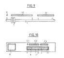
- FIG. 9 shows a control member usable for the operation of the device of FIG. 1, in the form of a cursor C or of the end of a lever that can be moved manually along a slot F provided in the table dashboard of an automobile.
- the stroke of the control member C extends between one end a and one end d passing through the intermediate points b and c, driving the lever 3 of FIG. 1 by any mechanical means.
- a symbol S1 opposite position a of the control member C indicates that this position corresponds to the stopping of the ventilation.
- An S2 symbol placed next to the ab portion of the stroke indicates that this corresponds to a cold air flow, and can also indicate that this cold air flow has an increasing flow from position a to position b .
- a third symbol S3 placed next to the por tion bd of the stroke of the control unit indicates that the temperature of the air stream sent to the aerators is increasing.
- control member C ⁇ is a wheel having a mark R which can move over a stroke ad, passing through intermediate positions b and c, when the wheel is rotated.
- positions of the reference frame R are affixed symbols S ⁇ 1, S ⁇ 2 and S ⁇ 3 having respectively the same meanings as the symbols S1, S2 and S3.
- an on / off button B is associated with a motor member such as a micromotor driving the cam 3 of FIG.
- control members of FIGS. 9 and 10 can also be used with the other control devices described, by associating therewith the symbols appropriate to each operating case.
Landscapes
- Physics & Mathematics (AREA)
- Thermal Sciences (AREA)
- Engineering & Computer Science (AREA)
- Mechanical Engineering (AREA)
- Air-Conditioning For Vehicles (AREA)
- Cooling, Air Intake And Gas Exhaust, And Fuel Tank Arrangements In Propulsion Units (AREA)
Applications Claiming Priority (2)
| Application Number | Priority Date | Filing Date | Title |
|---|---|---|---|
| FR8615284 | 1986-11-03 | ||
| FR8615284A FR2605942A1 (fr) | 1986-11-03 | 1986-11-03 | Dispositif pour la commande coordonnee de deux organes de reglage de debit de fluides |
Publications (1)
| Publication Number | Publication Date |
|---|---|
| EP0267101A1 true EP0267101A1 (de) | 1988-05-11 |
Family
ID=9340462
Family Applications (1)
| Application Number | Title | Priority Date | Filing Date |
|---|---|---|---|
| EP87402403A Withdrawn EP0267101A1 (de) | 1986-11-03 | 1987-10-26 | Vorrichtung zum koordinierten Steuern zweies Durchflussregelorgane für Strömungsmittel |
Country Status (2)
| Country | Link |
|---|---|
| EP (1) | EP0267101A1 (de) |
| FR (1) | FR2605942A1 (de) |
Cited By (12)
| Publication number | Priority date | Publication date | Assignee | Title |
|---|---|---|---|---|
| EP0330154A3 (de) * | 1988-02-22 | 1989-12-06 | BORLETTI CLIMATIZZAZIONE S.r.l. | Vorrichtung für die gleichzeitige oder getrennte Betätigung von Regelventilen in Kraftfahrzeug-Klimatisierungsanlagen |
| FR2643315A1 (fr) * | 1989-02-17 | 1990-08-24 | Valeo | Dispositif de commande a distance, notamment pour une installation de chauffage et/ou de climatisation |
| WO1990011904A1 (de) * | 1989-03-31 | 1990-10-18 | Siemens Aktiengesellschaft | Verfahren zur frischluftsteuerung in der mittelebene eines kraftfahrzeuges und einrichtung zur durchführung des verfahrens |
| FR2672016A1 (fr) * | 1991-01-30 | 1992-07-31 | Peugeot | Dispositif de climatisation de l'habitacle d'un vehicule automobile. |
| FR2701432A1 (fr) * | 1993-02-12 | 1994-08-19 | Behr Gmbh & Co | Installation de chauffage ou de climatisation, notamment pour véhicules automobiles, comportant deux volets répartissant des quantités d'air circulant dans un boîtier. |
| ES2112107A1 (es) * | 1993-04-06 | 1998-03-16 | Behr Gmbh & Co | Instalacion de calefaccion y/o climatizacion para automoviles. |
| FR2757596A1 (fr) * | 1996-12-20 | 1998-06-26 | Valeo Climatisation | Dispositif de transfert de mouvement, en particulier pour la commande d'un volet de distribution d'air |
| FR2757594A1 (fr) * | 1996-12-19 | 1998-06-26 | Valeo Climatisation | Dispositif de commande de volets d'entree d'air, notamment pour une installation de climatisation de vehicule automobile |
| US6484755B1 (en) | 1999-03-31 | 2002-11-26 | Valeo Climate Control Inc. | Blend door actuation for dual zone |
| ES2183655A1 (es) * | 1996-09-16 | 2003-03-16 | Valeo Climatizacion Sa | Dispositivo de control de palas de aparatos de calefaccion y/o climatizacion. |
| EP2774790A1 (de) * | 2013-03-09 | 2014-09-10 | Volkswagen Aktiengesellschaft | Klimatisierungsvorrichtung für ein Kraftfahrzeug und Steuerungsverfahren dafür |
| DE102013112631A1 (de) | 2013-11-15 | 2015-05-21 | Valeo Klimasysteme Gmbh | Steuervorrichtung zur Steuerung von wenigstens zwei Luftverteilerklappen einer Heiz- und/oder Klimaanlage eines Kraftfahrzeugs |
Citations (8)
| Publication number | Priority date | Publication date | Assignee | Title |
|---|---|---|---|---|
| DE1853104U (de) * | 1962-02-03 | 1962-06-07 | Sueddeutsche Kuehler Behr | Regelvorrichtung fuer kraftfahrzeug-heizungsanlagen. |
| FR2238105A1 (en) * | 1973-07-20 | 1975-02-14 | Ferodo Sa | Vehicle heating and ventilation air distributor - two spring loaded closure flaps are controlled by cam lever |
| FR2352336A1 (fr) * | 1976-05-21 | 1977-12-16 | Renault | Dispositif de manoeuvre a commandes multiples, notamment pour la climatisation des vehicules |
| FR2459511A1 (fr) * | 1979-06-20 | 1981-01-09 | Heuliez Sa Louis | Mecanisme de commande d'un dispositif de reglage, notamment ceux utilises sur un groupe de climatisation d'un vehicule automobile |
| FR2475468A1 (fr) * | 1980-02-08 | 1981-08-14 | Ferodo Sa | Equipement de commande d'une installation de chauffage et/ou de climatisation de vehicule automobile |
| FR2491839A1 (fr) * | 1980-10-10 | 1982-04-16 | Sueddeutsche Kuehler Behr | Mecanisme d'actionnement de registre |
| FR2494195A1 (fr) * | 1980-11-18 | 1982-05-21 | Heuliez Dea | Dispositif de commande d'un groupe de climatisation destine notamment aux vehicules automobiles |
| US4383642A (en) * | 1980-03-22 | 1983-05-17 | Diesel Kiki Co., Ltd. | Heater unit for use in an air conditioner for automotive vehicles |
-
1986
- 1986-11-03 FR FR8615284A patent/FR2605942A1/fr not_active Withdrawn
-
1987
- 1987-10-26 EP EP87402403A patent/EP0267101A1/de not_active Withdrawn
Patent Citations (8)
| Publication number | Priority date | Publication date | Assignee | Title |
|---|---|---|---|---|
| DE1853104U (de) * | 1962-02-03 | 1962-06-07 | Sueddeutsche Kuehler Behr | Regelvorrichtung fuer kraftfahrzeug-heizungsanlagen. |
| FR2238105A1 (en) * | 1973-07-20 | 1975-02-14 | Ferodo Sa | Vehicle heating and ventilation air distributor - two spring loaded closure flaps are controlled by cam lever |
| FR2352336A1 (fr) * | 1976-05-21 | 1977-12-16 | Renault | Dispositif de manoeuvre a commandes multiples, notamment pour la climatisation des vehicules |
| FR2459511A1 (fr) * | 1979-06-20 | 1981-01-09 | Heuliez Sa Louis | Mecanisme de commande d'un dispositif de reglage, notamment ceux utilises sur un groupe de climatisation d'un vehicule automobile |
| FR2475468A1 (fr) * | 1980-02-08 | 1981-08-14 | Ferodo Sa | Equipement de commande d'une installation de chauffage et/ou de climatisation de vehicule automobile |
| US4383642A (en) * | 1980-03-22 | 1983-05-17 | Diesel Kiki Co., Ltd. | Heater unit for use in an air conditioner for automotive vehicles |
| FR2491839A1 (fr) * | 1980-10-10 | 1982-04-16 | Sueddeutsche Kuehler Behr | Mecanisme d'actionnement de registre |
| FR2494195A1 (fr) * | 1980-11-18 | 1982-05-21 | Heuliez Dea | Dispositif de commande d'un groupe de climatisation destine notamment aux vehicules automobiles |
Cited By (16)
| Publication number | Priority date | Publication date | Assignee | Title |
|---|---|---|---|---|
| EP0330154A3 (de) * | 1988-02-22 | 1989-12-06 | BORLETTI CLIMATIZZAZIONE S.r.l. | Vorrichtung für die gleichzeitige oder getrennte Betätigung von Regelventilen in Kraftfahrzeug-Klimatisierungsanlagen |
| FR2643315A1 (fr) * | 1989-02-17 | 1990-08-24 | Valeo | Dispositif de commande a distance, notamment pour une installation de chauffage et/ou de climatisation |
| WO1990011904A1 (de) * | 1989-03-31 | 1990-10-18 | Siemens Aktiengesellschaft | Verfahren zur frischluftsteuerung in der mittelebene eines kraftfahrzeuges und einrichtung zur durchführung des verfahrens |
| US5338249A (en) * | 1989-03-31 | 1994-08-16 | Siemens Aktiengesellschaft | Method and apparatus for fresh-air control in the mid-level area of a motor vehicle |
| FR2672016A1 (fr) * | 1991-01-30 | 1992-07-31 | Peugeot | Dispositif de climatisation de l'habitacle d'un vehicule automobile. |
| EP0497639A1 (de) * | 1991-01-30 | 1992-08-05 | Automobiles Peugeot | Klimaanlage für Kraftfahrzeuginnenraum |
| FR2701432A1 (fr) * | 1993-02-12 | 1994-08-19 | Behr Gmbh & Co | Installation de chauffage ou de climatisation, notamment pour véhicules automobiles, comportant deux volets répartissant des quantités d'air circulant dans un boîtier. |
| ES2112107A1 (es) * | 1993-04-06 | 1998-03-16 | Behr Gmbh & Co | Instalacion de calefaccion y/o climatizacion para automoviles. |
| ES2183655A1 (es) * | 1996-09-16 | 2003-03-16 | Valeo Climatizacion Sa | Dispositivo de control de palas de aparatos de calefaccion y/o climatizacion. |
| FR2757594A1 (fr) * | 1996-12-19 | 1998-06-26 | Valeo Climatisation | Dispositif de commande de volets d'entree d'air, notamment pour une installation de climatisation de vehicule automobile |
| FR2757596A1 (fr) * | 1996-12-20 | 1998-06-26 | Valeo Climatisation | Dispositif de transfert de mouvement, en particulier pour la commande d'un volet de distribution d'air |
| US6484755B1 (en) | 1999-03-31 | 2002-11-26 | Valeo Climate Control Inc. | Blend door actuation for dual zone |
| US6789607B1 (en) | 1999-03-31 | 2004-09-14 | Valeo Climate Control Corp. | Dual zone vehicle air distribution apparatus |
| EP2774790A1 (de) * | 2013-03-09 | 2014-09-10 | Volkswagen Aktiengesellschaft | Klimatisierungsvorrichtung für ein Kraftfahrzeug und Steuerungsverfahren dafür |
| DE102013112631A1 (de) | 2013-11-15 | 2015-05-21 | Valeo Klimasysteme Gmbh | Steuervorrichtung zur Steuerung von wenigstens zwei Luftverteilerklappen einer Heiz- und/oder Klimaanlage eines Kraftfahrzeugs |
| WO2015071340A1 (en) | 2013-11-15 | 2015-05-21 | Valeo Klimasysteme Gmbh | Control device for controlling at least two air distribution flaps of a heating and/or air-conditioning unit of a motor vehicle |
Also Published As
| Publication number | Publication date |
|---|---|
| FR2605942A1 (fr) | 1988-05-06 |
Similar Documents
| Publication | Publication Date | Title |
|---|---|---|
| EP0267101A1 (de) | Vorrichtung zum koordinierten Steuern zweies Durchflussregelorgane für Strömungsmittel | |
| EP0942156B1 (de) | Abgaswärmetauschervorrichtung | |
| EP2010774B1 (de) | Durch einen gemeinsamen motor angetriebenes doppelklappenventil | |
| EP1013490A1 (de) | Fahrzeugklimaanlage mit verbesserter Luftmischung | |
| EP0500430A1 (de) | Drehklappeneinrichtung zur Regelung des Luftstromes durch einen Wärmetauscher | |
| EP3887182B1 (de) | Dünne belüftung mit coanda-effekt für ein kraftfahrzeug | |
| FR2491839A1 (fr) | Mecanisme d'actionnement de registre | |
| EP0497639B1 (de) | Klimaanlage für Kraftfahrzeuginnenraum | |
| EP0246948B1 (de) | Heiz- und Belüftungseinrichtung für ein Kraftfahrzeug | |
| EP2986877B1 (de) | Ventil, insbesondere motorsteuerventil, mit einem dosierschieber und einem ablenkschieber | |
| EP0568444B1 (de) | Belüftungsvorrichtung für den Innenraum eines Kraftfahrzeuges | |
| FR2752775A1 (fr) | Dispositif de commande d'un volet pour une installation de chauffage et/ou climatisation de vehicule automobile | |
| FR2506905A1 (fr) | Vanne melangeuse a trois ou quatre voies | |
| FR2672859A1 (fr) | Installation d'essuie-glace pour vehicule automobile. | |
| FR2619857A1 (fr) | Groupe a moteur a combustion interne | |
| FR2703631A1 (fr) | Système de chauffage ou de climatisation pour véhicules automobiles. | |
| FR2862255A1 (fr) | Dispositif de chauffage, ventilation et conditionnement d'air de vehicules | |
| FR2507252A1 (fr) | Eolienne a turbine | |
| EP0477047B1 (de) | Temperaturregelungsvorrichtung einer Klimaanlage, z.B. für ein Kraftfahrzeug | |
| FR3081778A1 (fr) | Dispositif d'aeration comprenant un volet pilote par un element de commande et un dispositif de transmission | |
| FR2511522A1 (fr) | Dispositif de commande de deux elements rotatifs tels que des volets, et installation de chauffage ou de climatisation pour vehicule automobile comprenant un tel dispositif | |
| EP0945599A1 (de) | Absperrklappe für eine Leitung und Brennkraftmaschine mit einer solchen Vorrichtung | |
| FR2756901A1 (fr) | Dispositif de commande d'un volet de reglage d'air pour une installation de chauffage-ventilation et/ou climatisation de vehicule automobile | |
| FR2701432A1 (fr) | Installation de chauffage ou de climatisation, notamment pour véhicules automobiles, comportant deux volets répartissant des quantités d'air circulant dans un boîtier. | |
| JPH0227199B2 (de) |
Legal Events
| Date | Code | Title | Description |
|---|---|---|---|
| PUAI | Public reference made under article 153(3) epc to a published international application that has entered the european phase |
Free format text: ORIGINAL CODE: 0009012 |
|
| AK | Designated contracting states |
Kind code of ref document: A1 Designated state(s): DE IT |
|
| 17P | Request for examination filed |
Effective date: 19880418 |
|
| STAA | Information on the status of an ep patent application or granted ep patent |
Free format text: STATUS: THE APPLICATION IS DEEMED TO BE WITHDRAWN |
|
| 18D | Application deemed to be withdrawn |
Effective date: 19900501 |
|
| RIN1 | Information on inventor provided before grant (corrected) |
Inventor name: VINCENT, PHILIPPE |