EP0267140A2 - Compensateur pour trépan de forage du sol - Google Patents
Compensateur pour trépan de forage du sol Download PDFInfo
- Publication number
- EP0267140A2 EP0267140A2 EP87630222A EP87630222A EP0267140A2 EP 0267140 A2 EP0267140 A2 EP 0267140A2 EP 87630222 A EP87630222 A EP 87630222A EP 87630222 A EP87630222 A EP 87630222A EP 0267140 A2 EP0267140 A2 EP 0267140A2
- Authority
- EP
- European Patent Office
- Prior art keywords
- lubricant
- mud
- diaphragm
- pressure
- region
- Prior art date
- Legal status (The legal status is an assumption and is not a legal conclusion. Google has not performed a legal analysis and makes no representation as to the accuracy of the status listed.)
- Granted
Links
Images



Classifications
-
- F—MECHANICAL ENGINEERING; LIGHTING; HEATING; WEAPONS; BLASTING
- F16—ENGINEERING ELEMENTS AND UNITS; GENERAL MEASURES FOR PRODUCING AND MAINTAINING EFFECTIVE FUNCTIONING OF MACHINES OR INSTALLATIONS; THERMAL INSULATION IN GENERAL
- F16N—LUBRICATING
- F16N7/00—Arrangements for supplying oil or unspecified lubricant from a stationary reservoir or the equivalent in or on the machine or member to be lubricated
- F16N7/30—Arrangements for supplying oil or unspecified lubricant from a stationary reservoir or the equivalent in or on the machine or member to be lubricated the oil being fed or carried along by another fluid
-
- E—FIXED CONSTRUCTIONS
- E21—EARTH OR ROCK DRILLING; MINING
- E21B—EARTH OR ROCK DRILLING; OBTAINING OIL, GAS, WATER, SOLUBLE OR MELTABLE MATERIALS OR A SLURRY OF MINERALS FROM WELLS
- E21B10/00—Drill bits
- E21B10/08—Roller bits
- E21B10/22—Roller bits characterised by bearing, lubrication or sealing details
- E21B10/24—Roller bits characterised by bearing, lubrication or sealing details characterised by lubricating details
Definitions
- This invention relates in general to earth boring bits but in particular to improvements in their lubricant pressure compensators and relief means.
- Earth boring bits of the rolling cutter type have sealed bearings and lubrication systems that include pressure compensation and relief means to minimize the pressure differential across the seals that separate the lubricant from the drilling mud in a bore hole.
- a successful seal means is disclosed by Edward M. Galle in U.S. Patent No. 3,397,928.
- a successful pressure compensation and relief means is disclosed by Stuart C. Millsapps, Jr., in U.S. Patent No. 4,055,225.
- Other systems include the use of the original commercially successful pressure relief valve disclosed by Galle in U.S. Patent No. 3,476,195 and the use of a pinhole or slit in a flexible compensator or diaphragm that permits liquid flow either into or from the compensator cavity, as disclosed by Schumacher in U.S. Patent No. 3,847,234.
- the improved compensator has a flexible diaphragm in a compensator cavity that minimizes tensile stresses in the diaphragm.
- Metal components are not used in the diaphragm to avoid the failures that occur in the bonded region between metal and rubber.
- the flexible diaphragm has a perforated protrusion extending into the drilling mud region.
- the perforation is self energizing and seals when the pressure of the lubricant is less than or substantially equal to that of the mud that surrounds the bit during drilling.
- a wall at the end of a compensator cavity in the bit body contains a mud passage and engages an area of the compensator around the protrusion when the diaphragm is fully extended by lubricant pressure build-up that exceeds the hydrostatic pressure of the mud. This minimizes tensile stresses in the diaphragm.
- the resulting pressure differential opens the perforation, releases lubricant and relieves the build-up of lubricant pressure.
- the exterior or mud side of the protrusion is cylindrical and a beveled entrance to the perforation is used on the lubricant side of the diaphragm.
- the protrusion ideally has an annular reinforcing ridge to confine the ends of the perforation, which is usually a slit.
- the diaphragm has a periphery enlarged to accommodate an integral o-ring that is compressed between captive, preferably beveled surfaces on a compensator protector cup and the compensator cavity.
- the end of the diaphragm has clearance from the end of the compensator cavity and clearance from the end of the protector cup when fully extended but unstressed. This centers the protrusion when fully extended in either direction.
- the numeral 11 in the drawing designates an earth boring bit which consists of three identical head sections 13, each of which supports a rotatable cutter 15 having a plurality of earth disintegrating teeth 17, here depicted as being inserts of sintered tungsten carbide.
- the three head sections 13 together form a head or body having a hollow interior 19 which terminates at the lower end in usually three passages, each containing a nozzle 21 used to direct drilling fluid or mud against the borehole bottom (not shown).
- a lubricant passage 23 in each head section extends between the bearing means 25 of a cantilevered bearing shaft 26 and a lubricant pressure compensator and relief means 27.
- Lubricant is maintained in the bearing means 25 by a seal means 29, here an o-ring as shown in the previously mentioned Galle U.S. Patent 3,397,928.
- Each rotatable cutter 15 is retained to the bearing shaft 26 by suitable means such as the snap ring, as disclosed by Burr, et al in U.S. Patent No. 4,491,428.
- a lubricant compensator and relief means 27 is positioned or formed in each of the head sections 13.
- a mud passage 41 leads to an interior body or wall surface 39 (see Fig. 1) on the interior of the bit above the rotatable cutters 15.
- An interior wall or shoulder 43 forms the lower part of a compensator cavity 45 which has a lower region 47 of one diameter and an upper region 49 of a larger diameter.
- a recess 51 contains an o-ring 52 in a groove or gland 53 and includes a snap ring 54 in a recess 55 is used to retain a compensator cap 77.
- the lower region 47 of the compensator cavity 45 as shown in Fig. 2 contains a flexible diaphragm 57 that has a central portion 59 perforated at 61 and beveled at 62.
- the perforation 61 is actually a slit starting in a recess 64 having ends limited by an annular ridge 66.
- the periphery 63 of the diaphragm 57 is in the form of an o-ring shaped annular area that is compressed between an inverted incline or lip 65 in the cavity upper region 49 and an opposed downwardly facing beveled portion or shoulder 67 on the lower extremity of a protector cup 69.
- This cup has an aperture 71 in its upper portion 73, through which grease communicates with the lubricant passage 23.
- the protector cup 69 is biased downwardly by a lower surface 75 in a compensator cap 77, which has a passage 79 through which lubricant is forced prior to insertion of a pressure seal pipe plug 81.
- An arcuate groove 83 permits lubricant flow freely between the passage 23 in the head section 13, around the exterior surface 85 of the protector cup 69, and to or from the interior volume 87 (defined by the interior surfaces 89 of the protector cup 69 and an interior surface 91 of the flexible diaphragm 57).
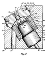
- the flexible diaphragm 57 Upon assembly and in operation, the flexible diaphragm 57 has its periphery 63 compressed (indicated by the dotted lines) and is sealingly secured in the compensator cavity between surfaces 65, 67 to form a mud region 93 and a lubricant volume or region 87.
- the central portion 59 of the flexible diaphragm 57 has a perforation 61 and extends into passage 41 of mud region 93 when fully expanded to form a self energizing area, exposed to the drilling mud, that seals the perforation when the pressure of the lubricant is less than or substantially equal to that of the mud.
- the resulting pressure differential opens the perforation 61, releases the lubricant and relieves the build-up of lubricant pressure inside the lubricant volume 87.
- the diaphragm is preferably constructed of nitrile rubber and the perforation is sized along with the configuration of central portion 59, such that it will open at a selected pressure not less than substantially fifty psi.
- This self energizing effect is achieved in the preferred embodiment by utilizing a protrusion having an area exposed to the mud that is greater than the area exposed to the lubricant such that sealing of the perforation is effected for all mud pressures greater than the lubricant pressure.
- the protrusion is cylindrical, with a radius joining the exterior surface of the flexible diaphragm 57, as indicated in Figure 2.
- the width of perforation or slit 61 is determined by the diameter of the annular ridge 66. Its length or depth is determined by the thickness of the diaphragm, the depth of bevel 62 and the height of central portion or appendage 59. All of these features determine the differential pressure at which the slit 61 is energized to release lubricant.
- Another feature of the invention are the clearances D1 (see Fig. 2) and D2 (see Fig. 3). These clearances occur when the flexible diaphragm is completely filled with lubricant (Fig.2) or inverted by drilling mud (Fig. 3), but before the rubber is stretched. This self-centers the central portion or appendage 59 with respect to mud passage 41 (Fig. 2) and aperture 71 (Fig. 3). Otherwise, a relatively thin wall section of the diaphragm may align with either mud passage 41 or aperture 71 and a large pressure differential may rupture the diaphragm.
- the flexible diaphragm 57 is connected without bonding to the compensator cavity 45 by the compression of its periphery 63 between the surface 65 and the beveled portion 67 of the protector cup. Separation and failure of diaphragms or compensators have been observed when metal/rubber bonding is used. Such constructions may cause excessive stress in the rubber at the bonded areas during pressure build-up in the lubricant. Further, the use of a shoulder 43 in the compensator cavity 45 to engage the end of the perforated diaphragm minimizes stresses and enhances reliability.
- protector cup 69 is designed to form a backup support for the central portion 59 of flexible diaphragm 57 so that when substantially higher mud pressure than lubricant pressure exists no damage will occur to the diaphragm.
Landscapes
- Engineering & Computer Science (AREA)
- Geology (AREA)
- Mechanical Engineering (AREA)
- Life Sciences & Earth Sciences (AREA)
- General Engineering & Computer Science (AREA)
- Mining & Mineral Resources (AREA)
- General Life Sciences & Earth Sciences (AREA)
- Fluid Mechanics (AREA)
- Physics & Mathematics (AREA)
- Geochemistry & Mineralogy (AREA)
- Chemical & Material Sciences (AREA)
- Combustion & Propulsion (AREA)
- Oil, Petroleum & Natural Gas (AREA)
- Environmental & Geological Engineering (AREA)
- Earth Drilling (AREA)
Applications Claiming Priority (2)
| Application Number | Priority Date | Filing Date | Title |
|---|---|---|---|
| US927789 | 1986-11-05 | ||
| US06/927,789 US4727942A (en) | 1986-11-05 | 1986-11-05 | Compensator for earth boring bits |
Publications (3)
| Publication Number | Publication Date |
|---|---|
| EP0267140A2 true EP0267140A2 (fr) | 1988-05-11 |
| EP0267140A3 EP0267140A3 (en) | 1989-05-31 |
| EP0267140B1 EP0267140B1 (fr) | 1993-03-31 |
Family
ID=25455257
Family Applications (1)
| Application Number | Title | Priority Date | Filing Date |
|---|---|---|---|
| EP87630222A Expired - Lifetime EP0267140B1 (fr) | 1986-11-05 | 1987-11-03 | Compensateur pour trépan de forage du sol |
Country Status (7)
| Country | Link |
|---|---|
| US (1) | US4727942A (fr) |
| EP (1) | EP0267140B1 (fr) |
| JP (1) | JPS63138094A (fr) |
| BR (1) | BR8705920A (fr) |
| CA (1) | CA1288763C (fr) |
| DE (1) | DE3785150T2 (fr) |
| MX (1) | MX160892A (fr) |
Cited By (4)
| Publication number | Priority date | Publication date | Assignee | Title |
|---|---|---|---|---|
| GB2365038A (en) * | 2000-07-27 | 2002-02-13 | Walker & Co James Ltd | Pressure relief seal for a drill bit |
| GB2387192A (en) * | 2002-04-03 | 2003-10-08 | Smith International | Self relieving seal |
| RU2230876C2 (ru) * | 2002-09-03 | 2004-06-20 | Открытое акционерное общество "Волгабурмаш" | Буровое долото с усиленной армировкой спинок лап |
| US9784073B2 (en) | 2004-11-23 | 2017-10-10 | Weatherford Technology Holdings, Llc | Rotating control device docking station |
Families Citing this family (61)
| Publication number | Priority date | Publication date | Assignee | Title |
|---|---|---|---|---|
| US5072795A (en) * | 1991-01-22 | 1991-12-17 | Camco International Inc. | Pressure compensator for drill bit lubrication system |
| US5129471A (en) * | 1991-05-31 | 1992-07-14 | Hughes Tool Company | Earth boring bit with protected seal means |
| US5558172A (en) * | 1994-12-01 | 1996-09-24 | Briscoe Tool Company | Earth boring bit and lubricator compensation therefor |
| US5520257A (en) * | 1994-12-05 | 1996-05-28 | Baker Hughes Incorporated | Bit with ball plug compensator having pressure relief means |
| US5655611A (en) * | 1995-08-04 | 1997-08-12 | Baker Hughes Inc. | Earth-boring bit with improved bearing seal |
| US6092611A (en) * | 1997-05-28 | 2000-07-25 | Dresser Industries, Inc. | Encapsulated elastomeric relief valve |
| US6213228B1 (en) | 1997-08-08 | 2001-04-10 | Dresser Industries Inc. | Roller cone drill bit with improved pressure compensation |
| US6026917A (en) | 1997-12-18 | 2000-02-22 | Baker Hughes Incorporated | Earth-boring bit with improved bearing seal |
| US6913092B2 (en) * | 1998-03-02 | 2005-07-05 | Weatherford/Lamb, Inc. | Method and system for return of drilling fluid from a sealed marine riser to a floating drilling rig while drilling |
| DE19814214A1 (de) * | 1998-03-31 | 1999-10-07 | Flender A F & Co | Maschinenelement mit Hydraulikfüllung, insbesondere Lager oder Welle |
| US6253862B1 (en) * | 1999-02-03 | 2001-07-03 | Baker Hughes Incorporated | Earth-boring bit with cutter spear point hardfacing |
| US7159669B2 (en) | 1999-03-02 | 2007-01-09 | Weatherford/Lamb, Inc. | Internal riser rotating control head |
| US6202766B1 (en) | 1999-03-24 | 2001-03-20 | William L. Shepherd | Relief valve |
| US6138778A (en) * | 1999-08-20 | 2000-10-31 | Camco International Inc. | Rock bit lubricant relief valve |
| US7036611B2 (en) * | 2002-07-30 | 2006-05-02 | Baker Hughes Incorporated | Expandable reamer apparatus for enlarging boreholes while drilling and methods of use |
| US7487837B2 (en) * | 2004-11-23 | 2009-02-10 | Weatherford/Lamb, Inc. | Riser rotating control device |
| US7836946B2 (en) * | 2002-10-31 | 2010-11-23 | Weatherford/Lamb, Inc. | Rotating control head radial seal protection and leak detection systems |
| US7237623B2 (en) | 2003-09-19 | 2007-07-03 | Weatherford/Lamb, Inc. | Method for pressurized mud cap and reverse circulation drilling from a floating drilling rig using a sealed marine riser |
| US8826988B2 (en) | 2004-11-23 | 2014-09-09 | Weatherford/Lamb, Inc. | Latch position indicator system and method |
| US7241049B2 (en) | 2004-12-03 | 2007-07-10 | Baker Hughes Incorporated | Micropore engagement surfaces for earth boring bit |
| US7841426B2 (en) * | 2007-04-05 | 2010-11-30 | Baker Hughes Incorporated | Hybrid drill bit with fixed cutters as the sole cutting elements in the axial center of the drill bit |
| US20100025119A1 (en) * | 2007-04-05 | 2010-02-04 | Baker Hughes Incorporated | Hybrid drill bit and method of using tsp or mosaic cutters on a hybrid bit |
| US7845435B2 (en) * | 2007-04-05 | 2010-12-07 | Baker Hughes Incorporated | Hybrid drill bit and method of drilling |
| US7997345B2 (en) * | 2007-10-19 | 2011-08-16 | Weatherford/Lamb, Inc. | Universal marine diverter converter |
| US8844652B2 (en) | 2007-10-23 | 2014-09-30 | Weatherford/Lamb, Inc. | Interlocking low profile rotating control device |
| US8286734B2 (en) | 2007-10-23 | 2012-10-16 | Weatherford/Lamb, Inc. | Low profile rotating control device |
| US8678111B2 (en) * | 2007-11-16 | 2014-03-25 | Baker Hughes Incorporated | Hybrid drill bit and design method |
| US7735583B2 (en) * | 2007-11-21 | 2010-06-15 | Baker Hughes Incorporated | Roller cone bit bearing with elastomeric seal having self break-in property and method |
| US20090272582A1 (en) * | 2008-05-02 | 2009-11-05 | Baker Hughes Incorporated | Modular hybrid drill bit |
| US7819208B2 (en) * | 2008-07-25 | 2010-10-26 | Baker Hughes Incorporated | Dynamically stable hybrid drill bit |
| US8450637B2 (en) * | 2008-10-23 | 2013-05-28 | Baker Hughes Incorporated | Apparatus for automated application of hardfacing material to drill bits |
| US9439277B2 (en) * | 2008-10-23 | 2016-09-06 | Baker Hughes Incorporated | Robotically applied hardfacing with pre-heat |
| WO2010053710A2 (fr) * | 2008-10-29 | 2010-05-14 | Baker Hughes Incorporated | Procédé et appareil pour soudage robotique de trépans |
| US8047307B2 (en) * | 2008-12-19 | 2011-11-01 | Baker Hughes Incorporated | Hybrid drill bit with secondary backup cutters positioned with high side rake angles |
| US20100155146A1 (en) * | 2008-12-19 | 2010-06-24 | Baker Hughes Incorporated | Hybrid drill bit with high pilot-to-journal diameter ratio |
| MX2011006187A (es) * | 2008-12-31 | 2011-06-20 | Baker Hughes Inc | Metodo y aparato para la aplicacion automatizada de material de revestimiento duro a fresas envolventes de barrenas de perforacion terrestre tipo hibridas, barrenas de perforacion hibridas que comprenden tales elementos de corte de dientes de acero c |
| US8322432B2 (en) | 2009-01-15 | 2012-12-04 | Weatherford/Lamb, Inc. | Subsea internal riser rotating control device system and method |
| US9359853B2 (en) | 2009-01-15 | 2016-06-07 | Weatherford Technology Holdings, Llc | Acoustically controlled subsea latching and sealing system and method for an oilfield device |
| US20100181116A1 (en) * | 2009-01-16 | 2010-07-22 | Baker Hughes Incororated | Impregnated drill bit with diamond pins |
| US8141664B2 (en) | 2009-03-03 | 2012-03-27 | Baker Hughes Incorporated | Hybrid drill bit with high bearing pin angles |
| US8056651B2 (en) * | 2009-04-28 | 2011-11-15 | Baker Hughes Incorporated | Adaptive control concept for hybrid PDC/roller cone bits |
| US8459378B2 (en) * | 2009-05-13 | 2013-06-11 | Baker Hughes Incorporated | Hybrid drill bit |
| US8157026B2 (en) | 2009-06-18 | 2012-04-17 | Baker Hughes Incorporated | Hybrid bit with variable exposure |
| US8347983B2 (en) * | 2009-07-31 | 2013-01-08 | Weatherford/Lamb, Inc. | Drilling with a high pressure rotating control device |
| WO2011017642A2 (fr) * | 2009-08-07 | 2011-02-10 | Baker Hughes Incorporated | Pointes en étoile anti-retombées pour trépans de forage |
| EP2478177A2 (fr) | 2009-09-16 | 2012-07-25 | Baker Hughes Incorporated | Ensembles de palier en carbone de diamant polycristallin divorcés externes pour trépans de forage hybrides |
| US8347989B2 (en) * | 2009-10-06 | 2013-01-08 | Baker Hughes Incorporated | Hole opener with hybrid reaming section and method of making |
| US8448724B2 (en) * | 2009-10-06 | 2013-05-28 | Baker Hughes Incorporated | Hole opener with hybrid reaming section |
| US8347982B2 (en) | 2010-04-16 | 2013-01-08 | Weatherford/Lamb, Inc. | System and method for managing heave pressure from a floating rig |
| US9175542B2 (en) | 2010-06-28 | 2015-11-03 | Weatherford/Lamb, Inc. | Lubricating seal for use with a tubular |
| CN108049818B (zh) | 2010-06-29 | 2020-11-17 | 贝克休斯公司 | 具有防钻头循旧槽结构的钻头 |
| US8978786B2 (en) | 2010-11-04 | 2015-03-17 | Baker Hughes Incorporated | System and method for adjusting roller cone profile on hybrid bit |
| EP2673451B1 (fr) | 2011-02-11 | 2015-05-27 | Baker Hughes Incorporated | Système et procédé pour retenue de patte sur trépans hybrides |
| US9782857B2 (en) | 2011-02-11 | 2017-10-10 | Baker Hughes Incorporated | Hybrid drill bit having increased service life |
| EP3159475B1 (fr) | 2011-11-15 | 2019-03-27 | Baker Hughes, a GE company, LLC | Trépans hybrides ayant une meilleure efficacité de forage |
| US9803427B1 (en) | 2014-03-27 | 2017-10-31 | U.S. Synthetic Corporation | Systems and methods for mounting a cutter in a drill bit |
| US10107039B2 (en) | 2014-05-23 | 2018-10-23 | Baker Hughes Incorporated | Hybrid bit with mechanically attached roller cone elements |
| US11428050B2 (en) | 2014-10-20 | 2022-08-30 | Baker Hughes Holdings Llc | Reverse circulation hybrid bit |
| CN107709693A (zh) | 2015-07-17 | 2018-02-16 | 哈里伯顿能源服务公司 | 中心具有反向旋转切削器的混合钻头 |
| US10260289B1 (en) | 2018-01-18 | 2019-04-16 | William L. Shepherd | Drilling system with drill bit for mining machine |
| CN113477990B (zh) * | 2021-07-16 | 2022-04-08 | 穆格精密工具(杭州)有限公司 | 一种套料刀自动推料机构 |
Family Cites Families (14)
| Publication number | Priority date | Publication date | Assignee | Title |
|---|---|---|---|---|
| US2342355A (en) * | 1938-09-13 | 1944-02-22 | Mercier Jean | Deformable or elastic accumulator |
| US2724442A (en) * | 1952-08-20 | 1955-11-22 | Leslie A Layne | Full opening valve with elastic, self sealing closure means |
| US3007751A (en) * | 1958-06-16 | 1961-11-07 | Hughes Tool Co | Lubricator |
| US3370659A (en) * | 1964-09-25 | 1968-02-27 | Gatien Paul Germain | Drill rod and bit including one-way valve structure therein |
| US3476195A (en) * | 1968-11-15 | 1969-11-04 | Hughes Tool Co | Lubricant relief valve for rock bits |
| US3719241A (en) * | 1971-11-24 | 1973-03-06 | Dresser Ind | Free breathing lubrication system for sealed bearing rock bits |
| US3847234A (en) * | 1972-06-01 | 1974-11-12 | Reed Tool Co | Pressure relief device for drill bit lubrication system |
| US3844364A (en) * | 1973-10-23 | 1974-10-29 | Dresser Ind | Hydrostatic rock bit lubrication system |
| US3935911A (en) * | 1974-06-28 | 1976-02-03 | Dresser Industries, Inc. | Earth boring bit with means for conducting heat from the bit's bearings |
| US3995367A (en) * | 1976-03-01 | 1976-12-07 | Dresser Industries, Inc. | Bearing separator and sealing system for rock bit |
| US4055225A (en) * | 1976-05-17 | 1977-10-25 | Hughes Tool Company | Lubricant pressure compensator for an earth boring drill bit |
| US4073548A (en) * | 1976-11-01 | 1978-02-14 | Dresser Industries, Inc. | Sealing system for a rotary rock bit |
| US4168868A (en) * | 1978-07-17 | 1979-09-25 | Dresser Industries, Inc. | Sealing system for an earth boring cutter |
| JPS5825036Y2 (ja) * | 1981-05-29 | 1983-05-28 | 塚本精機株式会社 | 回転掘削工具の圧力補償装置 |
-
1986
- 1986-11-05 US US06/927,789 patent/US4727942A/en not_active Expired - Lifetime
-
1987
- 1987-07-16 CA CA000542274A patent/CA1288763C/fr not_active Expired - Lifetime
- 1987-11-03 EP EP87630222A patent/EP0267140B1/fr not_active Expired - Lifetime
- 1987-11-03 DE DE8787630222T patent/DE3785150T2/de not_active Expired - Fee Related
- 1987-11-04 BR BR8705920A patent/BR8705920A/pt not_active IP Right Cessation
- 1987-11-05 MX MX9152A patent/MX160892A/es unknown
- 1987-11-05 JP JP62280282A patent/JPS63138094A/ja active Granted
Cited By (9)
| Publication number | Priority date | Publication date | Assignee | Title |
|---|---|---|---|---|
| GB2365038A (en) * | 2000-07-27 | 2002-02-13 | Walker & Co James Ltd | Pressure relief seal for a drill bit |
| GB2365038B (en) * | 2000-07-27 | 2004-06-02 | Walker & Co James Ltd | Sealing structure for a rock drill bit |
| GB2387192A (en) * | 2002-04-03 | 2003-10-08 | Smith International | Self relieving seal |
| GB2387192B (en) * | 2002-04-03 | 2005-11-23 | Smith International | Self relieving seal |
| US6976548B2 (en) | 2002-04-03 | 2005-12-20 | Smith International, Inc. | Self relieving seal |
| US7201241B2 (en) | 2002-04-03 | 2007-04-10 | Smith International, Inc. | Self relieving seal |
| US7387178B2 (en) | 2002-04-03 | 2008-06-17 | Smith International, Inc. | Self relieving seal |
| RU2230876C2 (ru) * | 2002-09-03 | 2004-06-20 | Открытое акционерное общество "Волгабурмаш" | Буровое долото с усиленной армировкой спинок лап |
| US9784073B2 (en) | 2004-11-23 | 2017-10-10 | Weatherford Technology Holdings, Llc | Rotating control device docking station |
Also Published As
| Publication number | Publication date |
|---|---|
| DE3785150D1 (de) | 1993-05-06 |
| CA1288763C (fr) | 1991-09-10 |
| EP0267140A3 (en) | 1989-05-31 |
| MX160892A (es) | 1990-06-11 |
| EP0267140B1 (fr) | 1993-03-31 |
| JPH0411715B2 (fr) | 1992-03-02 |
| BR8705920A (pt) | 1988-06-14 |
| JPS63138094A (ja) | 1988-06-10 |
| DE3785150T2 (de) | 1993-07-15 |
| US4727942A (en) | 1988-03-01 |
Similar Documents
| Publication | Publication Date | Title |
|---|---|---|
| US4727942A (en) | Compensator for earth boring bits | |
| EP1409836B1 (fr) | Trepan a molette a joint metallique | |
| US6142249A (en) | Earth-boring bit with improved bearing seal | |
| US5513711A (en) | Sealed and lubricated rotary cone drill bit having improved seal protection | |
| US4055225A (en) | Lubricant pressure compensator for an earth boring drill bit | |
| US4176848A (en) | Rotary bearing seal for drill bits | |
| US3303898A (en) | Bearing sealing and lubricating device | |
| US3719241A (en) | Free breathing lubrication system for sealed bearing rock bits | |
| US4073548A (en) | Sealing system for a rotary rock bit | |
| CA2102984C (fr) | Roulement etanche pour machine de forage de terrain | |
| JPS6361471B2 (fr) | ||
| CN1268992A (zh) | 具有润滑液压力补偿装置的牙轮钻头 | |
| JPS6361472B2 (fr) | ||
| US4168868A (en) | Sealing system for an earth boring cutter | |
| US4252330A (en) | Symmetrical seal for a rolling cone cutter earth boring bit | |
| US4277109A (en) | Axial compression positive rock bit seal | |
| US10947804B2 (en) | Metal-to-metal annulus wellhead style seal with pressure energized from above and below | |
| US4577705A (en) | Bellows lubricant pressurizer for sealed bearing rock bits | |
| US4209890A (en) | Method of making a rotary rock bit with seal recess washer | |
| US3735825A (en) | Pressure equalizing system for rock bits | |
| US4274498A (en) | Rock bit lubrication system utilizing expellable plug for obtaining expansion space | |
| US4552228A (en) | Low pressure differential compensator | |
| US4262759A (en) | Combination seal and pressure relief valve for sealed drill string unit | |
| US4279450A (en) | Rotary rock bit fluid center seal | |
| US5520257A (en) | Bit with ball plug compensator having pressure relief means |
Legal Events
| Date | Code | Title | Description |
|---|---|---|---|
| PUAI | Public reference made under article 153(3) epc to a published international application that has entered the european phase |
Free format text: ORIGINAL CODE: 0009012 |
|
| AK | Designated contracting states |
Kind code of ref document: A2 Designated state(s): DE FR GB IT |
|
| PUAL | Search report despatched |
Free format text: ORIGINAL CODE: 0009013 |
|
| RAP1 | Party data changed (applicant data changed or rights of an application transferred) |
Owner name: HUGHES TOOL COMPANY |
|
| AK | Designated contracting states |
Kind code of ref document: A3 Designated state(s): DE FR GB IT |
|
| 17P | Request for examination filed |
Effective date: 19890908 |
|
| 17Q | First examination report despatched |
Effective date: 19910118 |
|
| GRAA | (expected) grant |
Free format text: ORIGINAL CODE: 0009210 |
|
| AK | Designated contracting states |
Kind code of ref document: B1 Designated state(s): DE FR GB IT |
|
| ET | Fr: translation filed | ||
| REF | Corresponds to: |
Ref document number: 3785150 Country of ref document: DE Date of ref document: 19930506 |
|
| ITF | It: translation for a ep patent filed | ||
| PGFP | Annual fee paid to national office [announced via postgrant information from national office to epo] |
Ref country code: FR Payment date: 19931011 Year of fee payment: 7 |
|
| PGFP | Annual fee paid to national office [announced via postgrant information from national office to epo] |
Ref country code: DE Payment date: 19931022 Year of fee payment: 7 |
|
| PLBE | No opposition filed within time limit |
Free format text: ORIGINAL CODE: 0009261 |
|
| STAA | Information on the status of an ep patent application or granted ep patent |
Free format text: STATUS: NO OPPOSITION FILED WITHIN TIME LIMIT |
|
| 26N | No opposition filed | ||
| PG25 | Lapsed in a contracting state [announced via postgrant information from national office to epo] |
Ref country code: FR Effective date: 19950731 |
|
| PG25 | Lapsed in a contracting state [announced via postgrant information from national office to epo] |
Ref country code: DE Effective date: 19950801 |
|
| REG | Reference to a national code |
Ref country code: FR Ref legal event code: ST |
|
| REG | Reference to a national code |
Ref country code: GB Ref legal event code: IF02 |
|
| PGFP | Annual fee paid to national office [announced via postgrant information from national office to epo] |
Ref country code: GB Payment date: 20031029 Year of fee payment: 17 |
|
| PG25 | Lapsed in a contracting state [announced via postgrant information from national office to epo] |
Ref country code: GB Free format text: LAPSE BECAUSE OF NON-PAYMENT OF DUE FEES Effective date: 20041103 |
|
| GBPC | Gb: european patent ceased through non-payment of renewal fee |
Effective date: 20041103 |
|
| PGFP | Annual fee paid to national office [announced via postgrant information from national office to epo] |
Ref country code: IT Payment date: 20061130 Year of fee payment: 20 |