EP0267295B1 - Lame de tranchage - Google Patents
Lame de tranchage Download PDFInfo
- Publication number
- EP0267295B1 EP0267295B1 EP87902760A EP87902760A EP0267295B1 EP 0267295 B1 EP0267295 B1 EP 0267295B1 EP 87902760 A EP87902760 A EP 87902760A EP 87902760 A EP87902760 A EP 87902760A EP 0267295 B1 EP0267295 B1 EP 0267295B1
- Authority
- EP
- European Patent Office
- Prior art keywords
- steel
- disc
- blade
- steels
- substrate
- Prior art date
- Legal status (The legal status is an assumption and is not a legal conclusion. Google has not performed a legal analysis and makes no representation as to the accuracy of the status listed.)
- Expired - Lifetime
Links
- 229910000831 Steel Inorganic materials 0.000 claims abstract description 70
- 239000010959 steel Substances 0.000 claims abstract description 70
- 239000000463 material Substances 0.000 claims abstract description 23
- 229910052799 carbon Inorganic materials 0.000 claims abstract description 11
- 229910052757 nitrogen Inorganic materials 0.000 claims abstract description 11
- 229910003460 diamond Inorganic materials 0.000 claims abstract description 9
- 239000010432 diamond Substances 0.000 claims abstract description 9
- 239000012535 impurity Substances 0.000 claims abstract description 5
- 239000000758 substrate Substances 0.000 claims description 32
- 230000002093 peripheral effect Effects 0.000 claims description 6
- 229910052710 silicon Inorganic materials 0.000 abstract description 6
- 229910000734 martensite Inorganic materials 0.000 description 15
- 238000005482 strain hardening Methods 0.000 description 15
- 235000012431 wafers Nutrition 0.000 description 10
- 238000003483 aging Methods 0.000 description 9
- 229910001566 austenite Inorganic materials 0.000 description 9
- 229910001220 stainless steel Inorganic materials 0.000 description 8
- 230000015572 biosynthetic process Effects 0.000 description 7
- 229910052802 copper Inorganic materials 0.000 description 6
- 238000000034 method Methods 0.000 description 5
- 229910000859 α-Fe Inorganic materials 0.000 description 5
- 239000013078 crystal Substances 0.000 description 4
- 238000010438 heat treatment Methods 0.000 description 4
- 229910052748 manganese Inorganic materials 0.000 description 4
- 230000002411 adverse Effects 0.000 description 3
- 238000005097 cold rolling Methods 0.000 description 3
- 238000005336 cracking Methods 0.000 description 3
- 238000006392 deoxygenation reaction Methods 0.000 description 3
- 230000000694 effects Effects 0.000 description 3
- 230000006698 induction Effects 0.000 description 3
- 238000001556 precipitation Methods 0.000 description 3
- 238000004881 precipitation hardening Methods 0.000 description 3
- 229910052717 sulfur Inorganic materials 0.000 description 3
- IJGRMHOSHXDMSA-UHFFFAOYSA-N Atomic nitrogen Chemical compound N#N IJGRMHOSHXDMSA-UHFFFAOYSA-N 0.000 description 2
- 238000005266 casting Methods 0.000 description 2
- 239000000470 constituent Substances 0.000 description 2
- 230000007797 corrosion Effects 0.000 description 2
- 238000005260 corrosion Methods 0.000 description 2
- 238000006073 displacement reaction Methods 0.000 description 2
- 238000004519 manufacturing process Methods 0.000 description 2
- 238000005259 measurement Methods 0.000 description 2
- 229910052759 nickel Inorganic materials 0.000 description 2
- 239000000047 product Substances 0.000 description 2
- 229910052761 rare earth metal Inorganic materials 0.000 description 2
- 150000002910 rare earth metals Chemical class 0.000 description 2
- 238000009877 rendering Methods 0.000 description 2
- 238000005096 rolling process Methods 0.000 description 2
- 239000010935 stainless steel Substances 0.000 description 2
- 238000009628 steelmaking Methods 0.000 description 2
- 229910001005 Ni3Al Inorganic materials 0.000 description 1
- QVGXLLKOCUKJST-UHFFFAOYSA-N atomic oxygen Chemical compound [O] QVGXLLKOCUKJST-UHFFFAOYSA-N 0.000 description 1
- 229910000963 austenitic stainless steel Inorganic materials 0.000 description 1
- 239000003795 chemical substances by application Substances 0.000 description 1
- 150000001875 compounds Chemical class 0.000 description 1
- 238000010276 construction Methods 0.000 description 1
- 238000006477 desulfuration reaction Methods 0.000 description 1
- 230000023556 desulfurization Effects 0.000 description 1
- 230000006866 deterioration Effects 0.000 description 1
- 239000012467 final product Substances 0.000 description 1
- 229910000765 intermetallic Inorganic materials 0.000 description 1
- 239000000203 mixture Substances 0.000 description 1
- 229910052750 molybdenum Inorganic materials 0.000 description 1
- 229910052760 oxygen Inorganic materials 0.000 description 1
- 239000001301 oxygen Substances 0.000 description 1
- 239000002244 precipitate Substances 0.000 description 1
- 238000003825 pressing Methods 0.000 description 1
- 230000002035 prolonged effect Effects 0.000 description 1
- 230000000717 retained effect Effects 0.000 description 1
- 239000010703 silicon Substances 0.000 description 1
- 239000007787 solid Substances 0.000 description 1
- 238000005728 strengthening Methods 0.000 description 1
- 239000000126 substance Substances 0.000 description 1
- 230000002195 synergetic effect Effects 0.000 description 1
Images


Classifications
-
- C—CHEMISTRY; METALLURGY
- C22—METALLURGY; FERROUS OR NON-FERROUS ALLOYS; TREATMENT OF ALLOYS OR NON-FERROUS METALS
- C22C—ALLOYS
- C22C38/00—Ferrous alloys, e.g. steel alloys
- C22C38/18—Ferrous alloys, e.g. steel alloys containing chromium
- C22C38/40—Ferrous alloys, e.g. steel alloys containing chromium with nickel
- C22C38/42—Ferrous alloys, e.g. steel alloys containing chromium with nickel with copper
-
- Y—GENERAL TAGGING OF NEW TECHNOLOGICAL DEVELOPMENTS; GENERAL TAGGING OF CROSS-SECTIONAL TECHNOLOGIES SPANNING OVER SEVERAL SECTIONS OF THE IPC; TECHNICAL SUBJECTS COVERED BY FORMER USPC CROSS-REFERENCE ART COLLECTIONS [XRACs] AND DIGESTS
- Y10—TECHNICAL SUBJECTS COVERED BY FORMER USPC
- Y10T—TECHNICAL SUBJECTS COVERED BY FORMER US CLASSIFICATION
- Y10T428/00—Stock material or miscellaneous articles
- Y10T428/12—All metal or with adjacent metals
- Y10T428/12493—Composite; i.e., plural, adjacent, spatially distinct metal components [e.g., layers, joint, etc.]
- Y10T428/12639—Adjacent, identical composition, components
- Y10T428/12646—Group VIII or IB metal-base
Definitions
- the invention relates to a saw blade suitable for use in slicing a rod of a semiconductive material into wafers.
- Wafers of a semiconductive material such as a single crystal of Si or Ga-As compounds are produced by slicing a rod of the material using a saw blade.
- the saw blade normally comprises a substrate in the shape of a very thin disc onto which diamond is electrically deposited. More particularly a thin annular disc having a round hollow scooped at its center is used as the substrate, and along the peripheral edge portions of the round hollow particulate diamond is electrically deposited with a width of several millimeters to provide a blade edge.
- the saw blade Upon slicing a rod of a semiconductive material to wafers, the saw blade is rotatably mounted on a slicing machine, and the rod is passed through the round hollow of the rotating blade so that the edge portions of the round hollow may serve as the slicing blade edge.
- a substrate of such saw blade use has heretofore been made of stainless steels, such as thin cold rolled materials of SUS304 and SUS301, optionally age hardened.
- a thin substrate of such a material poses a problem in that it frequently undergoes, because of its low strength, shape distortion and/or fatigue breakage during service, rendering the service life of the saw blade short, and therefore, it has been necessary to use a relatively thick substrate.
- the thicker the substrate the more the slicing loss. It is important to achieve the smallest possible slicing loss to prevent reduction of the yield.
- the substrate of a saw blade a drastically cold worked material of a quasi-stable austenitic stainless steel, such as SUS301, which material exhibits a satisfactory strength even with a thin thickness.
- the drastic cold working results in reduction of toughness and elongation of the material.
- the substrate made of such a material may break at the time the saw blade is mounted on a slicing machine, or may tear during service to destroy the material being sliced, such as a single crystal of Si.
- a certain precipitation hardenable stainless steel such as SUS631.
- This steel can be age hardened to a certain level of strength.
- A1 which is an element having great affinity to oxygen and nitrogen, in an amount of from 0.75 to 1.5 %, posing problems, including formation of aluminous non-metallic inclusions during steel making, formation of A1N and aggregated inclusions thereof during casting, not only rendering surface textures of the product coarse, but also adversely affecting toughness and elongation, leading to a remarkably shortened fatigue life of the product.
- the above-mentioned precipitation hardenable steel is not completely satisfactory as a material for the substrate of slicing saw blades.
- JP-B1-44-15054 which relates to a stainless steel comprising 0.01-0.15 C, 0.01-2.0 Si, 0.01-2.0 Mn, 3.5-5.5 Ni, 12.0-22.0 Cr, 1.5-3.5 Cu, 0.5-3.5 Mo, 0.1-0.8 Nb, 0.1-2.0 Al, 0.01-0.2N, and bal.
- Fe with or without at least one of 0.5-3.0 W, 0.1-2.0 Ti and 0.001-0.5 Be gets the martensite structure contng. a small proportion of austenite when subjected to a solid soln. treatment at about 1000-1050 °C, in which the austenite contributes to the high machinability as well as high ductility and toughness, and the addition of Mo and Cu serves to increase the anticorrosion resistance thereof.
- An object of the invention is to provide a thin saw blade of high strength and elongation, suitable for use in slicing a rod of a semiconductive material into wafers.
- a slicing saw blade as claimed in the preamble of claims 1 or 2. Said saw blade is characterized by the features of claim 1 or 2.
- the saw blade according to the invention can be suitably used in the production of wafers of a semiconductive material, and has a remarkably prolonged service life when compared with known saw blades having a substrate made of conventional materials. Further, it exhibits sufficient strength even with a thin thickness.
- the shape of the disc substrate of the saw blade according to the invention is not particularly restricted.
- the substrate may be an annular disc having a round hollow scooped at its center, as is the case with conventional saw blades.
- a ultra-hard material such as diamond is mounted on the substrate disc to provide a blade edge.
- the slicing saw blade is of a so-called inner diameter type and comprises a thin annular substrate disc of the steel mentioned above having a round hollow at its center and a blade edge consisting essentially of particulate diamond electrically deposited firmly along inner peripheral edge portions of said annular substrate disc.
- the blades used in Examples noted here-in-after were of this type.
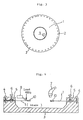
- Fig. 3 is a plane view of such a blade. In Fig.
- the reference numeral 1 designates a thin annular substrate disc of the steel prescribed herein.
- the reference numeral 9 designates a round hollow provided at the center of the substrate disc.
- the reference numeral 10 designates a blade edge consisting essentially of particulate diamond electrically deposited along inner peripheral edge portions of the annular disc.
- the annular disc is provided with a plurality of apertures 2 along its outer periphery. The apertures provide passages of bolts for mounting the saw blade on a slicing machine.
- the steel employed meets various requirements necessary as a substrate of a saw blade, without the necessity of drastic cold working that is required in the case of SUS301 and without the use of elements, such as A1, which may form harmful inclusions, that is required in the case of SUS631.
- the steel employed is designed so that properties necessary as a substrate of a saw blade may be imparted by a combination of work hardening by moderate cold working with age hardening using hardening elements which do not form inclusions. More particularly, the steel employed basically contains from 12.0% to 18.0% of Cr and from 4.0% to 8.0% of Ni.
- C is an austenite former, and is very effectively acts to suppress formation of delta-ferrite at an elevated temperature and to strengthen the martensitic phase induced by cold working.
- the increased Si in the steel employed lowers the solubility of C in the steel. Consequently, if C is excessively high, Cr carbide may precipitate in the grain boundaries, causing deterioration of inter-granular corrosion resistance and elongation. For this reason the upper limit for C is now set as 0.10%.
- Si is conventionally used for the purpose of deoxygenation of steels.
- the amount of Si added for the deoxygenation purpose is normally not more than 1.0%, as is the case with work hardening austenitic stainless steels, such as SUS301 and 304, and with precipitation hardening stainless steels, such as SUS631.
- Si serves to strengthen and harden the formed martensitic phase, and also dissolves in the retained austenitic phase to strengthen the latter, whereby strength of the cold worked steel may be further increased.
- more than 1.0% of Si is required.
- Si in excess of 3.0% crackings may appear at an elevated temperature, posing difficulties in the sheet making process. For these reasons, Si is now set as more than 1.0% but not more than 3.0%.
- Mn is an element which determines stability of auspare, and utilization of Mn should be considered in balance with other elements. In the case of the invention an unduly high Mn content adversely affects elongation of the disc. Accordingly, we set Mn as less than 0.5%.
- Ni is essential to obtain an austenitic phase at elevated and ambient temperatures. In the case of the steel employed, it is essential to provide an austenitic phase which is quasi-stable at ambient temperature and from which a martensitic phase may be induced by cold working. If the Ni content is substantially less than 4.0%, delta-ferrite tends to be formed at an elevated temperature and the austenite phase does not easily become quasi-stable at ambient temperature. On the other hand, if the Ni content substantially exceeds 8.0%, it becomes difficult to induce martensite by cold working. For these reasons Ni is set at from 4.0% to 8.0%.
- Cr is added to render the blade substrate corrosion resistant.
- at least 12.0% of Cr is required.
- austenite formers such as C, N, Ni, Mn and Cu
- the balance of Cr and austenite formers is important.
- up to 18.0% of Cr is permissible provided that the steel contains C, N, Ni, Mn and Cu in amounts prescribed herein. Accordingly, we set the upper limit for Cr at 18.0%.
- Cu as described here-in-before, cooperates with Si upon age hardening heat treatment to strengthen the steel. For appreciable effect at least 0.5% of Cu is required. On the other hand, unduly high Cu may be a cause of cracking. Cu is set as from 0.5% to 3.5%.
- N is an austenite former, and very effectively acts to harden both the austenitic and martensitic phases.
- unduly high N may be s cause of formation of blow holes upon casting.
- the upper limit for N is set as 0.15%.
- MnS in the presence of Mn, forms MnS, which may adversely affect elongation. While S is particularly harmful with the steel employed herein, 0.04% or less of S may be permitted as bringing about no actual harm. The upper limit for S is now set as 0.04%.
- C and N similarly operate and bring about similar effects.
- they are interexchangable, and it is necessary that the sum of them is at least a certain level.
- the steel employed consists essentially of, by weight, not more than 0.10 % of C, more than 1.0 % but not more than 3.0 % of Si, less than 0.5 % of Mn, from 4.0 % to 8.0 % of Ni, from 12.0 % of 18.0 % of Cr, from 0.5 % to 3.5 % of Cu, not more than 0.15 % of N and not more than 0.04 % of S, the sum of C and N being at least 0.10 %, the balance being Fe and unavoidable impurities.
- the thin sheet so prepared can be fabricated into a substrate disc by a method known per se .
- H1 to H7 steels prescribed herein ( H1 to H7), steels conventionally used (A to C) and control steels ( a to f), having chemical compositions indicated in Table 1, were cast, hot rolled in a usual manner and cold rolled at various reduction rates indicated in Tables 2-(1) and 2-(2) to prepare high strength cold rolled sheets.
- Specimens of the as rolled sheets were tested for amount of martensite induced by cold rolling ( alpha amount ), hardness, tensile strength and elongation.
- the sheets were age hardened under indicated conditions, and tested for hardness, tensile strength and elongation. Further, hardness differential, the difference between hardnesse before and after age hardening ( ⁇ H), was determined for each tested specimen.
- Tables 2 show that steels according to the invention contain higher amounts of martensite than conventionally used steels when cold rolled at the same or even lower reduction rate. It is understood that martensite is more liable to be induced by cold rolling with steels according to the invention than with conventionally used steels.
- steels according to the invention have higher tensile strength at the same level of elongation than conventionally used steels and control steels in both the as cold rolled and age hardened conditions. This means that tensile strength and elongation of steels according to the invention are superior to those of conventionally used work hardening austenitic and precipitation hardening stainless steels in both the as cold rolled and age hardened conditions. It is, therefore, possible to use a reduced reduction rated with steels according to the invention, ensuring better shape precision.
- Tables 1 and 2 show that steels having high Si and Cu exhibit large hardness differential, indicating synergistic cooperation of Si and Cu upon age hardening.
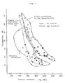
- Fig. 2 shows that Steel e having unduly high Mn and S contents has lower elongation in the age hardened condition than Steel H1 according to the invention, indicating the fact that excessively high Mn and S impair toughness of the final product.
- the blade so prepared was set on a chack body 3 ( slicing machine) as shown in Fig. 4.
- the setting was made by fixing outer periphery portions of the blade by passing bolts 4 through apertures 2 and tightening them, and thereafter pressing an O ring 5 against the annular disc 1 by means of bolts 6.
- a tension which would radially expand the inner periphery of the annular disc, was exerted.
- the radial expansion rate (RE%) of the inner periphery of the tensioned blade was determined by means of a microscope 7.
- a weight of 400 g was loaded on the tensioned blade at a position radially outwardly deviated by 5 mm from the inner periphery of the annular disc, and the amount of displacement of the blade due to the load was determined by means of an electro-micrometer 8.
- This amount of displacement (micron/400 g) is referred to herein as a Tension value T.
- the relationships between the radial expansion rate (RE%) and the tension value T provide a measure for determining a tension state of the blade necessary for slicing a rod material such as a single crystal of silicon.
- the results of the measurements on Steels H2 and A are shown in Fig. 5. Each steel was cold rolled at a reduction rate indicated in Fig. 5 and age hardened at 400°C for 1 hour.
- the disc does not reach the plastic deformation range at T values providing an optimum tension state of the blade, and even if further tensioned, the disc does not break ( see Fig. 5) since it has a considerable elongation. Even if the disc is deformed to some extent during service, it does not break, and is durable until the blade edge undergoes plastic deformation, whereby the number of wafers which can be prepared by a single blade may be increased (see Table 3). Further, when the disc has been deformed during service, it may be further tensioned to continue slicing, and thus, the service life is remarkably long. The same can be said for Steels H1 and H6. When compared with known saw blades wherein the disc substrate is made of steels conventionally used, the saw blades according to the invention have a long service life and are productive of many wafers ( see Table 3 ).
Landscapes
- Chemical & Material Sciences (AREA)
- Engineering & Computer Science (AREA)
- Materials Engineering (AREA)
- Mechanical Engineering (AREA)
- Metallurgy (AREA)
- Organic Chemistry (AREA)
- Mechanical Treatment Of Semiconductor (AREA)
- Lubrication Of Internal Combustion Engines (AREA)
- Magnetically Actuated Valves (AREA)
- Liquid Crystal Substances (AREA)
- Polishing Bodies And Polishing Tools (AREA)
- Heat Treatment Of Sheet Steel (AREA)
- Processing Of Stones Or Stones Resemblance Materials (AREA)
- Heat Treatment Of Steel (AREA)
Claims (2)
- Lame de tranchage comprenant un disque substrat et un bord de lame constitué d'une substance ultra-dure déposée le long d'un bord périphérique dudit disque substrat, caractérisée en ce que ledit disque substrat est fabriqué d'un acier constitué de, en poids, pas plus de 0,10% de C, plus de 1,0% mais pas plus de 3,0% de Si, moins de 0,5% de Mn, de 4,0% à 8,0% de Ni, de 12,0% à 18,0% de Cr, de 0,5% à 3,5% de Cu, pas plus de 0,15% de N et pas plus de 0,004% de S, la somme de C plus N étant d'au moins 0,10%, le complément étant du Fe et des impuretées inévitables.
- Lame de tranchage comprenant un disque substrat annulaire fin comportant un trou rond percé en son centre et un bord de lame constitué de diamant particulaire déposé le long de la périphérie interne dudit disque annulaire, caractérisée en ce que ledit disque substrat est fabriqué d'un acier constitué de ,en poids, pas plus de 0,10% de C, plus de 1,0% mais pas plus de 3% de Si, moins de 0,5% de Mn, de 4% à 8% de Ni, de 12,0% à 18,0% de Cr, de 0,5% à 3,5% de Cu, pas plus de 0,15% de N et pas plus de 0,004% de S, la somme de C plus N étant d'au moins de 0,10%, le complément étant du Fe et des impuretés inévitables.
Priority Applications (1)
| Application Number | Priority Date | Filing Date | Title |
|---|---|---|---|
| AT87902760T ATE81680T1 (de) | 1986-04-30 | 1987-04-30 | Trennblatt. |
Applications Claiming Priority (2)
| Application Number | Priority Date | Filing Date | Title |
|---|---|---|---|
| JP61100513A JPH07103445B2 (ja) | 1986-04-30 | 1986-04-30 | ブレ−ドの基板用ステンレス鋼 |
| JP100513/86 | 1986-04-30 |
Publications (3)
| Publication Number | Publication Date |
|---|---|
| EP0267295A1 EP0267295A1 (fr) | 1988-05-18 |
| EP0267295A4 EP0267295A4 (fr) | 1989-05-30 |
| EP0267295B1 true EP0267295B1 (fr) | 1992-10-21 |
Family
ID=14276029
Family Applications (1)
| Application Number | Title | Priority Date | Filing Date |
|---|---|---|---|
| EP87902760A Expired - Lifetime EP0267295B1 (fr) | 1986-04-30 | 1987-04-30 | Lame de tranchage |
Country Status (6)
| Country | Link |
|---|---|
| US (1) | US4847168A (fr) |
| EP (1) | EP0267295B1 (fr) |
| JP (1) | JPH07103445B2 (fr) |
| AT (1) | ATE81680T1 (fr) |
| DE (1) | DE3782311T2 (fr) |
| WO (1) | WO1987006625A1 (fr) |
Families Citing this family (9)
| Publication number | Priority date | Publication date | Assignee | Title |
|---|---|---|---|---|
| JP2537679B2 (ja) * | 1989-02-27 | 1996-09-25 | 日新製鋼株式会社 | 高強度ステンレス鋼およびその鋼材とその製造方法 |
| JPH02225647A (ja) * | 1989-02-27 | 1990-09-07 | Nisshin Steel Co Ltd | 高強度高延性ステンレス鋼材およびその製造方法 |
| JPH0436441A (ja) * | 1990-05-31 | 1992-02-06 | Nkk Corp | 高強度・高靭性ステンレス鋼およびその製造方法 |
| AT398176B (de) * | 1992-05-06 | 1994-10-25 | Boehler Ybbstalwerke | Bi-metall-bandrohling sowie daraus gefertigtes bi-metall-sägeblatt |
| US5494537A (en) * | 1994-02-21 | 1996-02-27 | Nisshin Steel Co. Ltd. | High strength and toughness stainless steel strip and process for the production of the same |
| DE10257967B4 (de) * | 2002-12-12 | 2006-04-13 | Stahlwerk Ergste Westig Gmbh | Verwendung einer Chrom-Stahllegierung |
| CN101456216B (zh) * | 2009-01-09 | 2011-08-10 | 博深工具股份有限公司 | 一种激光焊接金刚石圆锯片及制备方法 |
| TWI426939B (zh) * | 2011-01-13 | 2014-02-21 | Fusheng Prec L Co Ltd | 高爾夫球桿頭合金及其製造方法 |
| CN104907942B (zh) * | 2015-05-25 | 2017-08-29 | 江苏华昌工具制造有限公司 | 锯齿双面凹u锋利型混凝土激光焊接切割片的制备方法 |
Family Cites Families (11)
| Publication number | Priority date | Publication date | Assignee | Title |
|---|---|---|---|---|
| US3190047A (en) * | 1954-09-04 | 1965-06-22 | Villalobos Hum Fernandez-Moran | Method of making diamond knives |
| DE2214726A1 (de) * | 1972-03-25 | 1973-10-25 | Deutsche Edelstahlwerke Gmbh | Verwendung eines austenitischen nichtrostenden stahles fuer mit hohem verformungsgrad tiefgezogene gegenstaende |
| US3785787A (en) * | 1972-10-06 | 1974-01-15 | Nippon Yakin Kogyo Co Ltd | Stainless steel with high resistance against corrosion and welding cracks |
| JPS5129854B2 (fr) * | 1973-04-21 | 1976-08-27 | ||
| JPS527317A (en) * | 1975-07-08 | 1977-01-20 | Nippon Steel Corp | Stainless steel having excellent malleability |
| EP0002462A1 (fr) * | 1977-11-25 | 1979-06-27 | Jakob Lach Diamantwerkzeug-Fabrik | Dispositif de tronçonnage à dents de scie |
| US4222773A (en) * | 1979-05-29 | 1980-09-16 | Fagersta Ab | Corrosion resistant austenitic stainless steel containing 0.1 to 0.3 percent manganese |
| JPS5935412B2 (ja) * | 1980-03-19 | 1984-08-28 | 日新製鋼株式会社 | 析出硬化型ばね用ステンレス鋼素材の製法 |
| JPS56139662A (en) * | 1980-04-03 | 1981-10-31 | Nisshin Steel Co Ltd | Metallic conveyor belt and its manufacture |
| SE8102015L (sv) * | 1980-04-07 | 1981-10-08 | Armco Inc | Ferritfritt utskiljningsherdbart rostfritt stal |
| JPS61295356A (ja) * | 1985-06-24 | 1986-12-26 | Nisshin Steel Co Ltd | 高強度ステンレス鋼 |
-
1986
- 1986-04-30 JP JP61100513A patent/JPH07103445B2/ja not_active Expired - Fee Related
-
1987
- 1987-04-30 WO PCT/JP1987/000272 patent/WO1987006625A1/fr not_active Ceased
- 1987-04-30 AT AT87902760T patent/ATE81680T1/de active
- 1987-04-30 DE DE8787902760T patent/DE3782311T2/de not_active Expired - Fee Related
- 1987-04-30 US US07/144,341 patent/US4847168A/en not_active Expired - Lifetime
- 1987-04-30 EP EP87902760A patent/EP0267295B1/fr not_active Expired - Lifetime
Also Published As
| Publication number | Publication date |
|---|---|
| WO1987006625A1 (fr) | 1987-11-05 |
| US4847168A (en) | 1989-07-11 |
| EP0267295A1 (fr) | 1988-05-18 |
| ATE81680T1 (de) | 1992-11-15 |
| DE3782311T2 (de) | 1993-05-13 |
| JPH07103445B2 (ja) | 1995-11-08 |
| JPS62256949A (ja) | 1987-11-09 |
| EP0267295A4 (fr) | 1989-05-30 |
| DE3782311D1 (de) | 1992-11-26 |
Similar Documents
| Publication | Publication Date | Title |
|---|---|---|
| KR900006605B1 (ko) | 가공성이 우수하고 용접 연화가 없는 고강도 스테인레스 강재의 제조 방법 | |
| KR0175075B1 (ko) | 증기터빈용 회전자 및 그 제조방법 | |
| US4847168A (en) | Slicing saw blade | |
| US4058650A (en) | Back material of metal band saw high in fatigue strength | |
| US5032356A (en) | High fatigue strength metal band saw backing material | |
| KR960008890B1 (ko) | 고강도, 고인성 스텐레스 강판 및 그 제조방법 | |
| EP1757711B1 (fr) | Portions de machines carburées | |
| US5202089A (en) | Precipitation-hardenable tool steel | |
| JP2005082814A (ja) | プラスチック成形金型用プレハードン鋼 | |
| JPH04202643A (ja) | 高強度、高靭性ステンレス鋼およびその製造方法 | |
| JPH0555585B2 (fr) | ||
| JPS63317628A (ja) | 張り出し強度および靭性に優れた高強度ステンレス鋼の製造方法 | |
| JPS5937738B2 (ja) | 時効硬化性快削プラスチック金型用鋼 | |
| KR970009091B1 (ko) | 고 파쇄저항성 스텐레스 강판 및 그 제조방법 | |
| JPS5952227B2 (ja) | 高速度工具鋼 | |
| JP3735266B2 (ja) | 深冷処理用高強度ステンレス鋼 | |
| JP4396561B2 (ja) | 高周波焼入れ用鋼 | |
| JPH07316662A (ja) | 高強度高靱性ステンレス鋼帯の製造方法 | |
| JP3219117B2 (ja) | Idソーブレード板用ステンレス鋼帯及びその製造方法 | |
| US4975242A (en) | Carbon steel for machine structural use | |
| JPH0641686A (ja) | Idブレード用ステンレス鋼薄板およびその製造方法 | |
| JPH06212365A (ja) | 帯鋸用鋼材およびその製造方法 | |
| JPH07258733A (ja) | Idブレード用高強度ステンレス鋼薄板およびその製造 方法 | |
| JP7436826B2 (ja) | 窒化部品及び窒化部品の製造方法 | |
| JPH0672256B2 (ja) | オーステナイト系ステンレスクラッド鋼板の製造方法 |
Legal Events
| Date | Code | Title | Description |
|---|---|---|---|
| PUAI | Public reference made under article 153(3) epc to a published international application that has entered the european phase |
Free format text: ORIGINAL CODE: 0009012 |
|
| AK | Designated contracting states |
Kind code of ref document: A1 Designated state(s): AT BE DE FR GB NL SE |
|
| 17P | Request for examination filed |
Effective date: 19880504 |
|
| A4 | Supplementary search report drawn up and despatched |
Effective date: 19890530 |
|
| 17Q | First examination report despatched |
Effective date: 19910114 |
|
| GRAA | (expected) grant |
Free format text: ORIGINAL CODE: 0009210 |
|
| AK | Designated contracting states |
Kind code of ref document: B1 Designated state(s): AT BE DE FR GB NL SE |
|
| REF | Corresponds to: |
Ref document number: 81680 Country of ref document: AT Date of ref document: 19921115 Kind code of ref document: T |
|
| REF | Corresponds to: |
Ref document number: 3782311 Country of ref document: DE Date of ref document: 19921126 |
|
| ET | Fr: translation filed | ||
| PLBE | No opposition filed within time limit |
Free format text: ORIGINAL CODE: 0009261 |
|
| STAA | Information on the status of an ep patent application or granted ep patent |
Free format text: STATUS: NO OPPOSITION FILED WITHIN TIME LIMIT |
|
| 26N | No opposition filed | ||
| EAL | Se: european patent in force in sweden |
Ref document number: 87902760.5 |
|
| PGFP | Annual fee paid to national office [announced via postgrant information from national office to epo] |
Ref country code: SE Payment date: 20010404 Year of fee payment: 15 |
|
| PGFP | Annual fee paid to national office [announced via postgrant information from national office to epo] |
Ref country code: FR Payment date: 20010409 Year of fee payment: 15 |
|
| PGFP | Annual fee paid to national office [announced via postgrant information from national office to epo] |
Ref country code: AT Payment date: 20010411 Year of fee payment: 15 |
|
| PGFP | Annual fee paid to national office [announced via postgrant information from national office to epo] |
Ref country code: DE Payment date: 20010423 Year of fee payment: 15 |
|
| PGFP | Annual fee paid to national office [announced via postgrant information from national office to epo] |
Ref country code: GB Payment date: 20010425 Year of fee payment: 15 |
|
| PGFP | Annual fee paid to national office [announced via postgrant information from national office to epo] |
Ref country code: NL Payment date: 20010430 Year of fee payment: 15 |
|
| PGFP | Annual fee paid to national office [announced via postgrant information from national office to epo] |
Ref country code: BE Payment date: 20010625 Year of fee payment: 15 |
|
| REG | Reference to a national code |
Ref country code: GB Ref legal event code: IF02 |
|
| PG25 | Lapsed in a contracting state [announced via postgrant information from national office to epo] |
Ref country code: GB Free format text: LAPSE BECAUSE OF NON-PAYMENT OF DUE FEES Effective date: 20020430 Ref country code: BE Free format text: LAPSE BECAUSE OF NON-PAYMENT OF DUE FEES Effective date: 20020430 Ref country code: AT Free format text: LAPSE BECAUSE OF NON-PAYMENT OF DUE FEES Effective date: 20020430 |
|
| PG25 | Lapsed in a contracting state [announced via postgrant information from national office to epo] |
Ref country code: SE Free format text: LAPSE BECAUSE OF NON-PAYMENT OF DUE FEES Effective date: 20020501 |
|
| PG25 | Lapsed in a contracting state [announced via postgrant information from national office to epo] |
Ref country code: NL Free format text: LAPSE BECAUSE OF NON-PAYMENT OF DUE FEES Effective date: 20021101 Ref country code: DE Free format text: LAPSE BECAUSE OF NON-PAYMENT OF DUE FEES Effective date: 20021101 |
|
| GBPC | Gb: european patent ceased through non-payment of renewal fee |
Effective date: 20020430 |
|
| PG25 | Lapsed in a contracting state [announced via postgrant information from national office to epo] |
Ref country code: FR Free format text: LAPSE BECAUSE OF NON-PAYMENT OF DUE FEES Effective date: 20021231 |
|
| NLV4 | Nl: lapsed or anulled due to non-payment of the annual fee |
Effective date: 20021101 |
|
| EUG | Se: european patent has lapsed | ||
| REG | Reference to a national code |
Ref country code: FR Ref legal event code: ST |