EP0267316B1 - Schloss - Google Patents
Schloss Download PDFInfo
- Publication number
- EP0267316B1 EP0267316B1 EP86115737A EP86115737A EP0267316B1 EP 0267316 B1 EP0267316 B1 EP 0267316B1 EP 86115737 A EP86115737 A EP 86115737A EP 86115737 A EP86115737 A EP 86115737A EP 0267316 B1 EP0267316 B1 EP 0267316B1
- Authority
- EP
- European Patent Office
- Prior art keywords
- lock
- key
- cross
- keyhole
- section
- Prior art date
- Legal status (The legal status is an assumption and is not a legal conclusion. Google has not performed a legal analysis and makes no representation as to the accuracy of the status listed.)
- Expired - Lifetime
Links
- 230000004323 axial length Effects 0.000 claims abstract description 4
- 239000002184 metal Substances 0.000 claims description 18
- 230000000630 rising effect Effects 0.000 claims description 3
- 230000001174 ascending effect Effects 0.000 abstract 1
- 230000001681 protective effect Effects 0.000 description 4
- 238000006073 displacement reaction Methods 0.000 description 3
- 238000000034 method Methods 0.000 description 3
- 230000008878 coupling Effects 0.000 description 2
- 238000010168 coupling process Methods 0.000 description 2
- 238000005859 coupling reaction Methods 0.000 description 2
- 208000006083 Hypokinesia Diseases 0.000 description 1
- 230000000295 complement effect Effects 0.000 description 1
- 230000007812 deficiency Effects 0.000 description 1
- 238000005553 drilling Methods 0.000 description 1
- 230000000149 penetrating effect Effects 0.000 description 1
- 239000007787 solid Substances 0.000 description 1
Images

Classifications
-
- E—FIXED CONSTRUCTIONS
- E05—LOCKS; KEYS; WINDOW OR DOOR FITTINGS; SAFES
- E05B—LOCKS; ACCESSORIES THEREFOR; HANDCUFFS
- E05B19/00—Keys; Accessories therefor
- E05B19/0017—Key profiles
-
- E—FIXED CONSTRUCTIONS
- E05—LOCKS; KEYS; WINDOW OR DOOR FITTINGS; SAFES
- E05B—LOCKS; ACCESSORIES THEREFOR; HANDCUFFS
- E05B15/00—Other details of locks; Parts for engagement by bolts of fastening devices
- E05B15/16—Use of special materials for parts of locks
- E05B15/1614—Use of special materials for parts of locks of hard materials, to prevent drilling
-
- E—FIXED CONSTRUCTIONS
- E05—LOCKS; KEYS; WINDOW OR DOOR FITTINGS; SAFES
- E05B—LOCKS; ACCESSORIES THEREFOR; HANDCUFFS
- E05B19/00—Keys; Accessories therefor
- E05B19/0017—Key profiles
- E05B19/0041—Key profiles characterized by the cross-section of the key blade in a plane perpendicular to the longitudinal axis of the key
- E05B19/0047—Key profiles characterized by the cross-section of the key blade in a plane perpendicular to the longitudinal axis of the key with substantially circular or star-shape cross-section
-
- Y—GENERAL TAGGING OF NEW TECHNOLOGICAL DEVELOPMENTS; GENERAL TAGGING OF CROSS-SECTIONAL TECHNOLOGIES SPANNING OVER SEVERAL SECTIONS OF THE IPC; TECHNICAL SUBJECTS COVERED BY FORMER USPC CROSS-REFERENCE ART COLLECTIONS [XRACs] AND DIGESTS
- Y10—TECHNICAL SUBJECTS COVERED BY FORMER USPC
- Y10T—TECHNICAL SUBJECTS COVERED BY FORMER US CLASSIFICATION
- Y10T70/00—Locks
- Y10T70/70—Operating mechanism
- Y10T70/7441—Key
- Y10T70/7486—Single key
- Y10T70/7508—Tumbler type
- Y10T70/7559—Cylinder type
- Y10T70/7565—Plural tumbler sets
-
- Y—GENERAL TAGGING OF NEW TECHNOLOGICAL DEVELOPMENTS; GENERAL TAGGING OF CROSS-SECTIONAL TECHNOLOGIES SPANNING OVER SEVERAL SECTIONS OF THE IPC; TECHNICAL SUBJECTS COVERED BY FORMER USPC CROSS-REFERENCE ART COLLECTIONS [XRACs] AND DIGESTS
- Y10—TECHNICAL SUBJECTS COVERED BY FORMER USPC
- Y10T—TECHNICAL SUBJECTS COVERED BY FORMER US CLASSIFICATION
- Y10T70/00—Locks
- Y10T70/70—Operating mechanism
- Y10T70/7441—Key
- Y10T70/7486—Single key
- Y10T70/7508—Tumbler type
- Y10T70/7559—Cylinder type
- Y10T70/7588—Rotary plug
- Y10T70/7593—Sliding tumblers
- Y10T70/7599—Transverse of plug
- Y10T70/7605—Pin tumblers
-
- Y—GENERAL TAGGING OF NEW TECHNOLOGICAL DEVELOPMENTS; GENERAL TAGGING OF CROSS-SECTIONAL TECHNOLOGIES SPANNING OVER SEVERAL SECTIONS OF THE IPC; TECHNICAL SUBJECTS COVERED BY FORMER USPC CROSS-REFERENCE ART COLLECTIONS [XRACs] AND DIGESTS
- Y10—TECHNICAL SUBJECTS COVERED BY FORMER USPC
- Y10T—TECHNICAL SUBJECTS COVERED BY FORMER US CLASSIFICATION
- Y10T70/00—Locks
- Y10T70/70—Operating mechanism
- Y10T70/7441—Key
- Y10T70/778—Operating elements
- Y10T70/7791—Keys
- Y10T70/7842—Single shank or stem
-
- Y—GENERAL TAGGING OF NEW TECHNOLOGICAL DEVELOPMENTS; GENERAL TAGGING OF CROSS-SECTIONAL TECHNOLOGIES SPANNING OVER SEVERAL SECTIONS OF THE IPC; TECHNICAL SUBJECTS COVERED BY FORMER USPC CROSS-REFERENCE ART COLLECTIONS [XRACs] AND DIGESTS
- Y10—TECHNICAL SUBJECTS COVERED BY FORMER USPC
- Y10T—TECHNICAL SUBJECTS COVERED BY FORMER US CLASSIFICATION
- Y10T70/00—Locks
- Y10T70/70—Operating mechanism
- Y10T70/7441—Key
- Y10T70/778—Operating elements
- Y10T70/7791—Keys
- Y10T70/7881—Bitting
-
- Y—GENERAL TAGGING OF NEW TECHNOLOGICAL DEVELOPMENTS; GENERAL TAGGING OF CROSS-SECTIONAL TECHNOLOGIES SPANNING OVER SEVERAL SECTIONS OF THE IPC; TECHNICAL SUBJECTS COVERED BY FORMER USPC CROSS-REFERENCE ART COLLECTIONS [XRACs] AND DIGESTS
- Y10—TECHNICAL SUBJECTS COVERED BY FORMER USPC
- Y10T—TECHNICAL SUBJECTS COVERED BY FORMER US CLASSIFICATION
- Y10T70/00—Locks
- Y10T70/70—Operating mechanism
- Y10T70/7441—Key
- Y10T70/7915—Tampering prevention or attack defeating
- Y10T70/7932—Anti-pick
-
- Y—GENERAL TAGGING OF NEW TECHNOLOGICAL DEVELOPMENTS; GENERAL TAGGING OF CROSS-SECTIONAL TECHNOLOGIES SPANNING OVER SEVERAL SECTIONS OF THE IPC; TECHNICAL SUBJECTS COVERED BY FORMER USPC CROSS-REFERENCE ART COLLECTIONS [XRACs] AND DIGESTS
- Y10—TECHNICAL SUBJECTS COVERED BY FORMER USPC
- Y10T—TECHNICAL SUBJECTS COVERED BY FORMER US CLASSIFICATION
- Y10T70/00—Locks
- Y10T70/80—Parts, attachments, accessories and adjuncts
- Y10T70/8432—For key-operated mechanism
- Y10T70/8595—Key guides, internal
-
- Y—GENERAL TAGGING OF NEW TECHNOLOGICAL DEVELOPMENTS; GENERAL TAGGING OF CROSS-SECTIONAL TECHNOLOGIES SPANNING OVER SEVERAL SECTIONS OF THE IPC; TECHNICAL SUBJECTS COVERED BY FORMER USPC CROSS-REFERENCE ART COLLECTIONS [XRACs] AND DIGESTS
- Y10—TECHNICAL SUBJECTS COVERED BY FORMER USPC
- Y10T—TECHNICAL SUBJECTS COVERED BY FORMER US CLASSIFICATION
- Y10T70/00—Locks
- Y10T70/80—Parts, attachments, accessories and adjuncts
- Y10T70/8432—For key-operated mechanism
- Y10T70/8622—Key insertion guides
Definitions
- the invention relates to a lock with associated key, an outer housing, a lock cylinder rotatably mounted therein with a coaxial, cross-sectionally round key channel and with several rows of radial bores for receiving the tumbler pins and their springs, the key on its outer profile notches for the Has a hold of a tumbler.
- a locking cylinder allows more locking variations than are provided by rows of pins consisting of one or more pins.
- a corresponding row of notches for receiving the tips of the pins is provided on the key for each row of tumbler pins of the lock.
- the foremost, radially directed pins in the lock execute a number of radial movements reduced by one, as notches are arranged in the respectively associated row of the key.
- the foremost pin falls into all the notches one after the other and must be lifted out of all the previous notches into which it has fallen until it finally rests in the notch of the key assigned to it.
- One consequence is the often characteristic pin flattening for such locks and the associated noise as well as vibrations when handling the key in the lock.
- a circular cylindrical key is inserted into a congruent circular keyhole, the key not being guided, which impairs the reliability of the locking function; this is especially true of the pens.
- the key head is tapered and therefore cannot snap into place and cannot transmit any torque to the cylinder.
- the sensitive cylinder which is not covered from the outside by the housing, i.e. is visible, can therefore be easily damaged.
- the key has a shaft part with an equilateral polygonal cross-section, which corresponds to the cross-section of the keyhole in the housing end wall and a coaxial recess in the lock cylinder base, and when Inserting the head of the shaft part into the recess of the bottom of the lock cylinder locks the key and the lock cylinder, these cross sections of the keyhole and bottom recess being angularly offset from one another, and that on the head of the shaft part corresponding to the rows of the tumbler pins, rising towards the key handle and in each case one Polygonal tapered surfaces for lifting the tumbler pins and the rows of notches are arranged between the polygonal surfaces of the shaft part, the axial length of the polygonal shaft part of the key ssels is not greater than the length of the key channel in the lock cylinder and the subsequent shaft part in the keyhole is rotatable.
- the lock design according to the invention uses a solid key which, in contrast to known key designs, has a polygonal shaft cross-section, which means both a triangular and polygonal cross-section.
- the cross-section of this shaft part corresponds to the cross-section of the keyhole in the front of the housing, which covers the locking cylinder to the outside in the lock according to the invention.
- the polygonal cross section of the shaft part also corresponds to the cross section of a recess in the bottom of the lock cylinder which is coaxial to the keyhole. Despite their coaxial arrangement, the two polygonal cross sections of the recess and the keyhole are not congruent, but rather offset by a certain angle.
- the key if it should engage in the bottom recess, must first perform a rotation corresponding at least to this angular displacement.
- the shaft part with the rows of the locking pins corresponding and rising towards the key handle and on each polygonal surface of the shaft cross-section sloping surfaces for lifting the locking pins are arranged, whereas the rows of the notches of the key receiving the tips of the locking pins between the polygonal surfaces, i.e. practically open an edge arranged between two polygonal surfaces.
- each inclined surface of the key head When the key is inserted into the cross-sectionally round key channel, each inclined surface of the key head successively engages under all the pins of a row and lifts them onto the polygonal surfaces running parallel to the key axis, without the pins falling into a notch because they slide along the polygonal surfaces of the shaft part . Since the polygonal key is rotatably guided in the keyhole having the same polygonal cross-section, it can at most be inserted into the lock up to the stop at the bottom of the lock cylinder without being able to engage in the bottom recess, since its cross-section corresponding to the shaft cross-section is arranged at an angle.
- each pin is raised in the radial direction only once, but in two stages to the maximum height, from which it then falls into the notch of the key assigned to it.
- the movements of the tumbler pins are thus reduced to a mid-size and thus wear is effectively reduced, which benefits the lifespan of the lock and the securing of its functionality and lifespan.
- the key rotation within the lock is made possible by a limited length of the polygonal cross-section and the rotatability of the adjoining part of the key shaft within the keyhole.
- each tumbler pin is raised only once, in a first stage with an axial key movement out of the notch, the key head also emerging from the bottom recess. If the key is then rotated again at a certain angle about its longitudinal axis in the key channel, the tumbler pins of each row come to rest on one of the polygonal surfaces of the shaft part. If the key is now pulled out further, one pin after the other runs radially inwards over the inclined surface on the key head, which serves as a ramp, to its predefined inner end position.
- the correspondence between the cross section of the key and the recess in the bottom of the lock cylinder causes the lock cylinder to be carried along by the rotating key when the key has reached its axial end position within the lock and the key head has entered the bottom recess.
- Such a lock is not only extremely low-wear, as explained, but also satisfies the highest security demands.
- the number of rows of the tumbler pins corresponds to the number of polygonal surfaces of the switching part of the key, although more polygonal areas than rows of tumbler pins can also be provided. It is within the scope of the invention that two or more rows of tumbler pins are provided and cross-sectionally form an uneven polygon. This measure results in an asymmetrical lock structure, which in turn serves for increased security.
- the spring tension given to the tumbler pins means that the key inserted to the bottom of the locking cylinder then only needs a small angular momentum to cover the last part of its axial movement within the key channel.
- a further measure to increase the security of such a lock is provided by the invention in that a rotatable ring disk made of hard metal is arranged between the front side of the housing and the cylinder, ie on the inside of the front side of the housing. This creates an effective protection against the attempt to open the lock.
- This hard metal ring not only protects the locking cylinder, it also completely hides it on the end.
- this hard metal disc has a central bore for the lock coupling.
- the tumbler pins mounted in the locking cylinder consist of hard metal.
- the hard metal pins will provide the drill with the greatest possible resistance.
- the invention provides for carbide pins to be inserted axially immovably in some radial bores of the locking cylinder.
- a protective plate with an internal fastening on the outside of the lock, which has an opening aligned with the keyhole and on its inside a recess that receives the end face of the lock.
- a protective plate completely covers the lock and offers the guarantee that such a lock can meet the highest security requirements. Possibly.
- this protective plate can itself be made of hard metal.
- a hard metal disk is rotatably mounted in the part of the recess covering the locking cylinder on the inside of the protective plate. In addition to the annular disk arranged between the housing end wall and the lock cylinder, this can also be provided in its place, if necessary, also in its place. In any case, this feature serves the satisfaction of the highest security requirements for the castle.
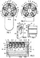
- the lock shown in the drawing consists of a housing 1 and a lock cylinder 2 mounted concentrically therein with a central key channel 3 of circular cross section.
- the housing 1 has on its outside an end wall 4 which carries the keyhole 5 coaxial to the key channel 3 and completely covers the annular end face 6 of the locking cylinder 2.
- the lock shown in the drawing has five rows of radial bores 7 penetrating the cylindrical housing 1 and the locking cylinder 2 into the key channel 3.
- the row shown in FIG. 3 in longitudinal section consists, for example, of five such bores 7.
- Each radial bore 7 leads a tumbler pin 8, which consists of an inner guide part 9 and an outer locking part 10.
- the guide part 9 has a shoulder-like shoulder 11, which interacts with a shoulder 12 in the bore 7 and limits the radially inward movement of the tumbler pins.
- the head 12 of the guide part 9 which bears against the locking part 10 is rounded flat.
- a helical spring 15 acts on the radially outer surface 14 of the outer part 10. This rests on the outside on a sleeve 16 which is pushed onto the cylindrical housing 1 and fastened thereon, and thus closes the radial bores 7 to the outside.
- the housing 1 and the sleeve 16 complement each other to form a firmly connected unit.
- the locking cylinder 2 is provided with a bottom 20.
- This has a recess 21 which is coaxial with the key channel 3 and the keyhole 5 in the end wall 4 of the housing 1.
- Both this recess 21 and the keyhole 5 are provided with an equilateral pentagonal cross-section, in the place of which a triangle or polygon can also occur.
- the pentagonal cross-sections of the keyhole 5 and the bottom recess 21 are angularly offset from one another by 36 ° .
- the associated key 22 has a front shaft part 23 of a pentagonal cross-section (see FIG. 8), the pentagon of this cross-section corresponding to that of the keyhole 5 and the bottom recess 21 of the lock cylinder 2.
- the axial length 24 of the pentagonal shaft part 23 of the key 22 corresponds approximately to the length 25 of the key channel 3 in the locking cylinder 2 to the bottom 20.
- the subsequent shaft part 26 of the key 22 can be rotated with a round cross section and in the keyhole 5.
- the shaft part 23 of the key 22 has an inclined surface 29 for each pentagonal surface 28, which rises towards the key handle 30 and ends on a polygonal surface 28. This gives the end face 31 of this shaft part 23 a stem shape, as shown in FIGS. 5 and 9.
- a row of notches 33 is arranged on each edge 32 of this pentagonal shaft part 23, each of which is assigned to one of the tumbler pins 8.
- annular disk 34 made of hard metal is provided between the latter and the end face 6 of the locking cylinder 2.
- a corresponding hard metal disk 35 is provided on the rear of the lock cylinder base 20. This has a central bore 36 for the lock coupling. Possibly.
- the locking parts 10 of individual tumbler pins 8 can also be made of hard metal and be arranged axially immovably in their radial bore 7, as is the case, for example, with the guide part 9 ' , which protrudes as a key, as shown in FIG. 1.
- the key 22 is inserted with its head 27 into the keyhole 5 in a predetermined pivoting position.
- the key handle 30 assumes an inclined position relative to the housing extension 38.
- the tips 17 of the foremost locking pins 8 of all rows run onto the ramp-like inclined surfaces 29 of the key head 27 and are raised up to the level of the pentagonal surfaces 28 of the shaft part 23. This process is repeated for each further tumbler pin 8 following in the rows until all tumbler pins 8 of all rows rest on one of the pentagonal surfaces 28.
- the end wall 31 of the shaft part 23 strikes the bottom 20 of the locking cylinder 2.
- the key head 27 cannot engage in the recess 21 of the cylinder base because, due to the previous guidance through the keyhole 5, it has an angular position offset by 36 ° with respect to this recess 21 and which via the tips 17 of the locking pins 8 onto the pentagonal surfaces 28 of the shaft part 23 acting spring counteract a key turn.
- the entire length 24 of the shaft part 23 lies within the key channel 3 at this stage, and the stepped part 26 is located within the pentagonal key hole 5 of the housing end wall 4.
- the key 22 is now pivoted back by an angle of 36 ° , so that its pentagonal shaft part 23 is flush with the pentagonal cross section of the keyhole 5 and can be completely pulled out of the key channel 3.
- the tumbler pins 8 are lowered so that they rest on the pentagonal surfaces 28 of the shaft part 23.
- one locking pin 8 then follows the other of its row up to the inner end position, which is shown in FIG. 1, in which the locking parts 10 of the locking pins 8 block the locking cylinder 2 with respect to the housing 1.
- Fig. 10 shows an outer lock plate 40, which may also consist of hard metal and is attached from the inside of the door carrying the lock or the like. By means of the screws or the like. 41.
- This lock plate 40 has an opening 42 which is aligned with the keyhole 5 of the lock and, in the embodiment shown, also corresponds to the contours of the keyhole 5.
- the inside 43 of this key plate 40 has a recess 44, the shape of which is adapted to the end face of the lock and receives this end face in the assembly position shown in FIG. 8.
Landscapes
- Lock And Its Accessories (AREA)
- Pharmaceuticals Containing Other Organic And Inorganic Compounds (AREA)
- Acyclic And Carbocyclic Compounds In Medicinal Compositions (AREA)
- Supporting Of Heads In Record-Carrier Devices (AREA)
- Sheet Holders (AREA)
- Push-Button Switches (AREA)
Description
- Die Erfindung richtet sich auf ein Schloß mit zugehörigem Schlüssel, einem äußeren Gehäuse, einem drehbar darin gelagerten Schließzylinder mit einem koaxialen, querschnittlich runden Schlüsselkanal und mit mehreren Reihen von Radialbohrungen zur Aufnahme der Zuhaltestifte und deren Federn, wobei der Schlüssel an seinem Außenprofil Kerben für den Eignriff je eines Zuhaltestiftes aufweist.
- Bekanntlich läßt ein Schließzylinder umsomehr Schließvariationen zu, als aus einem oder mehreren Stiften bestehende Stiftreihen vorgesehen sind. Am Schlüssel ist für jede Reihe von Zuhaltestiften des Schlosses eine entsprechende Reihe von Kerben zur Aufnahme der Spitzen der Stifte vorgesehen.
- Beim Einführen des Schlüssels in den Schlüsselkanal führen die im Schloß vordersten, radial gerichteten Stifte eine um eins verminderte Zahl von Radialbewegungen aus, wie Kerben in der jeweils zugehörigen Reihe des Schlüssels angeordnet sind. Der vorderste Stift fällt nämlich nacheinander in sämtliche Kerben ein und muß, bis er schließlich in der ihm zugeordneten Kerbe des Schlüssels verweilt, aus allen vorhergehenden Kerben, in die er eingefallen ist, wieder herausgehoben werden. Für den nächsten Stift in dieser Reihe gilt entsprechendes, jedoch um eine Radialbewegung weniger usf. Daraus folgt eine hohe Abnutzung der Stifte. Diese ist um so größer, je weiter vom im Schloß sich die Zuhaltestifte befinden. Eine Folge ist, das für solche Schlösser vielfach charakteristische Stifteflattem und das damit verbundene Geräusch sowie Vibrationen bei der Handhabung des Schlüssels im Schloß.
- Gemäß einer bekannten Ausführung eines Sicherheitsschlosses mit Schließzylinder (FR-A 2 514 810) wird ein kreiszylindrischer Schlüssel in ein deckungsgleiches kreisförmiges Schlüsselloch eingeführt, wobei der Schlüssel nicht zwangsmäßig geführt wird, was die Zuverlässigkeit der Schließfunktion beeinträchtigt; dies trifft vor allem hinsichtlich der Stifte zu. Der Schlüssekopf ist kegelig geformt und kann deshalb an dieser Stelle nicht einrasten und kein Drehmoment auf den Zylinder übertragen. Der empfindliche Zylinder, welcher nach außenhin vom Gehäuse nicht verdeckt wird, also sichtbar ist, kann deshalb leicht beschädigt werden.
- Hieraus folgt die der Erfindung zugrunde liegende Aufgabe, den genannten Mangel der bekannten Schlösser abzuhelfen, damit den Verschleiß zu mindem und die Sicherheit solcher Schlösser wirksam zu erhöhen sowie schließlich einen besonders bedienungsfreundlichen, erschütterungsfreien Aufbau des Schlosses zu erzielen, ohne daß hierunter die Zahl der Schließvariationen leidet.
- Zur Lösung dieses Problems wird bei einem Schloß mit zugehörigem Schlüssel, welche die eingangs genannten Merkmale aufweisen, erfindungsgemäß vorgeschlagen, daß der Schlüssel einen Schaftteil mit gleichseitig mehreckigem Querschnitt aufweist, dem der Querschnitt des Schlüsselloches in der Gehäusestimwand und einer koaxialen Ausnehmung im Schließzylinderboden entspricht und beim Einführen des Kopfes des Schaftteils in die Ausnehmung des Schließzylinderbodens eine Verriegelung von Schlüssel und Schließzylinder erfolgt, wobei diese Querschnitte von Schlüsselloch und Bodenausnehmung gegeneinander winkelversetzt sind, und daß am Kopf des Schaftteils mit den Reihen der Zuhaltestifte korrespondierende, zum Schlüsselgriff hin ansteigende und auf je einer Mehreckfläche auslaufende Schrägflächen zum Anheben der Zuhaltestifte und die Reihen von Kerben zwischen den Mehreckflächen des Schaftteiles angeordnet sind, wobei die axiale Länge des mehreckigen Schaftteiles des Schlüssels nicht größer ist als die Länge des Schlüsselkanals im Schließzylinder und der anschließende Schaftteil im Schlüsselloch drehbar ist.
- Die erfindungsgemäße Schloßausbildung bedient sich eines massiven Schlüssels von im Gegensatz zu bekannten Schlüsselausbildungen mehreckigem Schaftquerschnitt, worunter sowohl ein dreieckiger als auch mehreckiger Querschnitt zu verstehen ist. Dem Querschnitt dieses Schaftteiles entspricht der Querschnitt des Schlüsselloches in der Gehäusestirnseite, die bei dem erfindungsgemäßen Schloß den Schließzylinder nach außen hin abdeckt. Dem Mehreckquerschnitt des Schaftteiles entspricht aber auch der Querschnitt einer zum Schlüsselloch koaxialen Ausnehmung im Schließzylinderboden. Die beiden Mehreckquerschnitte von Ausnehmung und Schlüsselloch sind jedoch trotz ihrer koaxialen Anordnung nicht deckungsgleich, vielmehr um einen bestimmten Winkel gegeneinander versetzt. Daraus folgt zwingend, daß der Schlüssel, soll er in die Bodenausnehmung eingreifen, zunächst eine zumindest dieser Winkelversetzung entsprechende Drehung durchführen muß. Am Kopf des Schaftteiles sind mit den Reihen der Zuhaltestifte korrespondierende und zum Schlüsselgriff hin ansteigende und auf je einer Mehreckflächen des Schaftquerschnitts auslaufende Schrägflächen zum Anheben der Zuhaltestifte angeordnet, wohingegen die Reihen der die Spitzen der Zuhaltestifte aufnehmenden Kerben des Schlüssels zwischen den Mehreckflächen, also praktisch auf einer zwischen zwei Mehreckflächen angeordneten Kante, verlaufen. Beim Einführen des Schlüssels in den querschnittlich runden Schlüsselkanal untergreift jede Schrägfläche des Schlüsselkopfes nacheinander sämtliche Stifte einer Reihe und hebt diese auf die parallel zur Schlüsselachse verlaufenden Mehreckflächen an, ohne daß hierbei die Stifte in eine Kerbe einfallen können, weil diese auf den Mehreckflächen des Schaftteiles entlanggleiten. Da der Mehreckschlüssel in dem den gleichen Mehreckquerschnitt aufweisenden Schlüsselloch unverdrehbar geführt wird, kann er allenfalls bis zum Anschlag am Boden des Schließzylinders in das Schloß eingeführt werden, ohne in die Bodenausnehmung eingreifen zu können, da deren dem Schaftquerschnitt entsprechender Querschnitt winkelversetzt angeordnet ist. Wird nun der Schlüssel um seine Längsachse um einen bestimmten Winkel verschwenkt, werden sämtliche Stifte der Stiftreihen gleichzeitig erneut angehoben und zwar auf eine Längskante des Mehreckquerschnitts des Schlüssels in unmittelbare axiale Nähe zu der dem einzelnen Stift zugeordneten Kerbe. Diese Schlüsseldrehung entspricht der Winkelversetzung zwischen Schlüsselloch und Bodenausnehmung. Da die Zuhaltestifte in bekannter Weise unter der Wirkung von zur Schloßachse gerichteten Federkräften stehen, drücken nunmehr die am Kerbenrand aufsitzenden Spitzen der Stifte den Schlüssel nach vom in die Bodenausnehmung hinein, so daß sie selbst in die ihnen zugeordnete Kerbe einfallen. Daraus folgt, daß bei dem erfindungsgemäßen Schloß ein jeder Stift-nur einfach, jedoch in zwei Stufen auf die maximale Höhe in radialer Richtung angehoben wird, von der er dann in die ihm zugeordnete Kerbe des Schlüssels einfällt. Die Bewegungen der Zuhaltestifte werden also auf ein Midestmaß reduziert und damit der Verschleiß wirksam vermindert, was der Lebensdauer des Schlosses und der Sicherung seiner Funktionsweise und Lebensdauer zugute kommt.
- Die Schlüsseldrehung innerhalb des Schlosses wird durch eine begrenzte Länge des Mehrkantquerschnittes und die Drehbarkeit des sich daran anschließenden Teils des Schlüsselschaftes innerhalb des Schlüssellochs ermöglicht.
- Der umgekehrte Vorgang spielt sich beim Abziehen des Schlüssels ab. Auch hierbei wird jeder Zuhaltestift nur ein einziges Mal angehoben und zwar in einer ersten Stufe bei axialer Schlüsselbewegung aus der Kerbe heraus, wobei der Schlüsselkopf zugleich aus der Bodenausnehmung austritt. Wird dann der Schlüssel wieder in bestimmten Winkel um seine Längsachse im Schlüsselkanal gedreht, kommen die Zuhaltestifte einer jeden Reihe auf einer der Mehrkantflächen des Schaftteiles zur Auflage. Wird nun der Schlüssel weiter herausgezogen, läuft ein Stift nach dem anderen über die als Rampe dienende Schrägfläche am Schlüsselkopf radial nach innen bis in seine vorgegebene inneren Endstellung. Die Korrespondenz des Querschnitts des Schlüssels mit der Ausnehmung im Schließzylinderboden bewirkt die Mitnahme des Schließzylinders durch den sich drehenden Schlüssel dann, wenn der Schlüssel seine axiale Endstellung innerhalb des Schlosses erreicht hat und der Schlüsselkopf in die Bodenausnehmung gelangt ist.
- Ein solches Schloß ist nicht nur, wie dargelegt, äußerst verschleißarm, sondern es befriedigt darüber hinaus höchste Sicherheitsansprüche.
- Im allgemeinen entspricht, wie die Erfindung nach einem weiteren Merkmal vorsieht, die Zahl der Reihen der Zuhaltestifte der Zahl der Mehreckflächen des Schaltteiles des Schlüssels, obwohl auch mehr Mehreckflächen als Reihen von Zuhaltestiften vorgesehen sein können. Es liegt im Rahmen der Erfindung, daß zwei oder mehr Reihen von Zuhaltestiften vorgesehen sind und querschnittlich ein ungleichseitiges Mehreck bilden. Durch diese Maßnahme wird ein unsymmetrischer Schloßaufbau erzielt, was wiederum der erhöhten Sicherheit dient.
- Als besonders vorteilhaft hat es sich im Rahmen der Erfindung erwiesen, daß die Winkelversetzung der Mehreckquerschnitte von Schlüsselloch und Bodenausnehmung

- Durch das Merkmal, daß das Gehäuse den Schließzylinder mit einer Gehäusestirnwand abdeckt, wird einem Manipulieren des Schlosses zuverlässig entgegengewirkt. Eine weitere Maßnahme, um die Sicherheit eines solchen Schlosses zu erhöhen, sieht die Erfindung dadurch vor, daß zwischen der Gehäusestirnseite und dem Zylinder, also an der Innenseite der Gehäusestimseite, eine drehbare Ringscheibe aus Hartmetall angeordnet ist. Hierdurch wird ein wirksamer Schutz gegen den Versuch das Schloß aufzubohren, geschaffen. Dieser Hartmetallring schützt nicht nur den Schließzylinder, er verdeckt ihn auch stirnseitig völlig. Es ist andererseits möglich, auch hinter dem Schließzylinderboden eine Hartmetallscheibe drehbar anzuordnen, um auch ein Aufbohren des Innenschlosses praktisch unmöglich zu machen. Sie bildet darüber hinaus einen wirksamen Schutz für den Schloßriegel. Die Drehbarkeit dieser Ringscheibe macht das Ansetzen eines Bohrers praktisch unmöglich. Im allgemeinen weist diese Hartmetallscheibe eine zentrale Bohrung für die Schließkupplung auf.
- Es liegt darüber hinaus im Rahmen dieses allgemeinen Gedankens der Erfindung, daß zumindest einige der in dem Schließzylinder gelagerten Zuhaltestifte aus Hartmetall bestehen. Im Falle eines Versuches, ein solches Schloß aufzubohren, werden die aus Hartmetall bestehenden Stifte dem Bohrer einen größtmöglichen Widerstand entgegensetzen. Als Alternative hierzu sieht die Erfindung schließlich vor, in einige Radialbohrungen des Schließzylinders Hartmetallstifte axial unbewegbar einzufügen.
- Es liegt im Rahmen der Erfindung, an der Außenseite des Schlosses eine Schutzplatte mit Innenbefestigung anzuordnen, die eine mit dem Schlüsselloch fluchtende Öffnung und an ihrer Innenseite eine die Stirnfläche des Schlosses aufnehmende Ausnehmung aufweist. Eine solche Schutzplatte deckt das Schloß völlig ab und bietet die Gewähr, daß ein solches Schloß höchsten Sicherheitsanforderungen zu entsprechen vermag. Ggf. kann diese Schutzplatte selbst aus Hartmetall bestehen. Es liegt im Rahmen dieses Gedankens der Erfindung, daß in dem den Schließzylinder abdeckenden Teil der Ausnehmung an der Innenseite der Schutzplatte eine Hartmetallscheibe drehbar gelagert ist. Diese kann zusätzlich zu der zwischen Gehäusestimwand und Schließzylinder angeordneten Ringscheibe, aber ggf., auch an deren Stelle angeordneten Ringscheibe, aber gf., auch an deren Stelle vorgesehen sein. In jedem Fall dient dieses Merkmal der Befriedigung höchster Sicherheitsansprüche für das Schloß.
- Weitere Merkmale, Einzelheiten und Vorteile der Erfindung ergeben sich aus der folgenden Beschreibung einer bevorzugten Ausführungsform der Erfindung sowie anhand der Zeichnung. Hierbei zeigen:
- Fig. 1 einen Querschnitt durch ein erfindungsgemäßes Schloß in Verriegelungsstellung des Schließzylinders gegenüber dem Gehäuse sowie
- Fig. 2 in Entriegelungsstellung;
- Fig. 3 einen Längsschnitt durch das Schloß nach den Fig. 1 und 2 etwa in Pfeilrichtung 111 in Fig. 1;
- Fig. 4 eine Stimansicht des Schlosses nach Fig. 1 bis 3 in Pfeilrichtung IV in Fig. 3;
- Fig. 5 eine Ansicht des Schlosses nach Fig. 3 in Pfeilrichtung V auf den Schließzylinderboden;
- Fig. 6 einen Schnitt etwa nach Linie VI-VI in Fig. 3;
- Fig. 7 den Schlüssel für das Schloß nach den Fig. 1 bis 6
- Fig. 8 einen Schnitt nach Linie VIII-VIII in Fig. 7;
- Fig. 9 eine perspektivische Darstellung des Schlüsselkopfes
- Fig. 10 eine Schloßplatte in perspektivischer Darstellung und
- Fig. 11 die Schloßplatte in Montagestellung mit einem Schloß.
- Das in der Zeichnung wiedergegebene Schloß besteht aus einem Gehäuse 1 und einem konzentrisch darin gelagerten Schließzylinder 2 mit einem mittigen Schlüsselkanal 3 von kreisförmigem Querschnitt. Das Gehäuse 1 weist an seiner Außenseite eine Stirnwand 4 auf, die das zum Schlüsselkanal 3 koaxiale Schlüsselloch 5 trägt und die ringförmige Stirnfläche 6 des Schließzylinders 2 völlig abdeckt. Das in der Zeichnung wiedergegebene Schloß weist fünf Reihen von das zylindrische Gehäuse 1 und den Schließzylinder 2 bis in den Schlüsselkanal 3 durchsetzende Radialbohrungen 7 auf. Die aus Fig. 3 im Längsschnitt ersichtliche Reihe besteht beispielsweise aus fünf solcher Bohrungen 7. Sowohl die Zahl der Reihen von Zuhaltestiften (in der Fig. 1 und 2 beispielsweise fünf Reihen) als auch die Zahl und die Lage der Zuhaltestifte je Reihe kann beliebig variiert und den Umständen des Einzelfalls angepaßt werden, was an sich bekannt ist. Jede Radialbohrung 7 führt einen Zuhaltestift 8, der aus einem inneren Führungsteil 9 und einem äußeren Verriegelungsteil 10 besteht. Der Führungsteil 9 weist eine schulterartige Absetzung 11 auf, die mit einem Absatz 12 in der Bohrung 7 zusammenwirkt und die radial nach innen gerichtete Bewegung der Zuhaltestifte begrenzt. Der dem Verriegelungsteil 10 anliegende Kopf 12 des Führungsteils 9 ist flach abgerundet. Auf die radial äußere Fläche 14 des äußeren Teils 10 wirkt eine Schraubenfeder 15. Diese stützt sich nach außen auf eine auf das zylindrische Gehäuse 1 aufgeschobene und daran befestigte Hülse 16, die damit die radialen Bohrungen 7 nach außen hin verschließt. Das Gehäuse 1 und die Hülse 16 ergänzen sich zu einer fest verbundenen Einheit.
- Der Schließzylinder 2 ist mit einem Boden 20 versehen. Dieser weist eine zum Schlüsselkanal 3 und zum Schlüsselloch 5 in der Stirnwand 4 des Gehäuses 1 koaxiale Ausnehmung 21 auf. Sowohl diese Ausnehmung 21, als auch das Schlüsselloch 5 sind mit einem gleichseitigen Fünfeckquerschnitt versehen, an dessen Stelle auch ein Dreieck oder Mehreck treten kann. Die Fünfeckquerschnitte von -Schlüsselloch 5 und Bodenausnehmung 21 sind jedoch um 36° gegeneinander winkelversetzt.
- Der zugehörige Schlüssel 22 weist einen vorderen Schaftteil 23 von gleichfalls fünfeckigem Querschnitt auf (s. Fig. 8), wobei das gleichseitige Fünfeck dieses Querschnittes etwa dem des Schlüssellochs 5 und der Bodenausnehmung 21 des Schließzylinders 2 entspricht. Die axiale Länge 24 des fünfeckigen Schaftteils 23 des Schlüssels 22 entspricht etwa der Länge 25 des Schlüsselkanals 3 im Schließzylinder 2 bis zum Boden 20. Der anschließende Schaftteil 26 des Schlüssels 22 ist beim wiedergegebenen Ausführungsbeispiel von rundem Querschnitt und in dem Schlüsselloch 5 drehbar. Im Bereich des Kopfes 27 weist der Schaftteil 23 des Schlüssels 22 für jede Fünfeckfläche 28 eine Schrägfläche 29 auf, die zum Schlüsselgriff 30 hin ansteigt und auf einer Mehreckfläche 28 ausläuft. Dadurch erhält die Stirnfläche 31 dieses Schaftteils 23 eine Stemform, wie in den Fig. 5 und 9 dargestellt ist. Auf jeder Kante 32 dieses fünfeckigen Schaftteiles 23 ist eine Reihe von Kerben 33 angeordnet, von denen jede einem der Zuhaltestifte 8 zugeordnet ist.
- An der Innenseite der Gehäusestimwand 4 ist zwischen dieser und der Stimfläche 6 des Schließzylinders 2 eine Ringscheibe 34 aus Hartmetall vorgesehen. Eine entsprechende Hartmetallscheibe 35 ist an der Rückseite des Schließzylinderbodens 20 vorgesehen. Diese weist eine zentrale Bohrung 36 für die Schließkupplung auf. Ggf. können auch die Verriegelungsteile 10 einzelner Zuhaltestifte 8 aus Hartmetall bestehen und axial unbewegbar in ihrer Radialbohrung 7 angeordnet sein, wie dies beispielsweise auf das Führungsteil 9', welches schlüsselbünding vorsteht, nach Fig. 1 zutrifft.
- Die Handhabung des Schlosses ist wie folgt:
- Der Schlüssel 22 wird mit seinem Kopf 27 in einer vorbestimmten Schwenkstellung in das Schlüsselloch 5 eingeführt. Hierbei nimmt der Schlüsselgriff 30 eine Schrägstellung zum Gehäusefortsatz 38 ein. Beim Einführen in den Schlüsselkanal 3 laufen die Spitzen 17 der vordersten Zuhaltestifte 8 sämtlicher Reihen auf die rampenartigen Schrägflächen 29 des Schlüsselkopfes 27 auf und werden hierbei bis auf Höhe der Fünfeckflächen 28 des Schaftteiles 23 angehoben. Dieser Vorgang wiederholt sich für jeden weiteren in den Reihen folgenden Zuhaltestifte 8, bis sämtliche Zuhaltestifte 8 aller Reihen auf je einer der Fünfeckflächen 28 aufruhen. In diesem Stadium trifft die Stirnwand 31 des Schaftteils 23 auf den Boden 20 des Schließzylinders 2 auf. Der Schlüsselkopf 27 kann jedoch nicht in die Ausnehmung 21 des Zylinderbodens eingreifen, weil er durch die vorherige Führung durch das Schlüsselloch 5 eine um 36° versetzte Winkelstellung gegenüber dieser Ausnehmung 21 aufweist und die über die Spitzen 17 der Zuhaltestifte 8 auf die Fünfeckflächen 28 des Schaftteils 23 einwirkenden Federkräfte einer Schlüsseldrehung entgegenwirken. Andererseits liegt zu diesem Stadium die gesamte Länge 24 des Schaftteiles 23 innerhalb des Schlüsselkanals 3, und der abgesetzte Teil 26 befindet sich innerhalb des fünfeckigen Schlüsselloches 5 der Gehäusestimwand 4. Durch eine erzwungene Schwenkung des Schlüssels 22 um seine Längsachse werden nunmehr die sämtlichen Zuhaltestifte 8 gleichzeitig um eine weitere Stufe angehoben und zwar bis auf die Höhe einer Seitenkante 32 des fünfeckigen Schaftteiles 23. Damit dreht sich aber auch das Fünfeck des Schlüsselkopfes 27 vor der Ausnehmung 21 des Zylinderbodens 20 derart, daß die beiden Elemente miteinander fluchten. Die Federspannung der Zuahltestifte 8 erreicht hier ihr Maximum und drückt diese mit ihren Spitzen 17 je in eine Kerbe 33 des Schaftteiles 23, so daß dieser eine kurze Axialbewegung ausführt und hierbei der Schlüsselkopf 27 in die Bodenausnehmung 21 einrastet. Dadurch ist der Schlüssel 22 mit dem Schließzylinder 2 verriegelt, und die sämtlichen beweglichen Zuhaltestifte 8 sind in die zugehörigen Kerben 33 des Schaftteiles 23 eingerastet. Dieser Zustand ist in Fig. 2 dargestellt. Hierbei befindet sich der Führungsteil 9 sämtlicher Zuhaltestifte 8 innerhalb des Schließzylinders 2, so daß dieser sich nunmehr bei weiterer Schlüsseldrehung mit diesem drehen läßt.
- Zum Öffnen des Schlosses läuft dieser Vorgang umgekehrt ab. In der vorbestimmten Drehstellung des Schließzylinders, in welchem die Radialbohrungen im Schließzylinder 2 und im Gehäuse 1 miteinander fluchten, wird der Schlüssel 22 durch Betätigung der Handhabe 30 soweit in axialer Richtung zurückgezogen, daß der fünfeckige Kopf 27 aus der Bodenausnehmung 21 des Schließzylinders 2 ausrastet. Hierdurch werden gleichzeitig sämtliche Zuhaltestifte 8, soweit sie in die Kerben 33 eingefallen waren, entgegen der Wirkung ihrer Federn angehoben. Sie ruhen zu diesem Zeitpunkt auf einer der Längskanten 32 des Schaftteils 23. Einer weiteren Schlüsselbewegung wirkt der Anschlag der Schulter 39 an der Innenseite des Schlüssellochs 5 entgegen. Deshalb wird nun der Schlüssel 22 um einen Winkel von 36° zurückverschwenkt, so daß sein fünfeckiges Schaftteil 23 mit dem Fünfeckquerschnitt des Schlüssellochs 5 fluchtet und vollends aus dem Schlüsselkanal 3 herausgezogen werden kann. Bei dieser geringfügigen Verschwenkung des Schlüssels senken sich die Zuhaltestifte 8 ab, so daß sie jeweils auf den Fünfeckflächen 28 des Schaftteiles 23 aufruhen. Beim Abziehen des Schlüssels aus dem Schlüsselloch 5 folgt dann ein Zuhaltestift 8 dem anderen seiner Reihe bis in die innere Endstellung, die in Fig. 1 dargestellt ist, in welcher die Verriegelungsteile 10 der Zuhaltestifte 8 den Schließzylinder 2 gegenüber dem Gehäuse 1 blockieren.
- Die Fig. 10 gibt eine äußere Schloßplatte 40 wieder, die ggf. auch aus Hartmetall bestehen kann und von der Innenseite der das Schloß tragenden Tür od. dgl. mittels der Schrauben od. dgl. 41 befestigt wird. Diese Schloßplatte 40 weist eine Öffnung 42 auf, die mit dem Schlüsselloch 5 des Schlosses fluchtet und bei der wiedergegebenen Ausführungsform auch den Konturen des Schlüsselloches 5 entspricht. Die Innenseite 43 dieser Schlüsselplatte 40 weist eine Ausnehmung 44 auf, deren Gestalt der Stirnfläche des Schlosses angepaßt ist und in der aus Fig. 8 ersichtlichen Montagestellung diese Stirnfläche aufnimmt.
- - Fig. 11 läßt erkennen, daß in dem axial vor dem Schließzylinder 2 liegenden Bereich 45 dieser Ausnehmung 44 eine Hartmetallscheibe 46 drehbar gelagert ist, die sich wirksam einem Aufbohrversuch wiedersetzt.
Claims (12)

Priority Applications (7)
| Application Number | Priority Date | Filing Date | Title |
|---|---|---|---|
| EP86115737A EP0267316B1 (de) | 1986-11-12 | 1986-11-12 | Schloss |
| ES86115737T ES2014222B3 (es) | 1986-11-12 | 1986-11-12 | Cerradura. |
| AT86115737T ATE50818T1 (de) | 1986-11-12 | 1986-11-12 | Schloss. |
| DE8686115737T DE3669338D1 (de) | 1986-11-12 | 1986-11-12 | Schloss. |
| CA000550887A CA1316362C (en) | 1986-11-12 | 1987-11-03 | Lock |
| JP62281943A JPH0656066B2 (ja) | 1986-11-12 | 1987-11-06 | 錠 |
| US07/118,147 US4770014A (en) | 1986-11-12 | 1987-11-06 | Lock |
Applications Claiming Priority (1)
| Application Number | Priority Date | Filing Date | Title |
|---|---|---|---|
| EP86115737A EP0267316B1 (de) | 1986-11-12 | 1986-11-12 | Schloss |
Publications (2)
| Publication Number | Publication Date |
|---|---|
| EP0267316A1 EP0267316A1 (de) | 1988-05-18 |
| EP0267316B1 true EP0267316B1 (de) | 1990-03-07 |
Family
ID=8195592
Family Applications (1)
| Application Number | Title | Priority Date | Filing Date |
|---|---|---|---|
| EP86115737A Expired - Lifetime EP0267316B1 (de) | 1986-11-12 | 1986-11-12 | Schloss |
Country Status (7)
| Country | Link |
|---|---|
| US (1) | US4770014A (de) |
| EP (1) | EP0267316B1 (de) |
| JP (1) | JPH0656066B2 (de) |
| AT (1) | ATE50818T1 (de) |
| CA (1) | CA1316362C (de) |
| DE (1) | DE3669338D1 (de) |
| ES (1) | ES2014222B3 (de) |
Families Citing this family (18)
| Publication number | Priority date | Publication date | Assignee | Title |
|---|---|---|---|---|
| US4981027A (en) * | 1988-03-01 | 1991-01-01 | Eb Metal Industries, Inc. | Three position lock mechanism for a vending machine |
| DE4000179A1 (de) * | 1990-01-05 | 1991-07-11 | Bks Gmbh | Schluessel fuer schliesszylinder, insbesondere von schliessanlagen |
| US5264401A (en) * | 1990-07-12 | 1993-11-23 | Lanxide Technology Company, Lp | Pressure assisted technique for forming self-supporting composite bodies and articles formed thereby |
| DE9314970U1 (de) * | 1993-10-02 | 1995-02-09 | Knauer, Helga, 91054 Erlangen | Schlüssellochverschluß für Schlösser mit einem Schlüssel mit mehreckigem Durchschnitt |
| US5531084A (en) * | 1993-12-06 | 1996-07-02 | The Eastern Company | Key for rotary plug and cylinder lock, and method of forming the key |
| US5485735A (en) * | 1993-12-06 | 1996-01-23 | The Eastern Company | Key operated rotary plug and cylinder lock |
| DE29818143U1 (de) * | 1998-10-10 | 2000-02-17 | Bks Gmbh, 42549 Velbert | Sicherheitsschlüssel |
| EP1607553B1 (de) * | 2004-06-15 | 2016-08-03 | ASSA ABLOY (Schweiz) AG | Schliesszylinder |
| DE102005042618A1 (de) | 2005-09-07 | 2007-03-08 | Huf Hülsbeck & Fürst GmbH & Co KG | Schließvorrichtung mit einem Schließzylinder und mit einem Schlüssel |
| DE102005042617A1 (de) | 2005-09-07 | 2007-03-15 | Huf Hülsbeck & Fürst Gmbh & Co. Kg | Schließvorrichtung mit einem Schließzylinder und mit einem Schlüssel |
| US7574882B2 (en) * | 2006-11-02 | 2009-08-18 | George Uliano | Tubular radial pin tumbler lock |
| US7673484B1 (en) * | 2007-01-24 | 2010-03-09 | Alois Crepinsek | Key lock assembly |
| DE102010017129A1 (de) * | 2010-03-09 | 2011-09-15 | Huf Hülsbeck & Fürst Gmbh & Co. Kg | Schließsystem |
| CN102635324B (zh) * | 2011-06-06 | 2015-04-22 | 黄江平 | 密匙孔控空转防盗锁及钥匙 |
| PL405478A1 (pl) * | 2013-09-30 | 2015-04-13 | Artur Litwiński | Mechanizm zamka z blokadą wyjęcia klucza i blokada wyjęcia klucza z mechanizmu zamka |
| TWI657183B (zh) * | 2017-10-13 | 2019-04-21 | 陳 譽詞 | 鎖心構造及鎖匙 |
| CN111082353B (zh) * | 2019-12-17 | 2021-12-17 | 上海平高天灵开关有限公司 | 箱变低压进线开关与发电车室共用闭锁结构及其闭锁方法 |
| JP7780928B2 (ja) * | 2021-12-01 | 2025-12-05 | 株式会社Lixil | シリンダ錠及びドア |
Family Cites Families (7)
| Publication number | Priority date | Publication date | Assignee | Title |
|---|---|---|---|---|
| US1477318A (en) * | 1922-07-05 | 1923-12-11 | George F Crass | Lock |
| DE2344473B2 (de) * | 1973-09-04 | 1976-04-29 | Josef Voss KG, 5040 Brühl | Zylinderkern in einem zylinderschloss mit flachschluessel |
| IT1040457B (it) * | 1975-08-04 | 1979-12-20 | Rimar Spa | Apparecchiatura e procedimento per la tintura in continuo di manufat ti tesseili in bagno di solvente |
| JPS572621Y2 (de) * | 1975-12-10 | 1982-01-18 | ||
| US4343126A (en) * | 1979-02-26 | 1982-08-10 | Hoofe Iii William J | Interlocking panels |
| US4338806A (en) * | 1979-06-03 | 1982-07-13 | Frank Catricola | Theft deterent lock |
| DE3140998A1 (de) * | 1981-10-15 | 1983-05-05 | Jiuan P. Taipei Taiwan Lo | Einbruchsicheres zylinderschloss |
-
1986
- 1986-11-12 DE DE8686115737T patent/DE3669338D1/de not_active Expired - Lifetime
- 1986-11-12 EP EP86115737A patent/EP0267316B1/de not_active Expired - Lifetime
- 1986-11-12 AT AT86115737T patent/ATE50818T1/de not_active IP Right Cessation
- 1986-11-12 ES ES86115737T patent/ES2014222B3/es not_active Expired - Lifetime
-
1987
- 1987-11-03 CA CA000550887A patent/CA1316362C/en not_active Expired - Fee Related
- 1987-11-06 JP JP62281943A patent/JPH0656066B2/ja not_active Expired - Lifetime
- 1987-11-06 US US07/118,147 patent/US4770014A/en not_active Expired - Fee Related
Also Published As
| Publication number | Publication date |
|---|---|
| JPH0656066B2 (ja) | 1994-07-27 |
| US4770014A (en) | 1988-09-13 |
| DE3669338D1 (de) | 1990-04-12 |
| CA1316362C (en) | 1993-04-20 |
| ATE50818T1 (de) | 1990-03-15 |
| ES2014222B3 (es) | 1990-07-01 |
| EP0267316A1 (de) | 1988-05-18 |
| JPS63171971A (ja) | 1988-07-15 |
Similar Documents
| Publication | Publication Date | Title |
|---|---|---|
| DE69005060T2 (de) | Zylinderschloss und Schlüssel. | |
| DE3516542C2 (de) | ||
| EP0267316A1 (de) | Schloss | |
| DE69410877T2 (de) | Schloss, bestehend aus einem Schlüssel und einem Zylinderschloss | |
| CH680520A5 (de) | ||
| CH620266A5 (de) | ||
| CH647296A5 (de) | Zylinderschloss mit zugehoerigem flachschluessel. | |
| DE4218683C2 (de) | Handstückkopf für ein zahnärztliches Handstück, mit einem Gehäuse, in dem ein Behandlungswerkzeug axial längs seiner Mittelachse hin und her verschiebbar gelagert ist | |
| EP0016903B1 (de) | Drehgriffeinheit | |
| EP0613987B1 (de) | Zylinderschloss und Flachschlüssel mit Steuernuten | |
| DE29514774U1 (de) | Betätigungshandhabe | |
| DE2625847A1 (de) | Kombinationsschloss fuer eingangstueren | |
| CH669011A5 (de) | Sicherheitsschloss. | |
| DE3410462A1 (de) | Schliesszylinder mit flachschluessel | |
| DE3641148C2 (de) | ||
| EP0581001B1 (de) | Fenstergriff | |
| DE2923598A1 (de) | Schliesszylinder und schliessanlage | |
| DE3642253A1 (de) | Abschliessbarer fenstergriff | |
| EP0449177B1 (de) | Schliesszylinder | |
| EP0811737B1 (de) | Zylinderschloss mit Zylinderkern | |
| DE9319981U1 (de) | Vorrichtung zur axial unverschieblichen, aber leicht lösbaren Verbindung eines Ausstattungsteils mit einem Montageteil | |
| DE29708489U1 (de) | Verriegelbare Betätigungsvorrichtung für Beschläge von Fenstern, Türen o.dgl. | |
| AT337034B (de) | Zylinderschloss mit einer sicherung gegen unbefugtes offnen | |
| DE2550242C2 (de) | Schließzylinder | |
| AT521007A2 (de) | Stiftzylinder-schlüssel-system und schlüssel dafür |
Legal Events
| Date | Code | Title | Description |
|---|---|---|---|
| PUAI | Public reference made under article 153(3) epc to a published international application that has entered the european phase |
Free format text: ORIGINAL CODE: 0009012 |
|
| AK | Designated contracting states |
Kind code of ref document: A1 Designated state(s): AT BE CH DE ES FR GB GR IT LI LU NL SE |
|
| 17P | Request for examination filed |
Effective date: 19880609 |
|
| 17Q | First examination report despatched |
Effective date: 19881014 |
|
| GRAA | (expected) grant |
Free format text: ORIGINAL CODE: 0009210 |
|
| RBV | Designated contracting states (corrected) |
Designated state(s): AT BE CH DE ES FR GB GR IT LI LU NL SE |
|
| AK | Designated contracting states |
Kind code of ref document: B1 Designated state(s): AT BE CH DE ES FR GB GR IT LI LU NL SE |
|
| PG25 | Lapsed in a contracting state [announced via postgrant information from national office to epo] |
Ref country code: GR Free format text: LAPSE BECAUSE OF FAILURE TO SUBMIT A TRANSLATION OF THE DESCRIPTION OR TO PAY THE FEE WITHIN THE PRESCRIBED TIME-LIMIT Effective date: 19900307 |
|
| REF | Corresponds to: |
Ref document number: 50818 Country of ref document: AT Date of ref document: 19900315 Kind code of ref document: T |
|
| REF | Corresponds to: |
Ref document number: 3669338 Country of ref document: DE Date of ref document: 19900412 |
|
| ITF | It: translation for a ep patent filed | ||
| GBT | Gb: translation of ep patent filed (gb section 77(6)(a)/1977) | ||
| ET | Fr: translation filed | ||
| PG25 | Lapsed in a contracting state [announced via postgrant information from national office to epo] |
Ref country code: LU Free format text: LAPSE BECAUSE OF NON-PAYMENT OF DUE FEES Effective date: 19901130 |
|
| PLBE | No opposition filed within time limit |
Free format text: ORIGINAL CODE: 0009261 |
|
| STAA | Information on the status of an ep patent application or granted ep patent |
Free format text: STATUS: NO OPPOSITION FILED WITHIN TIME LIMIT |
|
| 26N | No opposition filed | ||
| ITTA | It: last paid annual fee | ||
| PGFP | Annual fee paid to national office [announced via postgrant information from national office to epo] |
Ref country code: FR Payment date: 19940929 Year of fee payment: 9 |
|
| PGFP | Annual fee paid to national office [announced via postgrant information from national office to epo] |
Ref country code: SE Payment date: 19941005 Year of fee payment: 9 |
|
| PGFP | Annual fee paid to national office [announced via postgrant information from national office to epo] |
Ref country code: GB Payment date: 19941006 Year of fee payment: 9 Ref country code: AT Payment date: 19941006 Year of fee payment: 9 |
|
| PGFP | Annual fee paid to national office [announced via postgrant information from national office to epo] |
Ref country code: BE Payment date: 19941012 Year of fee payment: 9 |
|
| PGFP | Annual fee paid to national office [announced via postgrant information from national office to epo] |
Ref country code: ES Payment date: 19941017 Year of fee payment: 9 |
|
| PGFP | Annual fee paid to national office [announced via postgrant information from national office to epo] |
Ref country code: NL Payment date: 19941130 Year of fee payment: 9 |
|
| EAL | Se: european patent in force in sweden |
Ref document number: 86115737.8 |
|
| PG25 | Lapsed in a contracting state [announced via postgrant information from national office to epo] |
Ref country code: GB Effective date: 19951112 Ref country code: AT Effective date: 19951112 |
|
| PG25 | Lapsed in a contracting state [announced via postgrant information from national office to epo] |
Ref country code: SE Effective date: 19951113 Ref country code: ES Free format text: LAPSE BECAUSE OF NON-PAYMENT OF DUE FEES Effective date: 19951113 |
|
| PG25 | Lapsed in a contracting state [announced via postgrant information from national office to epo] |
Ref country code: BE Effective date: 19951130 |
|
| PGFP | Annual fee paid to national office [announced via postgrant information from national office to epo] |
Ref country code: DE Payment date: 19951130 Year of fee payment: 10 |
|
| PGFP | Annual fee paid to national office [announced via postgrant information from national office to epo] |
Ref country code: CH Payment date: 19951231 Year of fee payment: 10 |
|
| BERE | Be: lapsed |
Owner name: KNAUER OSWALD Effective date: 19951130 |
|
| PG25 | Lapsed in a contracting state [announced via postgrant information from national office to epo] |
Ref country code: NL Effective date: 19960601 |
|
| GBPC | Gb: european patent ceased through non-payment of renewal fee |
Effective date: 19951112 |
|
| PG25 | Lapsed in a contracting state [announced via postgrant information from national office to epo] |
Ref country code: FR Effective date: 19960731 |
|
| NLV4 | Nl: lapsed or anulled due to non-payment of the annual fee |
Effective date: 19960601 |
|
| EUG | Se: european patent has lapsed |
Ref document number: 86115737.8 |
|
| REG | Reference to a national code |
Ref country code: FR Ref legal event code: ST |
|
| PG25 | Lapsed in a contracting state [announced via postgrant information from national office to epo] |
Ref country code: LI Effective date: 19961130 Ref country code: CH Effective date: 19961130 |
|
| REG | Reference to a national code |
Ref country code: CH Ref legal event code: PL |
|
| PG25 | Lapsed in a contracting state [announced via postgrant information from national office to epo] |
Ref country code: DE Effective date: 19970801 |
|
| REG | Reference to a national code |
Ref country code: ES Ref legal event code: FD2A Effective date: 19961213 |
|
| PG25 | Lapsed in a contracting state [announced via postgrant information from national office to epo] |
Ref country code: IT Free format text: LAPSE BECAUSE OF NON-PAYMENT OF DUE FEES Effective date: 20051112 |