EP0267381A2 - Dispositif et utilisation d'un capteur à fibres optiques pour la mesure d'allongements minimaux - Google Patents
Dispositif et utilisation d'un capteur à fibres optiques pour la mesure d'allongements minimaux Download PDFInfo
- Publication number
- EP0267381A2 EP0267381A2 EP87112646A EP87112646A EP0267381A2 EP 0267381 A2 EP0267381 A2 EP 0267381A2 EP 87112646 A EP87112646 A EP 87112646A EP 87112646 A EP87112646 A EP 87112646A EP 0267381 A2 EP0267381 A2 EP 0267381A2
- Authority
- EP
- European Patent Office
- Prior art keywords
- optical fiber
- fiber
- fiber optic
- sensor
- phase
- Prior art date
- Legal status (The legal status is an assumption and is not a legal conclusion. Google has not performed a legal analysis and makes no representation as to the accuracy of the status listed.)
- Granted
Links
- 239000000835 fiber Substances 0.000 claims abstract description 49
- 239000013307 optical fiber Substances 0.000 claims abstract description 44
- 238000011156 evaluation Methods 0.000 claims abstract description 12
- 230000005693 optoelectronics Effects 0.000 claims abstract description 9
- 230000008878 coupling Effects 0.000 claims abstract description 5
- 238000010168 coupling process Methods 0.000 claims abstract description 5
- 238000005859 coupling reaction Methods 0.000 claims abstract description 5
- 230000008859 change Effects 0.000 claims description 16
- 230000003287 optical effect Effects 0.000 claims description 11
- 238000005259 measurement Methods 0.000 claims description 8
- 238000012544 monitoring process Methods 0.000 claims description 6
- 239000002184 metal Substances 0.000 claims description 3
- 229920002430 Fibre-reinforced plastic Polymers 0.000 claims description 2
- 239000002131 composite material Substances 0.000 claims description 2
- 238000010276 construction Methods 0.000 claims description 2
- 239000011151 fibre-reinforced plastic Substances 0.000 claims description 2
- 230000010363 phase shift Effects 0.000 claims description 2
- 238000011144 upstream manufacturing Methods 0.000 claims description 2
- 239000011162 core material Substances 0.000 description 6
- 230000010287 polarization Effects 0.000 description 6
- 230000000694 effects Effects 0.000 description 4
- 238000000034 method Methods 0.000 description 4
- 238000005452 bending Methods 0.000 description 3
- 238000005253 cladding Methods 0.000 description 3
- 230000035945 sensitivity Effects 0.000 description 3
- 230000008901 benefit Effects 0.000 description 2
- 239000011521 glass Substances 0.000 description 2
- 230000008569 process Effects 0.000 description 2
- 229910000831 Steel Inorganic materials 0.000 description 1
- 230000009471 action Effects 0.000 description 1
- 238000004458 analytical method Methods 0.000 description 1
- 230000006835 compression Effects 0.000 description 1
- 238000007906 compression Methods 0.000 description 1
- 230000001419 dependent effect Effects 0.000 description 1
- 238000011161 development Methods 0.000 description 1
- 238000010586 diagram Methods 0.000 description 1
- 238000005516 engineering process Methods 0.000 description 1
- 238000004519 manufacturing process Methods 0.000 description 1
- 238000012806 monitoring device Methods 0.000 description 1
- 239000004033 plastic Substances 0.000 description 1
- 229920003023 plastic Polymers 0.000 description 1
- 239000011513 prestressed concrete Substances 0.000 description 1
- 238000012545 processing Methods 0.000 description 1
- 230000005855 radiation Effects 0.000 description 1
- 230000002285 radioactive effect Effects 0.000 description 1
- 239000011347 resin Substances 0.000 description 1
- 229920005989 resin Polymers 0.000 description 1
- 239000010959 steel Substances 0.000 description 1
Images

Classifications
-
- G—PHYSICS
- G01—MEASURING; TESTING
- G01M—TESTING STATIC OR DYNAMIC BALANCE OF MACHINES OR STRUCTURES; TESTING OF STRUCTURES OR APPARATUS, NOT OTHERWISE PROVIDED FOR
- G01M11/00—Testing of optical apparatus; Testing structures by optical methods not otherwise provided for
- G01M11/08—Testing mechanical properties
- G01M11/083—Testing mechanical properties by using an optical fiber in contact with the device under test [DUT]
- G01M11/086—Details about the embedment of the optical fiber within the DUT
-
- G—PHYSICS
- G01—MEASURING; TESTING
- G01B—MEASURING LENGTH, THICKNESS OR SIMILAR LINEAR DIMENSIONS; MEASURING ANGLES; MEASURING AREAS; MEASURING IRREGULARITIES OF SURFACES OR CONTOURS
- G01B11/00—Measuring arrangements characterised by the use of optical techniques
- G01B11/16—Measuring arrangements characterised by the use of optical techniques for measuring the deformation in a solid, e.g. optical strain gauge
- G01B11/18—Measuring arrangements characterised by the use of optical techniques for measuring the deformation in a solid, e.g. optical strain gauge using photoelastic elements
-
- G—PHYSICS
- G01—MEASURING; TESTING
- G01L—MEASURING FORCE, STRESS, TORQUE, WORK, MECHANICAL POWER, MECHANICAL EFFICIENCY, OR FLUID PRESSURE
- G01L1/00—Measuring force or stress, in general
- G01L1/24—Measuring force or stress, in general by measuring variations of optical properties of material when it is stressed, e.g. by photoelastic stress analysis using infrared, visible light, ultraviolet
- G01L1/242—Measuring force or stress, in general by measuring variations of optical properties of material when it is stressed, e.g. by photoelastic stress analysis using infrared, visible light, ultraviolet the material being an optical fibre
Definitions
- the invention relates to the establishment of an optical waveguide sensor for measuring minimal strains and its use for strain measurements on components to be monitored.
- Optical fibers we use this term synonymous with “coated optical fibers”, have already been designed and set up for different sensors. Probably the most extensive is the group of fiber optic sensors for mechanical forces (such as tensile, compressive, bending and torsional forces), which indicate the resulting changes in length (such as elongation, compression, bending and twisting).
- the display means here is the change in light attenuation that occurs with the change in length.
- optical fiber sensor for tensile forces and its use for monitoring a bridge structure made of prestressed concrete is described in DE-C2-33 05 234.
- an optical fiber is embedded in a tensile wire made of a fiber-reinforced resin structure in order to be able to monitor this wire for tension, breakage or bending.
- the fiber optic cable is enclosed by a plastic layer that has an inhomogeneous structure, fiber optic cable, intermediate layer and wire are mechanically firmly connected to each other over the entire length, and the fiber optic cable has connections for a light continuity tester at both ends.
- this fiber optic tension sensor is further increased by the fact that at least one helix of a metal wire (steel wire) or a glass thread is wound around the fiber optic cable as an inhomogeneous intermediate layer (DE-A1-35 26 966).
- the display means is also the light attenuation (DE-U1-82 12 823), and there are fiber optic sensors for the electrical current strength is proposed, the display means being the Faraday effect.
- an optoelectronic current converter for measuring the current in a high-voltage cable which works in single-mode optical fiber using the Faraday effect (Z. etz Vol. 106 (1985) 1160).
- the Faraday effect under the action of a magnetic field, the polarization plane of linearly polarized light, which propagates (here in the monomode fiber) in the direction of the magnetic field lines, is rotated.
- the fiber optic sensor To determine the current values from the Faraday effect, the fiber optic sensor must be connected on the one hand to the polarizer and light source, and on the other hand to the analyzer and evaluation electronics.
- the invention now falls into the group of fiber optic sensors for mechanical forces, and it is based on the task of designing a fiber optic sensor for minimal strains and setting it up in such a way that, in conjunction with the optoelectronic transmitting and receiving devices, it deforms in the ⁇ m range. Area covered.
- the other task is to indicate its use for strain measurements.
- the fiber optic cable required for the phase sensor has a special structure that causes configuration birefringence. This can be achieved, for example, by applying an elliptical jacket around an optical fiber core (the optical fiber), which causes permanent anisotropic mechanical tension. Or, conversely, a round jacket is applied around an elliptical core. Or an optically anisotropic cladding is applied around a round core in such a way that the refractive index of the cladding is different in two mutually perpendicular axes.
- Claim 2 relates to an advantageous development of the device
- claims 3 and 4 relate to the use of the fiber optic phase sensor for monitoring components for critical deformations
- claims 5 to 7 relate to the use of the fiber optic phase sensor for strain measurements.
- the main advantage of the invention is that with the fiber optic phase sensor in conjunction with the optoelectronic transmitting, receiving and evaluating devices, a highly sensitive fiber optic sensor for minimal strains is obtained, with which deformations in the ⁇ m range can be detected. It is therefore particularly suitable as a sensor for measuring low strains, such as the deflection of support or support elements.
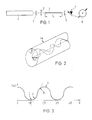
- the optical waveguide for measuring minimal expansions consists in that a polarization-maintaining, birefringent monomode optical fiber 4 is used as the optical fiber.
- This has, for example, an elliptical jacket around the round core, which causes permanent anisotropic mechanical tension.
- the FO 4 is combined with an upstream polarizer 2 and a coupling 3 and with a downstream analyzer 5 to form the FO phase sensor 6. This is preceded by a light transmitter 1, and a light receiver 7 and an electronic evaluation device 11 are connected downstream, fiber optic cables or cables 12 being used as connections.
- a laser or a laser diode is used as the transmitter 1, and a photodiode is used as the receiver 7.
- a computer 9 is installed in the evaluation device 11 on the receiver side and a controller 10 for the transmitter is installed on the transmitter side.
- the mode of operation of the fiber Explain the phase sensor as follows:
- the optical strain sensor works with a special fiber, namely with a polarization-maintaining single-mode fiber.
- an elliptical cladding was applied around the round core (the optical fiber), which causes permanent anisotropic (direction-dependent) mechanical tension.
- the optical waveguide becomes birefringent, ie an incident light wave is split into two partial waves.
- the main axes of the ellipse are at the same time the optical axes (perpendicular to the fiber optic axis, spatially fixed) with the refractive indices n o and n ao.
- Optical anisotropy and birefringence mean that the speed of light propagation depends in a characteristic way on the refractive index of the glass.
- the optical axes identify the polarization directions for which the refractive index difference n o - n ao becomes maximum.
- Linearly polarized light is shifted by the phase difference ⁇ as it passes through this optical fiber.
- the propagation of linearly polarized light in the birefringent optical fiber with the aforementioned axis position can be described in such a way that the incident wave is represented by superimposing two waves whose polarization directions correspond to the optical axes. After passing through the FO, the two waves are again superimposed, taking into account the phase difference ⁇ .
- the change in length of the optical fiber can be determined directly from the phase difference change in the light coupled into the optical fiber.
- the measurements of minimal strains are to be carried out in such a way that linearly polarized light is coupled into the polarization-maintaining and also birefringent single-mode optical fiber 4, which is shifted by the phase difference ⁇ when passing through the optical fiber, and which occurs when the optical fiber changes in length
- This fiber optic sensor is therefore particularly suitable as a sensor for measuring low strains, such as deflections of support or support elements.
- a change in length l of approximately 5 .mu.m with a measuring length l o 500 mm was sufficient to pass through the measuring range CD.
- a strain measurement with a display accuracy ⁇ l / l o by 10 ⁇ 6 is possible.
- the measuring speed only depends on the downstream electronics.
- the measuring range limited in the first application can be doubled if the measuring light is split into three channels using a grating. Then it is possible to determine the phase difference ⁇ modulo 2 ⁇ (module of congruence) with some arithmetic with similar accuracy. The interval 2 ⁇ can then also be exceeded, in particular in the case of dynamic processes.
- the measuring speed is of course reduced, but by detecting the number of phase shifts by 2 ⁇ in both directions, ie with the correct sign, larger changes in length can also be determined by an electronic counting process.
- the sensor concept according to the invention offers an excellent combination of high sensitivity and a large measuring range.
- the field of application of the fiber optic phase sensor includes the integral monitoring of metal and fiber composite constructions for critical deformations and structural damage.
- the fiber optic sensor is mechanically and permanently connected to the component to be monitored.
- embedding in the laminate is also possible.
- machine parts or bridge structures can be monitored for deflection, so that the dangers of operational failure are reduced.
- FIG. 5 shows how several fiber optic phase sensors 6 are arranged in the zones of an aircraft at risk of breakage, for example at different points in the tail unit 13, and how fiber optic cables 12 are connected from there to the optoelectronic transmitter 1 and receiver 7 arranged in the control room and the evaluation device 11 are guided.
Landscapes
- Physics & Mathematics (AREA)
- General Physics & Mathematics (AREA)
- Chemical & Material Sciences (AREA)
- Analytical Chemistry (AREA)
- Length Measuring Devices By Optical Means (AREA)
- Light Guides In General And Applications Therefor (AREA)
Applications Claiming Priority (2)
| Application Number | Priority Date | Filing Date | Title |
|---|---|---|---|
| DE19863638345 DE3638345A1 (de) | 1986-11-10 | 1986-11-10 | Einrichtung und verwendung eines lichtwellenleiter-sensors fuer minimale dehnungen |
| DE3638345 | 1986-11-10 |
Publications (3)
| Publication Number | Publication Date |
|---|---|
| EP0267381A2 true EP0267381A2 (fr) | 1988-05-18 |
| EP0267381A3 EP0267381A3 (en) | 1990-05-02 |
| EP0267381B1 EP0267381B1 (fr) | 1991-06-26 |
Family
ID=6313611
Family Applications (1)
| Application Number | Title | Priority Date | Filing Date |
|---|---|---|---|
| EP87112646A Expired - Lifetime EP0267381B1 (fr) | 1986-11-10 | 1987-08-29 | Dispositif et utilisation d'un capteur à fibres optiques pour la mesure d'allongements minimaux |
Country Status (3)
| Country | Link |
|---|---|
| US (1) | US4900920A (fr) |
| EP (1) | EP0267381B1 (fr) |
| DE (2) | DE3638345A1 (fr) |
Cited By (2)
| Publication number | Priority date | Publication date | Assignee | Title |
|---|---|---|---|---|
| FR2707754A1 (fr) * | 1993-07-12 | 1995-01-20 | Aerospatiale | Structure embarquée sur véhicule spatial, ayant des capteurs dimensionnels intégrés. |
| DE10004384A1 (de) * | 2000-02-02 | 2001-08-16 | Daimler Chrysler Ag | Anordnung und Verfahren zur Erfassung von Dehnungen und Temperaturen und deren Veränderungen einer auf einem Träger applizierten Deckschicht |
Families Citing this family (20)
| Publication number | Priority date | Publication date | Assignee | Title |
|---|---|---|---|---|
| US5182449A (en) * | 1990-02-06 | 1993-01-26 | The Boeing Corporation | System and method for structural monitoring using optical imaging of fiber sensors |
| DE4115370A1 (de) * | 1991-05-10 | 1992-11-26 | Asea Brown Boveri | Faseroptischer sensor |
| JP3065435B2 (ja) * | 1992-07-31 | 2000-07-17 | 浜松ホトニクス株式会社 | 光ファイバ部品の特性測定装置 |
| DE4344856A1 (de) * | 1993-12-29 | 1995-07-06 | Abb Research Ltd | Faseroptischer Transmissionssensor mit Modulator |
| AUPM547194A0 (en) * | 1994-05-06 | 1994-06-02 | University Of Sydney, The | Variable property light transmitting device |
| NO303470B1 (no) * | 1994-12-16 | 1998-07-13 | Safety One As | FremgangsmÕte og system til kontinuerlig og global overvÕking av dynamiske belastninger |
| DE19540335A1 (de) * | 1995-10-28 | 1997-04-30 | Kloeckner Moeller Gmbh | Einspeisekasten |
| DE19705889C2 (de) * | 1997-02-15 | 1999-12-09 | Daimler Chrysler Ag | Drehwinkelsensor |
| DE19902783C2 (de) * | 1999-01-25 | 2002-11-07 | Ettemeyer Ag | Meßeinheit |
| US6542304B2 (en) * | 1999-05-17 | 2003-04-01 | Toolz, Ltd. | Laser beam device with apertured reflective element |
| US6741189B1 (en) * | 1999-10-06 | 2004-05-25 | Microsoft Corporation | Keypad having optical waveguides |
| US20040129868A1 (en) * | 2003-01-08 | 2004-07-08 | Siemens Vdo Automotive Corporation. | Deflection sensor |
| US7578199B2 (en) * | 2003-08-27 | 2009-08-25 | Airbus Uk Limited | Apparatus and method suitable for measuring the displacement or load on an aircraft component |
| US7792614B2 (en) * | 2003-08-27 | 2010-09-07 | Airbus Uk Limited | Apparatus and method suitable for measuring the global displacement or load on an aircraft component |
| EP1664707A1 (fr) * | 2003-08-27 | 2006-06-07 | Airbus UK Limited | Mesure de charge,deplacement sur une partie d'avion avec un faisceau a micro-ondes |
| DE102010005665A1 (de) | 2010-01-26 | 2011-07-28 | Dr. Ing. h.c. F. Porsche Aktiengesellschaft, 70435 | Torsionsmesssystem und Verfahren zur Torsionsmessung |
| US8534132B1 (en) | 2010-11-19 | 2013-09-17 | Charles L. Purdy | Method for measuring tension in an anchored rod at an accessible end |
| DE102014002109A1 (de) * | 2014-02-15 | 2015-08-20 | Audi Ag | Bauelement, Bauteilanordnung und Verfahren zur Verformungsdetektion eines Bauelementes |
| DE102016125730A1 (de) | 2016-12-27 | 2018-06-28 | fos4X GmbH | Vorrichtung und Verfahren zum Messen der Torsion eines Messobjekts |
| DE102019219918A1 (de) * | 2019-12-17 | 2021-06-17 | Peri Gmbh | Schalungsplatte für eine Schalungsvorrichtung |
Family Cites Families (12)
| Publication number | Priority date | Publication date | Assignee | Title |
|---|---|---|---|---|
| DE2602691A1 (de) * | 1976-01-24 | 1977-07-28 | Caspers Friedhelm | Vorrichung zur messung kleiner laengenaenderungen basierend auf der phasendrehung in optischen dielektrischen leitungen |
| DE2816682A1 (de) * | 1978-04-18 | 1979-12-20 | Max Planck Gesellschaft | Anordnung zur erfassung des einflusses physikalischer groessen auf die laenge eines weges |
| US4420251A (en) * | 1980-05-05 | 1983-12-13 | Rockwell International Corporation | Optical deformation sensor |
| US4659923A (en) * | 1981-03-09 | 1987-04-21 | Polaroid Corporation | Fiber optic interferometer transducer |
| DE8212823U1 (de) * | 1982-05-04 | 1982-08-19 | Felten & Guilleaume Energietechnik GmbH, 5000 Köln | Lichtwellenleiter-sensor fuer kleine radioaktive strahlendosen |
| US4495411A (en) * | 1982-10-27 | 1985-01-22 | The United States Of America As Represented By The Secretary Of The Navy | Fiber optic sensors operating at DC |
| DE3305234C2 (de) * | 1983-02-16 | 1986-02-27 | Felten & Guilleaume Energietechnik GmbH, 5000 Köln | Zugfester Draht aus einer faserverstärkten Harzstruktur mit mindestens einem darin eingeschlossenen Lichtwellenleiter |
| DE3311524C2 (de) * | 1983-03-30 | 1985-11-14 | Licentia Patent-Verwaltungs-Gmbh, 6000 Frankfurt | Faseroptischer Sensor für Kraft- und Druckmessungen sowie für Überwachungs- und Schutzzwecke |
| DE3415855A1 (de) * | 1984-04-28 | 1985-11-07 | Licentia Patent-Verwaltungs-Gmbh, 6000 Frankfurt | Faseroptische messeinrichtung zur erfassung einer an einem bauelement auftretenden zugspannung oder biegung |
| US4515473A (en) * | 1984-09-13 | 1985-05-07 | Geo-Centers, Inc. | Photoelastic stress sensor signal processor |
| DE3526966A1 (de) * | 1984-11-14 | 1986-05-15 | Felten & Guilleaume Energietechnik GmbH, 5000 Köln | Lichtwellenleiter-sensor fuer zugkraefte und verfahren zu seiner herstellung |
| US4671659A (en) * | 1985-11-08 | 1987-06-09 | Martin Marietta Corporation | Fiber optic displacement sensor |
-
1986
- 1986-11-10 DE DE19863638345 patent/DE3638345A1/de not_active Withdrawn
-
1987
- 1987-08-29 EP EP87112646A patent/EP0267381B1/fr not_active Expired - Lifetime
- 1987-08-29 DE DE8787112646T patent/DE3771031D1/de not_active Expired - Lifetime
- 1987-11-02 US US07/116,032 patent/US4900920A/en not_active Expired - Fee Related
Cited By (4)
| Publication number | Priority date | Publication date | Assignee | Title |
|---|---|---|---|---|
| FR2707754A1 (fr) * | 1993-07-12 | 1995-01-20 | Aerospatiale | Structure embarquée sur véhicule spatial, ayant des capteurs dimensionnels intégrés. |
| DE10004384A1 (de) * | 2000-02-02 | 2001-08-16 | Daimler Chrysler Ag | Anordnung und Verfahren zur Erfassung von Dehnungen und Temperaturen und deren Veränderungen einer auf einem Träger applizierten Deckschicht |
| DE10004384C2 (de) * | 2000-02-02 | 2003-04-03 | Daimler Chrysler Ag | Anordnung und Verfahren zur Erfassung von Dehnungen und Temperaturen und deren Veränderungen einer auf einem Träger, insbesondere einem aus Metall, Kunststoff oder Keramik bestehenden Träger, applizierten Deckschicht |
| US6587188B2 (en) | 2000-02-02 | 2003-07-01 | Airbus Deutschland Gmbh | Method and sensor arrangement for measuring temperature and strain using an optical fiber embedded in a cover layer on a substrate |
Also Published As
| Publication number | Publication date |
|---|---|
| EP0267381B1 (fr) | 1991-06-26 |
| DE3638345A1 (de) | 1988-05-19 |
| DE3771031D1 (de) | 1991-08-01 |
| EP0267381A3 (en) | 1990-05-02 |
| US4900920A (en) | 1990-02-13 |
Similar Documents
| Publication | Publication Date | Title |
|---|---|---|
| EP0267381A2 (fr) | Dispositif et utilisation d'un capteur à fibres optiques pour la mesure d'allongements minimaux | |
| EP0153997B1 (fr) | Méthode pour la mesure de la force à l'aide de la réfraction double induit par tension dans un guide de lumière monomode et dispositif de mesure pour la mise en oeuvre de la méthode | |
| DE69131214T2 (de) | Stromsonde mit Faraday-Effekt | |
| EP0856737B1 (fr) | Capteur de courant magnéto optique | |
| EP0430060B1 (fr) | Ampèremètre à fibre optique | |
| EP0340577B1 (fr) | Procédé et dispositif pour la détermination de l'indice de réfractions d'une substance | |
| DE60216752T2 (de) | Faseroptische rückstreu-polarimetrie | |
| EP0611974B1 (fr) | Tête de sonde pour dispositif de mesure de courant à fibre optique | |
| DE19703128A9 (de) | Magnetooptischer Stromsensor | |
| DE2703319A1 (de) | Opto-elektrische abzweigungsvorrichtung und verfahren zu ihrer herstellung | |
| CH644209A5 (de) | Faseroptische anordnung zur messung der staerke eines elektrischen stromes und verfahren zur herstellung einer solchen anordnung. | |
| EP1899700A1 (fr) | Jauge extensometrique optique | |
| EP0361588A1 (fr) | Capteur à fibre optique | |
| DE69414750T2 (de) | Photodetektor und Verfahren zum Empfangen optischer Signale unbekannter Polarisation | |
| DE69217246T2 (de) | Doppelbrechender temperaturfühler | |
| EP1101124B1 (fr) | Detecteur polarimetrique pour detection optique d'une grandeur de mesure et utilisation dudit detecteur polarimetrique | |
| DE102011084579B4 (de) | Vorrichtung und Verfahren zur Überwachung des Zustands einer Klebverbindung | |
| EP3019826B1 (fr) | Coupleur optique intégré et système fibre-optique ayant un tel coupleur optique intégré | |
| DE3031961C2 (de) | Interferometrische Einrichtung zur Messung physikalischer Größen | |
| EP0327688A2 (fr) | Procédé de mesure en continu de l'atténuation de capteurs à fibres optiques accessibles d'un seul côté | |
| DE102017131388B4 (de) | Faseroptischer Torsionswinkelsensor und Verfahren zum Erfassen eines Torsionswinkels | |
| DE102017201523A1 (de) | Faseroptische Erfassungseinrichtung sowie Verfahren zum Betreiben einer solchen faseroptischen Erfassungseinrichtung | |
| EP1896813A2 (fr) | Jauge extensometrique optique | |
| DE3325945A1 (de) | Faseroptischer sensor und eine diesen enthaltende sensoreinrichtung | |
| DE3822512C2 (fr) |
Legal Events
| Date | Code | Title | Description |
|---|---|---|---|
| PUAI | Public reference made under article 153(3) epc to a published international application that has entered the european phase |
Free format text: ORIGINAL CODE: 0009012 |
|
| AK | Designated contracting states |
Kind code of ref document: A2 Designated state(s): BE CH DE FR GB IT LI NL SE |
|
| PUAL | Search report despatched |
Free format text: ORIGINAL CODE: 0009013 |
|
| 17P | Request for examination filed |
Effective date: 19900219 |
|
| AK | Designated contracting states |
Kind code of ref document: A3 Designated state(s): BE CH DE FR GB IT LI NL SE |
|
| 17Q | First examination report despatched |
Effective date: 19900710 |
|
| GRAA | (expected) grant |
Free format text: ORIGINAL CODE: 0009210 |
|
| AK | Designated contracting states |
Kind code of ref document: B1 Designated state(s): BE CH DE FR GB IT LI NL SE |
|
| ITF | It: translation for a ep patent filed | ||
| ET | Fr: translation filed | ||
| REF | Corresponds to: |
Ref document number: 3771031 Country of ref document: DE Date of ref document: 19910801 |
|
| GBT | Gb: translation of ep patent filed (gb section 77(6)(a)/1977) | ||
| PGFP | Annual fee paid to national office [announced via postgrant information from national office to epo] |
Ref country code: BE Payment date: 19920428 Year of fee payment: 6 |
|
| PLBE | No opposition filed within time limit |
Free format text: ORIGINAL CODE: 0009261 |
|
| STAA | Information on the status of an ep patent application or granted ep patent |
Free format text: STATUS: NO OPPOSITION FILED WITHIN TIME LIMIT |
|
| 26N | No opposition filed | ||
| PGFP | Annual fee paid to national office [announced via postgrant information from national office to epo] |
Ref country code: SE Payment date: 19920708 Year of fee payment: 6 |
|
| PGFP | Annual fee paid to national office [announced via postgrant information from national office to epo] |
Ref country code: GB Payment date: 19920818 Year of fee payment: 6 |
|
| PGFP | Annual fee paid to national office [announced via postgrant information from national office to epo] |
Ref country code: FR Payment date: 19920827 Year of fee payment: 6 |
|
| PGFP | Annual fee paid to national office [announced via postgrant information from national office to epo] |
Ref country code: NL Payment date: 19920831 Year of fee payment: 6 |
|
| PGFP | Annual fee paid to national office [announced via postgrant information from national office to epo] |
Ref country code: CH Payment date: 19920902 Year of fee payment: 6 |
|
| PG25 | Lapsed in a contracting state [announced via postgrant information from national office to epo] |
Ref country code: GB Effective date: 19930829 |
|
| PG25 | Lapsed in a contracting state [announced via postgrant information from national office to epo] |
Ref country code: SE Effective date: 19930830 |
|
| PG25 | Lapsed in a contracting state [announced via postgrant information from national office to epo] |
Ref country code: LI Effective date: 19930831 Ref country code: CH Effective date: 19930831 Ref country code: BE Effective date: 19930831 |
|
| PGFP | Annual fee paid to national office [announced via postgrant information from national office to epo] |
Ref country code: DE Payment date: 19930831 Year of fee payment: 7 |
|
| BERE | Be: lapsed |
Owner name: FELTEN & GUILLEAUME ENERGIETECHNIK A.G. Effective date: 19930831 |
|
| PG25 | Lapsed in a contracting state [announced via postgrant information from national office to epo] |
Ref country code: NL Effective date: 19940301 |
|
| NLV4 | Nl: lapsed or anulled due to non-payment of the annual fee | ||
| GBPC | Gb: european patent ceased through non-payment of renewal fee |
Effective date: 19930829 |
|
| PG25 | Lapsed in a contracting state [announced via postgrant information from national office to epo] |
Ref country code: FR Effective date: 19940429 |
|
| REG | Reference to a national code |
Ref country code: CH Ref legal event code: PL |
|
| REG | Reference to a national code |
Ref country code: FR Ref legal event code: ST |
|
| EUG | Se: european patent has lapsed |
Ref document number: 87112646.2 Effective date: 19940310 |
|
| PG25 | Lapsed in a contracting state [announced via postgrant information from national office to epo] |
Ref country code: DE Effective date: 19950801 |
|
| PG25 | Lapsed in a contracting state [announced via postgrant information from national office to epo] |
Ref country code: IT Free format text: LAPSE BECAUSE OF NON-PAYMENT OF DUE FEES Effective date: 20050829 |