EP0267407A1 - Sicherungseinrichtung für einen Zünder eines Gefechtskopfes - Google Patents
Sicherungseinrichtung für einen Zünder eines Gefechtskopfes Download PDFInfo
- Publication number
- EP0267407A1 EP0267407A1 EP87114311A EP87114311A EP0267407A1 EP 0267407 A1 EP0267407 A1 EP 0267407A1 EP 87114311 A EP87114311 A EP 87114311A EP 87114311 A EP87114311 A EP 87114311A EP 0267407 A1 EP0267407 A1 EP 0267407A1
- Authority
- EP
- European Patent Office
- Prior art keywords
- rotor
- ignition device
- built
- collar
- securing
- Prior art date
- Legal status (The legal status is an assumption and is not a legal conclusion. Google has not performed a legal analysis and makes no representation as to the accuracy of the status listed.)
- Granted
Links
- 238000009434 installation Methods 0.000 claims abstract description 13
- 230000008878 coupling Effects 0.000 claims abstract description 6
- 238000010168 coupling process Methods 0.000 claims abstract description 6
- 238000005859 coupling reaction Methods 0.000 claims abstract description 6
- 230000007704 transition Effects 0.000 claims abstract description 3
- 230000000903 blocking effect Effects 0.000 claims description 5
- 230000006835 compression Effects 0.000 description 1
- 238000007906 compression Methods 0.000 description 1
- 230000002349 favourable effect Effects 0.000 description 1
Images

Classifications
-
- F—MECHANICAL ENGINEERING; LIGHTING; HEATING; WEAPONS; BLASTING
- F42—AMMUNITION; BLASTING
- F42C—AMMUNITION FUZES; ARMING OR SAFETY MEANS THEREFOR
- F42C15/00—Arming-means in fuzes; Safety means for preventing premature detonation of fuzes or charges
- F42C15/18—Arming-means in fuzes; Safety means for preventing premature detonation of fuzes or charges wherein a carrier for an element of the pyrotechnic or explosive train is moved
- F42C15/188—Arming-means in fuzes; Safety means for preventing premature detonation of fuzes or charges wherein a carrier for an element of the pyrotechnic or explosive train is moved using a rotatable carrier
-
- F—MECHANICAL ENGINEERING; LIGHTING; HEATING; WEAPONS; BLASTING
- F42—AMMUNITION; BLASTING
- F42C—AMMUNITION FUZES; ARMING OR SAFETY MEANS THEREFOR
- F42C19/00—Details of fuzes
Definitions
- the invention relates to an ignition device which is provided with a rotor which passes from its securing to its arming position by means of unlocking and which can be installed in an ammunition.
- Such an ignition device is described for example in DE-GM 81 19 466.8.
- Such an ignition device is to be installed in a warhead, for example. Taking strict safety requirements into account, it cannot be completely ruled out that the rotor of the ignition device is no longer in a safe state even before it is installed in the warhead, but has already entered its focus.
- the object of the invention is to exclude the installation of the ignition device by mechanical means when the rotor is in the arming position before installation, but these means must not prevent the rotor from moving from its securing to its arming position when the ignition device is installed.
- the above object is achieved in that the ignition device has a built-in securing element which, in one position (blocking position), prevents the ignition device from being assigned to the ammunition in the correct position and which, in its other position (installation position), permits this assignment, and that between the rotor and the Installation fuse link one Coupling point is formed, via which the rotor in focus blocks the built-in securing element in the blocking position and via which the rotor in safe position releases the built-in safety element for the transition to the installed position and which releases the rotor in the installed position of the built-in safety element.
- the built-in fuse link must be operated manually. If it is blocked, the rotor must first be secured.
- An ignition device has a carrier base (1).
- a rotor (3) rotatable about an axis (2) is mounted on this.
- the rotor (3) has a bore (4). These is in the securing of the rotor (3) shown in Figure 2 outside the ignition chain of the ignition device, not shown.
- the rotor (3) is secured with known securing means. When the securing means are released, the rotor (3) swivels in the direction of the arrow (P) (see FIG. 2) until the bore (4) is in line with the ignition chain of the ignition device.
- a built-in securing element (5) formed by a pin is arranged on the carrier base (1).
- the built-in securing element (5) is guided on the one hand on a bushing (6) screwed into the support base (1) and on the other hand on a bearing plate (7) which is connected to the support base (1) by a bolt (8).
- the built-in securing element (5) can be moved parallel to the axis (2). It has a locking extension (9) and a collar (10). A compression spring (11) presses the built-in securing element (5) so that its locking extension (9) projects beyond the support base (1) (FIG. 1).
- a part-circular recess (12) is provided on the outer circumference of the rotor (3). This merges into an annular groove (13) extending on the circumference of the rotor (3).
- the recess (12) and the annular groove (13) of the rotor (3) on the one hand and the collar (10) of the built-in securing element (5) on the other hand form a coupling point between these two parts.
- the collar (10) lies below the recess (12). If the rotor (3) is secure, its recess (12) is aligned with the collar (10).
- the ignition device is to be installed in a warhead, then its support base (1) is placed on a corresponding surface of the warhead. in the As a rule, when the rotor (3) is in the safe position, the installation securing element (5) is pushed into the ignition device against the force of the spring (11) via the locking extension (9). The collar (10) slides into the recess (12). The locking extension (9) therefore does not hinder the installation of the ignition device.
- the collar (10) lies at the level of the annular groove (13). If the rotor (3) is then unlocked later, it swivels into focus. The collar (10) does not hinder this, since the annular groove (13) moves freely with respect to the collar (10).
- the blocking extension (9) does not move back when the carrier base (1) is placed on the corresponding surface of the warhead. Because the collar (10) then strikes the edge (14) of the rotor (3). Installation of the ignition device is therefore not possible.
Landscapes
- Engineering & Computer Science (AREA)
- General Engineering & Computer Science (AREA)
- Ignition Installations For Internal Combustion Engines (AREA)
- Automotive Seat Belt Assembly (AREA)
- Meat, Egg Or Seafood Products (AREA)
- Fuses (AREA)
Abstract
Description
- Die Erfindung betrifft eine Zündeinrichtung, die mit einem Rotor versehen ist, der durch Entsichern aus seiner Sicherstellung in seine Scharfstellung übergeht, und die in eine Munition einbaubar ist.
- Eine derartige Zündeinrichtung ist beispielsweise in dem DE-GM 81 19 466.8 beschrieben.
- Eine solche Zündeinrichtung ist beispielsweise in einen Gefechtskopf einzubauen. Unter Berücksichtigung strenger Sicherheitsanforderungen ist nicht gänzlich auszuschließen, daß der Rotor der Zündeinrichtung schon vor deren Einbau in den Gefechtskopf nicht mehr in Sicherstellung steht, sondern bereits in seine Scharfstellung übergegangen ist.
- Aufgabe der Erfindung ist es, die Einbaubarkeit der Zündeinrichtung durch mechanische Mittel auszuschließen, wenn der Rotor vor Einbau in Scharfstellung steht, wobei diese Mittel jedoch nicht verhindern dürfen, daß bei eingebauter Zündeinrichtung der Rotor aus seiner Sicherstellung in seine Scharfstellung übergehen kann.
- Erfindungsgemäß ist obige Aufgabe dadurch gelöst, daß die Zündeinrichtung ein Einbausicherungsglied aufweist, das in seiner einen Stellung (Sperrstellung) die einbaurichtige Zuordnung der Zündeinrichtung zur Munition verhindert und das in seiner anderen Stellung (Einbaustellung) diese Zuordnung erlaubt, und daß zwischen dem Rotor und dem Einbausicherungsglied eine Koppelstelle ausgebildet ist, über die der in Scharfstellung stehende Rotor das Einbausicherungsglied in Sperrstellung blockiert und über die der in Sicherstellung stehende Rotor das Einbausicherungsglied zum Übergang in die Einbaustellung freigibt und die in der Einbaustellung des Einbausicherungsgliedes den Rotor freigibt.
- Dadurch ist zwangsweise erreicht, daß eine Zündeinrichtung mit in Scharfstellung stehendem Rotor nicht in die Munition eingebaut werden kann. Nur wenn der Rotor in Sicherstellung steht, läßt sich die Zündeinrichtung an der Munition befestigen.
- Günstig ist auch, daß an der Zündeinrichtung schon vor dem Einbau geprüft werden kann, ob der Rotor in Sicherstellung steht. Es ist hierfür das Einbausicherungsglied manuell zu betätigen. Ist es blockiert, dann muß der Rotor zunächst in Sicherstellung gestellt werden.
- Vorteilhafte Ausgestaltungen der Erfindung ergeben sich aus den Unteransprüchen und der folgenden Beschreibung eines Ausführungsbeispiels. In der Zeichnung zeigen:
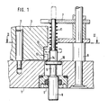
- Figur 1 einen Teilschnitt einer Zündeinrichtung längs der Linie I-I nach Figur 2,
- Figur 2 einen Schnitt längs der Linie II-II nach Figur 1
und - Figur 3 eine Ansicht des Rotors in Richtung des Pfeiles III in Figur 2.
- Eine Zündeinrichtung weist einen Trägerboden(1) auf. An diesem ist ein um eine Achse(2) drehbarer Rotor(3) gelagert. Der Rotor(3) weist eine Bohrung(4) auf. Diese liegt bei der in Figur 2 dargestellten Sicherstellung des Rotors(3) außerhalb der nicht näher dargestellten Zündkette der Zündeinrichtung. Der Rotor(3) ist in seiner Sicherstellung mit bekannten Sicherungsmitteln gehalten. Bei Freigabe der Sicherungsmittel schwenkt der Rotor(3) in Richtung des Pfeiles(P) (vgl. Figur 2), bis die Bohrung(4) in der Linie der Zündkette der Zündeinrichtung steht.
- Am Trägerboden(1) ist ein von einem Stift gebildetes Einbausicherungsglied(5) angeordnet. Das Einbausicherungsglied(5) ist einerseits an einer in den Trägerboden(1) eingeschraubten Buchse(6) und andererseits an einer Lagerplatte(7) geführt, die über einen Bolzen(8) mit dem Trägerboden(1) verbunden ist.
- Das Einbausicherungsglied(5) ist parallel zur Achse(2) verschieblich. Es weist einen Sperrfortsatz(9) und einen Bund(10) auf. Eine Druckfeder(11) drückt das Einbausicherungsglied(5) so, daß sein Sperrfortsatz(9) den Trägerboden(1) überragt (Figur 1).
- An dem Außenumfang des Rotors(3) ist eine teilkreisförmige Ausn ehmung(12) vorgesehen. Diese geht in eine sich am Umfang des Rotors(3) erstreckende Ringnut(13) über. Die Ausnehmung(12) und die Ringnut(13) des Rotors(3) einerseits und der Bund(10) des Einbausicherungsglieds(5) andererseits bilden eine Koppelstelle zwischen diesen beiden Teilen.
- In der in Figur 1 dargestellten Stellung des Einbausicherungsgliedes(5) liegt der Bund(10) unterhalb der Ausnehmung(12). Steht der Rotor(3) in Sicherstellung, dann fluchtet dessen Ausnehmung(12) mit dem Bund(10).
- Soll die Zündeinrichtung in einen Gefechtskopf eingebaut werden, dann wird sie mit ihrem Trägerboden(1) auf eine entsprechende Fläche des Gefechtskopfes aufgesetzt. Im Regelfall, wenn der Rotor(3) in Sicherstellung steht, wird dadurch über den Sperrfortsatz(9) das Einbausicherungsglied(5) gegen die Kraft der Feder(11) in die Zündeinrichtung geschoben. Der Bund(10) schiebt sich dabei in die Ausnehmung(12). Der Sperrfortsatz(9) behindert also den Einbau der Zündeinrichtung nicht.
- Bei eingebauter Zündeinrichtung liegt der Bund(10) in Höhe der Ringnut(13). Wird dann später der Rotor(3) entsichert, dann schwenkt er in Scharfstellung. Der Bund(10) behindert dies nicht, da sich die Ringnut(13) frei gegenüber dem Bund(10) bewegt.
- Steht der Rotor(3) in Scharfstellung, wenn die Zündeinrichtung eingebaut werden soll, dann schiebt sich der Sperrfortsatz(9) nicht zurück, wenn der Trägerboden(1) auf die entsprechende Fläche des Gefechtskopfs aufgesetzt wird. Denn der Bund(10) schlägt dann an dem Rand(14) des Rotors(3) an. Ein Einbau der Zündeinrichtung ist damit nicht möglich.
Claims (5)
dadurch gekennzeichnet,
daß die Zündeinrichtung ein Einbausicherungsglied(5) aufweist, das in seiner einen Stellung (Sperrstellung) die einbaurichtige Zuordnung der Zündeinrichtung zur Munition verhindert und das in seiner anderen Stellung (Einbaustellung) diese Zuordnung erlaubt, und daß zwischen dem Rotor(3) und dem Einbausicherungsglied(5) eine Koppelstelle(10,12,13) ausgebildet ist, über die der in Scharfstellung stehende Rotor(3) das Einbausicherungsglied(5) in Sperrstellung blockiert und über die der in Sicherstellung stehende Rotor(3) das Einbausicherungsglied(5) zum Übergang in die Einbaustellung freigibt und die in der Einbaustellung des Einbausicherungsgliedes(5) den Rotor(3) freigibt.
dadurch gekennzeichnet,
daß das Einbausicherungsglied(5) ein parallel zur Drehachse(2) des Rotors(3) verschieblicher Stift ist.
dadurch gekennzeichnet,
daß das Einbausicherungsglied(5) einen einen Trägerboden(1) der Zündeinrichtung federbelastet überragenden Sperrfortsatz(9) aufweist.
dadurch gekennzeichnet,
daß die Koppelstelle von einem Bund(10) des Einbausicherungsgliedes(5) und einer teilkreisförmigen, drehachsparallelen und zum Bund(10) offenen Ausnehmung(12) des Rotors(3) gebildet ist, die in eine Ringnut(13) übergeht, in die der Bund(10) eingreift, wenn der Rotor(3) in Sicherstellung steht.
dadurch gekennzeichnet,
daß in Sicherstellung des Rotors(3) der Bund(10) in der Ausnehmung(12) bis zur Ringnut(13) einschiebbar ist und daß in Scharfstellung des Rotors(3) der Bund(10) außerhalb der Ausnehmung(12) am Rotor(3) anschlägt.
Applications Claiming Priority (2)
| Application Number | Priority Date | Filing Date | Title |
|---|---|---|---|
| DE19863635084 DE3635084A1 (de) | 1986-10-15 | 1986-10-15 | Zuendeinrichtung |
| DE3635084 | 1986-10-15 |
Publications (2)
| Publication Number | Publication Date |
|---|---|
| EP0267407A1 true EP0267407A1 (de) | 1988-05-18 |
| EP0267407B1 EP0267407B1 (de) | 1991-01-16 |
Family
ID=6311771
Family Applications (1)
| Application Number | Title | Priority Date | Filing Date |
|---|---|---|---|
| EP87114311A Expired - Lifetime EP0267407B1 (de) | 1986-10-15 | 1987-10-01 | Sicherungseinrichtung für einen Zünder eines Gefechtskopfes |
Country Status (5)
| Country | Link |
|---|---|
| US (1) | US4790246A (de) |
| EP (1) | EP0267407B1 (de) |
| DE (2) | DE3635084A1 (de) |
| DK (1) | DK163746C (de) |
| NO (1) | NO166057C (de) |
Families Citing this family (2)
| Publication number | Priority date | Publication date | Assignee | Title |
|---|---|---|---|---|
| NO891579L (no) * | 1988-05-16 | 1989-11-17 | Oerlikon Buehrle Ag | Blindgjengerinnlegg for en prosjektiltenner. |
| US5052303A (en) * | 1990-04-30 | 1991-10-01 | Motorola, Inc. | Interlocked release mechanism with timed, sequential release steps |
Citations (3)
| Publication number | Priority date | Publication date | Assignee | Title |
|---|---|---|---|---|
| DE2640782A1 (de) * | 1976-09-10 | 1978-03-16 | Junghans Gmbh Geb | Sicherungseinrichtung an zuendern |
| DE3015424A1 (de) * | 1980-04-22 | 1981-10-29 | Diehl GmbH & Co, 8500 Nürnberg | Sicherungsvorrichtung fuer zuender von drallosen oder drallarmen geschossen |
| FR2543288A1 (fr) * | 1983-03-23 | 1984-09-28 | Luchaire Sa | Fusee de culot pour bombe |
Family Cites Families (5)
| Publication number | Priority date | Publication date | Assignee | Title |
|---|---|---|---|---|
| US3763785A (en) * | 1972-03-20 | 1973-10-09 | Us Navy | Mal-assembly feature for explosive train fuzes |
| US3973501A (en) * | 1973-01-11 | 1976-08-10 | The United States Of America As Represented By The Secretary Of The Navy | Fuze with dual safe positions and armed-safe indicator |
| CH600294A5 (de) * | 1976-04-06 | 1978-06-15 | Mefina Sa | |
| DE3107110C2 (de) * | 1981-02-26 | 1984-03-29 | Gebrüder Junghans GmbH, 7230 Schramberg | Sicherungsvorrichtung für Zünder von Drallgeschossen |
| DE8119466U1 (de) * | 1981-07-03 | 1982-09-16 | Diehl GmbH & Co, 8500 Nürnberg | Sicherungseinrichtung fuer geschosszuender |
-
1986
- 1986-10-15 DE DE19863635084 patent/DE3635084A1/de not_active Withdrawn
-
1987
- 1987-09-10 NO NO873779A patent/NO166057C/no unknown
- 1987-10-01 DE DE8787114311T patent/DE3767444D1/de not_active Expired - Fee Related
- 1987-10-01 US US07/103,496 patent/US4790246A/en not_active Expired - Fee Related
- 1987-10-01 EP EP87114311A patent/EP0267407B1/de not_active Expired - Lifetime
- 1987-10-13 DK DK535187A patent/DK163746C/da not_active IP Right Cessation
Patent Citations (3)
| Publication number | Priority date | Publication date | Assignee | Title |
|---|---|---|---|---|
| DE2640782A1 (de) * | 1976-09-10 | 1978-03-16 | Junghans Gmbh Geb | Sicherungseinrichtung an zuendern |
| DE3015424A1 (de) * | 1980-04-22 | 1981-10-29 | Diehl GmbH & Co, 8500 Nürnberg | Sicherungsvorrichtung fuer zuender von drallosen oder drallarmen geschossen |
| FR2543288A1 (fr) * | 1983-03-23 | 1984-09-28 | Luchaire Sa | Fusee de culot pour bombe |
Also Published As
| Publication number | Publication date |
|---|---|
| NO166057C (no) | 1991-05-22 |
| DK163746B (da) | 1992-03-30 |
| DK535187D0 (da) | 1987-10-13 |
| NO873779L (no) | 1988-04-18 |
| DE3767444D1 (de) | 1991-02-21 |
| DE3635084A1 (de) | 1988-04-21 |
| NO166057B (no) | 1991-02-11 |
| NO873779D0 (no) | 1987-09-10 |
| US4790246A (en) | 1988-12-13 |
| DK163746C (da) | 1992-08-31 |
| DK535187A (da) | 1988-04-16 |
| EP0267407B1 (de) | 1991-01-16 |
Similar Documents
| Publication | Publication Date | Title |
|---|---|---|
| DE69104464T2 (de) | Zylinderschloss. | |
| DE69417530T2 (de) | Gegen Einbruch widerstandsfähiges Zylinderschloss | |
| DE3107110C2 (de) | Sicherungsvorrichtung für Zünder von Drallgeschossen | |
| DE2753206C2 (de) | Magnetschlüssel betätigbare Kupplungseinrichtung für eine Drehhandhabe | |
| DE2754372A1 (de) | Lenkschloss fuer kraftfahrzeuge | |
| EP0026348B1 (de) | Mehrfach gesicherter Unterwasserzünder | |
| EP0194422B1 (de) | Vorrichtung zum Sichern einer Verbindung | |
| DE2750018A1 (de) | Sicherungsklappe fuer zuend- und leuchtspursaetze | |
| EP0267407A1 (de) | Sicherungseinrichtung für einen Zünder eines Gefechtskopfes | |
| DE2241608A1 (de) | Werkzeughalter | |
| DE3230633C2 (de) | Magnetschloß | |
| DE2728133A1 (de) | Bajonettverschluss | |
| DE3224630C2 (de) | Schließzylinder, insbesondere für Kraftfahrzeug-Lenkschlösser | |
| DE9007529U1 (de) | Multikaliber-Schußwaffe | |
| EP0415033A2 (de) | Energieführungskette | |
| DE3140792A1 (de) | "sicherungsvorrichtung fuer auf eine wickelwelle aufgerollte oeffnungsabschluesse" | |
| DE3018544C2 (de) | Kabelschloß | |
| DE3205153A1 (de) | Vorrichtung fuer einen zuender eines drallgeschosses | |
| DE2533435A1 (de) | Kreiselrotor-fesselvorrichtung | |
| DE3830376A1 (de) | Einrichtung zur befestigung von elektronischen modulen an einem basisteil | |
| DE7927845U1 (de) | Unterwasserzünder zum Zünden von Sprengladungen | |
| DE3435461C1 (de) | Sicherungsvorrichtung gegen ungewolltes Abrollen von Rolltoren o.dgl. | |
| EP1826340A1 (de) | Zylinderschloss mit Sperrscheiben | |
| DE2939711A1 (de) | Unterwasserzuender zum zuenden von sprengladungen | |
| DE1281875B (de) | Lenkschloss fuer Kraftfahrzeuge |
Legal Events
| Date | Code | Title | Description |
|---|---|---|---|
| PUAI | Public reference made under article 153(3) epc to a published international application that has entered the european phase |
Free format text: ORIGINAL CODE: 0009012 |
|
| AK | Designated contracting states |
Kind code of ref document: A1 Designated state(s): BE CH DE FR GB IT LI NL |
|
| 17P | Request for examination filed |
Effective date: 19880331 |
|
| 17Q | First examination report despatched |
Effective date: 19890417 |
|
| GRAA | (expected) grant |
Free format text: ORIGINAL CODE: 0009210 |
|
| AK | Designated contracting states |
Kind code of ref document: B1 Designated state(s): BE CH DE FR GB IT LI NL |
|
| REF | Corresponds to: |
Ref document number: 3767444 Country of ref document: DE Date of ref document: 19910221 |
|
| ITF | It: translation for a ep patent filed | ||
| ET | Fr: translation filed | ||
| GBT | Gb: translation of ep patent filed (gb section 77(6)(a)/1977) | ||
| PGFP | Annual fee paid to national office [announced via postgrant information from national office to epo] |
Ref country code: BE Payment date: 19910905 Year of fee payment: 5 |
|
| PGFP | Annual fee paid to national office [announced via postgrant information from national office to epo] |
Ref country code: NL Payment date: 19911031 Year of fee payment: 5 |
|
| PLBE | No opposition filed within time limit |
Free format text: ORIGINAL CODE: 0009261 |
|
| STAA | Information on the status of an ep patent application or granted ep patent |
Free format text: STATUS: NO OPPOSITION FILED WITHIN TIME LIMIT |
|
| 26N | No opposition filed | ||
| PGFP | Annual fee paid to national office [announced via postgrant information from national office to epo] |
Ref country code: CH Payment date: 19920907 Year of fee payment: 6 |
|
| PGFP | Annual fee paid to national office [announced via postgrant information from national office to epo] |
Ref country code: GB Payment date: 19920930 Year of fee payment: 6 Ref country code: FR Payment date: 19920930 Year of fee payment: 6 |
|
| PG25 | Lapsed in a contracting state [announced via postgrant information from national office to epo] |
Ref country code: BE Effective date: 19921031 |
|
| PGFP | Annual fee paid to national office [announced via postgrant information from national office to epo] |
Ref country code: DE Payment date: 19921217 Year of fee payment: 6 |
|
| BERE | Be: lapsed |
Owner name: GEBRUDER JUNGHANS G.M.B.H. Effective date: 19921031 |
|
| PG25 | Lapsed in a contracting state [announced via postgrant information from national office to epo] |
Ref country code: NL Effective date: 19930501 |
|
| NLV4 | Nl: lapsed or anulled due to non-payment of the annual fee | ||
| PG25 | Lapsed in a contracting state [announced via postgrant information from national office to epo] |
Ref country code: GB Effective date: 19931001 |
|
| PG25 | Lapsed in a contracting state [announced via postgrant information from national office to epo] |
Ref country code: CH Effective date: 19931031 Ref country code: LI Effective date: 19931031 |
|
| GBPC | Gb: european patent ceased through non-payment of renewal fee |
Effective date: 19931001 |
|
| PG25 | Lapsed in a contracting state [announced via postgrant information from national office to epo] |
Ref country code: FR Effective date: 19940630 |
|
| REG | Reference to a national code |
Ref country code: CH Ref legal event code: PL |
|
| PG25 | Lapsed in a contracting state [announced via postgrant information from national office to epo] |
Ref country code: DE Effective date: 19940701 |
|
| REG | Reference to a national code |
Ref country code: FR Ref legal event code: ST |
|
| PG25 | Lapsed in a contracting state [announced via postgrant information from national office to epo] |
Ref country code: IT Free format text: LAPSE BECAUSE OF NON-PAYMENT OF DUE FEES;WARNING: LAPSES OF ITALIAN PATENTS WITH EFFECTIVE DATE BEFORE 2007 MAY HAVE OCCURRED AT ANY TIME BEFORE 2007. THE CORRECT EFFECTIVE DATE MAY BE DIFFERENT FROM THE ONE RECORDED. Effective date: 20051001 |