EP0267450A2 - Dispositif de verrouillage d'un dossier de siège pour siège de véhicule pourvu d'une ceinture de sécurité - Google Patents
Dispositif de verrouillage d'un dossier de siège pour siège de véhicule pourvu d'une ceinture de sécurité Download PDFInfo
- Publication number
- EP0267450A2 EP0267450A2 EP87114930A EP87114930A EP0267450A2 EP 0267450 A2 EP0267450 A2 EP 0267450A2 EP 87114930 A EP87114930 A EP 87114930A EP 87114930 A EP87114930 A EP 87114930A EP 0267450 A2 EP0267450 A2 EP 0267450A2
- Authority
- EP
- European Patent Office
- Prior art keywords
- backrest
- seat belt
- housing
- locking
- seat
- Prior art date
- Legal status (The legal status is an assumption and is not a legal conclusion. Google has not performed a legal analysis and makes no representation as to the accuracy of the status listed.)
- Granted
Links
- 210000000078 claw Anatomy 0.000 claims description 29
- 238000004804 winding Methods 0.000 claims description 4
- 230000005540 biological transmission Effects 0.000 description 3
- 238000011161 development Methods 0.000 description 1
- 230000018109 developmental process Effects 0.000 description 1
- 230000009977 dual effect Effects 0.000 description 1
- 230000010354 integration Effects 0.000 description 1
- 230000003993 interaction Effects 0.000 description 1
- 238000000034 method Methods 0.000 description 1
Images
Classifications
-
- B—PERFORMING OPERATIONS; TRANSPORTING
- B60—VEHICLES IN GENERAL
- B60N—SEATS SPECIALLY ADAPTED FOR VEHICLES; VEHICLE PASSENGER ACCOMMODATION NOT OTHERWISE PROVIDED FOR
- B60N2/00—Seats specially adapted for vehicles; Arrangement or mounting of seats in vehicles
- B60N2/24—Seats specially adapted for vehicles; Arrangement or mounting of seats in vehicles for particular purposes or particular vehicles
- B60N2/42—Seats specially adapted for vehicles; Arrangement or mounting of seats in vehicles for particular purposes or particular vehicles the seat constructed to protect the occupant from the effect of abnormal g-forces, e.g. crash or safety seats
- B60N2/433—Safety locks for back-rests, e.g. with locking bars activated by inertia
-
- B—PERFORMING OPERATIONS; TRANSPORTING
- B60—VEHICLES IN GENERAL
- B60N—SEATS SPECIALLY ADAPTED FOR VEHICLES; VEHICLE PASSENGER ACCOMMODATION NOT OTHERWISE PROVIDED FOR
- B60N2/00—Seats specially adapted for vehicles; Arrangement or mounting of seats in vehicles
- B60N2/02—Seats specially adapted for vehicles; Arrangement or mounting of seats in vehicles the seat or part thereof being movable, e.g. adjustable
- B60N2/20—Seats specially adapted for vehicles; Arrangement or mounting of seats in vehicles the seat or part thereof being movable, e.g. adjustable the back-rest being tiltable, e.g. to permit easy access
-
- B—PERFORMING OPERATIONS; TRANSPORTING
- B60—VEHICLES IN GENERAL
- B60N—SEATS SPECIALLY ADAPTED FOR VEHICLES; VEHICLE PASSENGER ACCOMMODATION NOT OTHERWISE PROVIDED FOR
- B60N2/00—Seats specially adapted for vehicles; Arrangement or mounting of seats in vehicles
- B60N2/24—Seats specially adapted for vehicles; Arrangement or mounting of seats in vehicles for particular purposes or particular vehicles
- B60N2/32—Seats specially adapted for vehicles; Arrangement or mounting of seats in vehicles for particular purposes or particular vehicles convertible for other use
- B60N2/36—Seats specially adapted for vehicles; Arrangement or mounting of seats in vehicles for particular purposes or particular vehicles convertible for other use into a loading platform
-
- B—PERFORMING OPERATIONS; TRANSPORTING
- B60—VEHICLES IN GENERAL
- B60R—VEHICLES, VEHICLE FITTINGS, OR VEHICLE PARTS, NOT OTHERWISE PROVIDED FOR
- B60R22/00—Safety belts or body harnesses in vehicles
- B60R22/18—Anchoring devices
- B60R22/26—Anchoring devices secured to the seat
Definitions
- the invention relates to a seat belt for a vehicle seat in motor vehicles, the associated seat belt retractor being arranged on the seat itself and the passenger seat being provided with a foldable backrest which can be locked with the vehicle body.
- a generic seat belt is described in DE-AS 22 53 307, in which it is a matter of deriving the forces occurring in the event of a stress on the seat belt system, for example in the event of an accident, into the vehicle body.
- a self-locking belt retractor is arranged in the backrest of the known object, the belt strap of which is connected on the roof side to the vehicle, so that the forces occurring are transmitted in this way.
- the problem of deriving the forces from the seat belt, preferably in the event of an accident, into the vehicle Stuff body is particularly in relation to the rear seat or the rear individual seats, the back of which can be pivoted between an upright sitting position and a folded, lying loading position and can be locked in the two aforementioned positions. If the seat belt system is then essentially anchored in the swiveling backrest of the vehicle seat, there is a risk that the locking of the backrest will give way under the forces that occur, or that the power transmission in the backrest itself between the belt retractor and the locking device forms a weak point.
- the invention is therefore based on the object of improving a generic vehicle seat in such a way that the forces which occur are reliably derived from the body via a straight force flow path, the components required being structurally simple and easy to handle in their interaction.
- the invention has the advantage that due to the inventive integration of belt retractor housing and backrest locking, a direct rectilinear power transmission is guaranteed in the event of a load, since it can be assumed that the seat belt system only comes under load when the backrest is locked. Furthermore, the device according to the invention is characterized by a particularly small space requirement, which is of particular importance in the cramped conditions, particularly in small vehicles, by few interacting components and finally a low weight of the overall device.
- the claw plate which can be used both for locking in the upright position and in the folded-down position of the backrest, is of particular advantage with regard to the backrest locking, and in this respect assumes a dual function.
- the housing can be composed of two mirror-image identical parts, which facilitates the assembly of the device for the left and right side of the vehicle.
- the belt retractor housing can be cranked to a smaller width on the locking side.
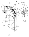
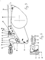
- the drawing shows the arrangement of the backrest lock on the back only by indicating a backrest 40 belt retractor housed in the backrest with the addition of the vehicle-fixed parts, so that the overall device with its function is sufficiently clear.
- FIGS. 1 and 2 shows the upright backrest position and thus also the upright position of a belt retractor 10 with a housing 11 with pronounced side walls.
- a winding shaft 12 on which the belt 13 is wound, which is led out of the belt retractor 10 via a belt deflection 14 which is fixed to the housing.
- a claw disk 16 is rotatably attached to a rivet 15, which is held in a pivoted-out position (FIG. 3) under the action of a spring 17 which is suspended on the housing side and tensions with the claw disk 16.
- the area of the belt retractor housing 11 holding the claw disk 16 is cranked to a smaller housing width (FIGS. 2 and 4).
- the claw plate 16 has a recess 18 which includes a bolt 20 arranged on a holder 19 fixed to the vehicle when the backrest is locked.
- the belt retractor housing 11 has a retraction 21 in the pivoting range of the claw disk 16 such that the bolt 20 is located in the deepest part of the retraction 21 when the backrest is locked. Since the center lines of the claw plate recess 18 and the housing recess 21 intersect, the bolt 20 of the housing-fixed holder 19 is firmly locked to the claw plate 16 and thus in turn to the housing 11 of the belt retractor 10 when the backrest is locked.
- the claw disk 16, which is under the action of the spring 17, is held in this position by a bolt 22 which is pivotably mounted in the belt retractor housing 11 and which can consist of a flat material and is spring-loaded.
- the bolt 22 engages a nose 23 of the claw disk 16; the bolt is movable in a recess 24 in the side legs of the belt retractor housing 11 between the locking position shown in FIG. 1 and a release position in which the bolt 22 releases the nose 23 of the claw disc 16 so that it then swings out under the action of the spring 17 can.
- a rocker arm 25 is pivotally mounted in the housing 11 about a pivot point 26, which acts on the bolt 22 accordingly.
- the rocker arm 25 (FIG. 2) can alternatively be actuated by a Bowden cable 27 or a plunger 28 which acts directly on the rocker arm 25, in the direction of the arrow 29.
- FIG 3 the position of the above components of the backrest lock is shown in the folded position of the backrest.
- the claw disk 16 is pivoted out so that it projects beyond the belt retractor housing 11 with a retaining lug 30.
- a retaining device is arranged on a part of the body which is fixed to the vehicle and which comprises a retaining disc 32 loaded with a spring 31; this holding disk 32 hooks when the backrest is folded down behind the retaining lug 30 of the claw disk 16, so that the belt retractor housing 11 and thus the backrest are locked to the body.
- To release the retaining washer 32 it is rotated via a Bowden cable 33 in the direction of arrow 34 and thus disengages from the retaining lug 30 of the claw disk 16, so that the backrest can be folded up past the retaining device 32.
- the device according to the invention works as follows: starting from the locked, folded up Position of the backrest is acted upon by actuating either the Bowden cable 27 or the plunger 28 on the rocker arm 25, whereby this turns the bolt 22 in the recess 24 of the belt retractor housing 11 so that the bolt 22 releases the nose 23 of the claw plate 16; this springs up under the action of the spring 17 and thus enables the bolt of the body-fixed holder 19 to slide out of the recess 21 of the housing 11 - the backrest can be folded down in the direction of the arrow 35.
- the claw disk 16 projects with a retaining lug 30 over the housing 11 and hooks in the folded position provided behind a spring-loaded retaining disk 32 arranged on the body. In this way, a secure locking with a straight flow of force is provided in both positions.
- the holding disk 32 is rotated so that it releases the retaining lug 30 of the claw disk 16 - the backrest can be folded up again in the direction of arrow 36.
- the pin 20 of the holder 19 fixed to the body engages in the recess 21 of the belt retractor housing 11 and thus comes into contact with the associated inner edge of the recess 18 in the claw disk 16 and thereby rotates the claw disk 16 until the pin 20 in Deepest of the confiscation 21 is located. Due to the assignment of the parts to each other given by the center lines of the recess 18 of the claw plate 16 and the recess 21 of the housing 11, the bolt is fixed in the deepest part of the recess 21 of the housing 11 by the claw plate 16, the Claw washer is held and locked in this end position by the spring-loaded bolt 22.
- the belt retractor housing 11 Due to the design of the belt retractor housing 11 in the form of two one-piece mirror-image housing parts, in which both the belt winding shaft 12 is mounted and the locking device 16, 22 is integrated, there is an optimal power transmission with a direct power flow from the belt winding shaft 12 to the locking part in the event of loading the latter is neither screwed on nor riveted nor is it otherwise provided with a connection which represents a weak point.
Landscapes
- Engineering & Computer Science (AREA)
- Mechanical Engineering (AREA)
- Aviation & Aerospace Engineering (AREA)
- Transportation (AREA)
- Seats For Vehicles (AREA)
- Automotive Seat Belt Assembly (AREA)
Applications Claiming Priority (2)
| Application Number | Priority Date | Filing Date | Title |
|---|---|---|---|
| DE3635071 | 1986-10-15 | ||
| DE19863635071 DE3635071A1 (de) | 1986-10-15 | 1986-10-15 | Rueckenlehnenverriegelung fuer einen mit sicherheitsgurten ausgeruesteten fahrzeugsitz |
Publications (3)
| Publication Number | Publication Date |
|---|---|
| EP0267450A2 true EP0267450A2 (fr) | 1988-05-18 |
| EP0267450A3 EP0267450A3 (en) | 1989-09-13 |
| EP0267450B1 EP0267450B1 (fr) | 1992-04-22 |
Family
ID=6311765
Family Applications (1)
| Application Number | Title | Priority Date | Filing Date |
|---|---|---|---|
| EP87114930A Expired - Lifetime EP0267450B1 (fr) | 1986-10-15 | 1987-10-13 | Dispositif de verrouillage d'un dossier de siège pour siège de véhicule pourvu d'une ceinture de sécurité |
Country Status (3)
| Country | Link |
|---|---|
| EP (1) | EP0267450B1 (fr) |
| DE (2) | DE3635071A1 (fr) |
| ZA (1) | ZA877705B (fr) |
Cited By (1)
| Publication number | Priority date | Publication date | Assignee | Title |
|---|---|---|---|---|
| EP0633169A1 (fr) * | 1993-07-08 | 1995-01-11 | Cesa Compagnie Europeenne De Sieges Pour Automobiles | Support articulé pour enrouleur de ceinture de sécurité et son application à un dossier rabattable de siège |
Families Citing this family (3)
| Publication number | Priority date | Publication date | Assignee | Title |
|---|---|---|---|---|
| DE3804550C2 (de) * | 1986-10-15 | 1993-12-02 | Autoflug Gmbh | Rückenlehnenverriegelung für einen mit Sicherheitsgurten ausgerüsteten Fahrzeugsitz |
| DE29803764U1 (de) * | 1998-03-04 | 1998-05-14 | Audi Ag, 85057 Ingolstadt | Umklappbare Rückenlehne eines Fahrzeugsitzes mit einer Lehnen-Verriegelungsvorrichtung und einer Sicherheitsgurt-Aufrollvorrichtung |
| DE10324979B4 (de) * | 2003-06-03 | 2005-06-02 | Keiper Gmbh & Co. Kg | Lehnenstruktur für eine klappbare Lehne eines Fahrzeugsitzes |
Family Cites Families (13)
| Publication number | Priority date | Publication date | Assignee | Title |
|---|---|---|---|---|
| GB1099649A (en) * | 1966-02-01 | 1968-01-17 | Ford Motor Co | Locks |
| US3880379A (en) * | 1971-12-21 | 1975-04-29 | Allied Chem | Retractor with switch |
| DE2747398A1 (de) * | 1976-10-22 | 1978-05-03 | Stig Martin Lindblad | Rueckhaltevorrichtung fuer fahrzeugsitze |
| FR2449550A1 (fr) * | 1979-02-22 | 1980-09-19 | Peugeot | Siege transformable de vehicule automobile equipe d'un dispositif d'accrochage pour ceintures de securite |
| DE2923550A1 (de) * | 1979-06-09 | 1981-01-22 | Volkswagenwerk Ag | Sitz fuer fahrzeuge, insbesondere personenkraftfahrzeuge |
| DE2924144A1 (de) * | 1979-06-15 | 1981-01-08 | Volkswagenwerk Ag | Sicherheitsgurtanordnung fuer insbesondere mit umklappbaren lehnen versehene fondsitze von personenkraftfahrzeugen |
| DE3021126A1 (de) * | 1980-06-04 | 1981-12-10 | Daimler-Benz Ag, 7000 Stuttgart | Fahrzeug, insbes. personenkraftfahrzeug, mit fahrzeugsitz und sicherheitsgurt |
| US4475769A (en) * | 1982-07-23 | 1984-10-09 | General Motors Corporation | Hinge and latch arrangement for vehicle seats |
| DE3319065A1 (de) * | 1983-05-26 | 1984-11-29 | Volkswagenwerk Ag, 3180 Wolfsburg | Sicherheitsgurt-befestigungsanordnung |
| HU193083B (en) * | 1984-02-22 | 1987-08-28 | Sandoz Ag | Process for preparing diazepinoindole derivatives further pharmaceutical compositions containing such compounds |
| DE3505047A1 (de) * | 1984-12-15 | 1986-06-26 | Kiekert GmbH & Co KG, 5628 Heiligenhaus | Rueckwaertiger kraftfahrzeugsitz mit sitzbank, zugleich als ladeflaeche einsetzbarer rueckenlehne und rueckenlehnen-gelenkbeschlag |
| DE3510006C1 (de) * | 1985-03-20 | 1986-06-12 | P.A. Rentrop, Hubbert & Wagner Fahrzeugausstattungen Gmbh & Co Kg, 3060 Stadthagen | Verriegelungseinrichtung für die Rückenlehne eines hinteren Kraftfahrzeugsitzes |
| DE3532407A1 (de) * | 1985-09-11 | 1987-03-12 | Autoflug Gmbh | Sitzintegriertes sicherheitsgurtsystem |
-
1986
- 1986-10-15 DE DE19863635071 patent/DE3635071A1/de active Granted
-
1987
- 1987-10-13 DE DE8787114930T patent/DE3778489D1/de not_active Expired - Fee Related
- 1987-10-13 EP EP87114930A patent/EP0267450B1/fr not_active Expired - Lifetime
- 1987-10-14 ZA ZA877705A patent/ZA877705B/xx unknown
Cited By (2)
| Publication number | Priority date | Publication date | Assignee | Title |
|---|---|---|---|---|
| EP0633169A1 (fr) * | 1993-07-08 | 1995-01-11 | Cesa Compagnie Europeenne De Sieges Pour Automobiles | Support articulé pour enrouleur de ceinture de sécurité et son application à un dossier rabattable de siège |
| FR2707229A1 (fr) * | 1993-07-08 | 1995-01-13 | Cesa | Support articulé pour enrouleur de ceinture de sécurité et son application à un dossier rabattable de siège. |
Also Published As
| Publication number | Publication date |
|---|---|
| DE3778489D1 (de) | 1992-05-27 |
| EP0267450A3 (en) | 1989-09-13 |
| EP0267450B1 (fr) | 1992-04-22 |
| DE3635071A1 (de) | 1988-04-28 |
| ZA877705B (en) | 1988-04-19 |
| DE3635071C2 (fr) | 1990-05-23 |
Similar Documents
| Publication | Publication Date | Title |
|---|---|---|
| DE19641089C2 (de) | Kopfstützen-Unterbringungsmechanismus für einen Fahrzeugsitz, insbesondere Kraftfahrzeugsitz | |
| DE3216015A1 (de) | Verankerung fuer das gurtschloss eines sicherheitsgurtes | |
| DE4012860A1 (de) | Fahrzeugsitz, insbesondere kraftfahrzeugsitz | |
| DE2252356C2 (de) | Sicherheitsgurtanordnung | |
| EP0537494A1 (fr) | Dispositif d'actionnement pour le frein à main des véhicules à moteur | |
| DE69628941T2 (de) | Anordnung für sicherheitsgurt | |
| DE2927159A1 (de) | Sicherheitsgurt-aufwickelvorrichtung | |
| EP0267450A2 (fr) | Dispositif de verrouillage d'un dossier de siège pour siège de véhicule pourvu d'une ceinture de sécurité | |
| EP0763444A2 (fr) | Siège arrière pour véhicules automobiles, en particulier pour voitures | |
| DE2414952A1 (de) | Gurtband-blockiereinrichtung | |
| DE3872825T2 (de) | Kugelsensor fuer sicherheitsgurtaufroller, insbesondere fuer kraftfahrzeuge. | |
| DE69002038T2 (de) | Lösbare Befestigungsvorrichtung für einen Rücksitz eines Kraftfahrzeuges. | |
| DE102011121244A1 (de) | Sicherungselement und Vorrichtung zur Sicherung von Ladegut in einem Fahrzeug | |
| DE2923550A1 (de) | Sitz fuer fahrzeuge, insbesondere personenkraftfahrzeuge | |
| DE1949085B2 (de) | Fahrzeugsitz, insbesondere Kraftfahrzeugsitz | |
| DE3826932A1 (de) | Kinder-sicherheitssitz | |
| EP0818371A1 (fr) | Agencement de fixation d'une ceinture de sécurité | |
| DE19750410C2 (de) | Gepäckrückhaltesystem | |
| DE102024001434B4 (de) | Vorrichtung zur Verriegelung einer Armlehne im Fondbereich eines Fahrzeuges | |
| DE102016120879B3 (de) | Laderaumtrennnetz mit Sicherheitsbefestigung | |
| DE8627511U1 (de) | Rückenlehnenverriegelung für einen mit Sicherheitsgurten ausgerüsteten Fahrzeugsitz | |
| DE19736033C2 (de) | Fahrzeugsitz mit klappbarer Rückenlehne | |
| DE2844858A1 (de) | Anordnung zur befestigung eines sicherheitsgurtes | |
| DE2817244A1 (de) | Befestigungseinrichtung fuer ein gurtschloss eines sicherheitsgurtes | |
| DE2510726A1 (de) | Fahrzeugsitz mit spannungslosem aufrollmechanismus |
Legal Events
| Date | Code | Title | Description |
|---|---|---|---|
| PUAI | Public reference made under article 153(3) epc to a published international application that has entered the european phase |
Free format text: ORIGINAL CODE: 0009012 |
|
| AK | Designated contracting states |
Kind code of ref document: A2 Designated state(s): DE FR GB IT SE |
|
| PUAL | Search report despatched |
Free format text: ORIGINAL CODE: 0009013 |
|
| AK | Designated contracting states |
Kind code of ref document: A3 Designated state(s): DE FR GB IT SE |
|
| 17P | Request for examination filed |
Effective date: 19900308 |
|
| 17Q | First examination report despatched |
Effective date: 19900905 |
|
| RAP1 | Party data changed (applicant data changed or rights of an application transferred) |
Owner name: AUTOFLUG GMBH & CO FAHRZEUGTECHNIK |
|
| GRAA | (expected) grant |
Free format text: ORIGINAL CODE: 0009210 |
|
| AK | Designated contracting states |
Kind code of ref document: B1 Designated state(s): DE FR GB IT SE |
|
| REF | Corresponds to: |
Ref document number: 3778489 Country of ref document: DE Date of ref document: 19920527 |
|
| ITF | It: translation for a ep patent filed | ||
| ET | Fr: translation filed | ||
| GBT | Gb: translation of ep patent filed (gb section 77(6)(a)/1977) | ||
| PG25 | Lapsed in a contracting state [announced via postgrant information from national office to epo] |
Ref country code: SE Effective date: 19921014 |
|
| PLBE | No opposition filed within time limit |
Free format text: ORIGINAL CODE: 0009261 |
|
| STAA | Information on the status of an ep patent application or granted ep patent |
Free format text: STATUS: NO OPPOSITION FILED WITHIN TIME LIMIT |
|
| 26N | No opposition filed | ||
| EUG | Se: european patent has lapsed |
Ref document number: 87114930.8 Effective date: 19930510 |
|
| REG | Reference to a national code |
Ref country code: GB Ref legal event code: IF02 |
|
| PGFP | Annual fee paid to national office [announced via postgrant information from national office to epo] |
Ref country code: DE Payment date: 20051006 Year of fee payment: 19 |
|
| PGFP | Annual fee paid to national office [announced via postgrant information from national office to epo] |
Ref country code: FR Payment date: 20051010 Year of fee payment: 19 |
|
| PGFP | Annual fee paid to national office [announced via postgrant information from national office to epo] |
Ref country code: GB Payment date: 20051012 Year of fee payment: 19 |
|
| PG25 | Lapsed in a contracting state [announced via postgrant information from national office to epo] |
Ref country code: IT Free format text: LAPSE BECAUSE OF NON-PAYMENT OF DUE FEES;WARNING: LAPSES OF ITALIAN PATENTS WITH EFFECTIVE DATE BEFORE 2007 MAY HAVE OCCURRED AT ANY TIME BEFORE 2007. THE CORRECT EFFECTIVE DATE MAY BE DIFFERENT FROM THE ONE RECORDED. Effective date: 20051013 |
|
| PG25 | Lapsed in a contracting state [announced via postgrant information from national office to epo] |
Ref country code: DE Free format text: LAPSE BECAUSE OF NON-PAYMENT OF DUE FEES Effective date: 20070501 |
|
| GBPC | Gb: european patent ceased through non-payment of renewal fee |
Effective date: 20061013 |
|
| REG | Reference to a national code |
Ref country code: FR Ref legal event code: ST Effective date: 20070629 |
|
| PG25 | Lapsed in a contracting state [announced via postgrant information from national office to epo] |
Ref country code: GB Free format text: LAPSE BECAUSE OF NON-PAYMENT OF DUE FEES Effective date: 20061013 |
|
| PG25 | Lapsed in a contracting state [announced via postgrant information from national office to epo] |
Ref country code: FR Free format text: LAPSE BECAUSE OF NON-PAYMENT OF DUE FEES Effective date: 20061031 |