EP0267528A2 - Système numérique de transmission de données comprenant des répéteurs adressables et des dispositifs de localisation d'erreurs - Google Patents
Système numérique de transmission de données comprenant des répéteurs adressables et des dispositifs de localisation d'erreurs Download PDFInfo
- Publication number
- EP0267528A2 EP0267528A2 EP19870116189 EP87116189A EP0267528A2 EP 0267528 A2 EP0267528 A2 EP 0267528A2 EP 19870116189 EP19870116189 EP 19870116189 EP 87116189 A EP87116189 A EP 87116189A EP 0267528 A2 EP0267528 A2 EP 0267528A2
- Authority
- EP
- European Patent Office
- Prior art keywords
- address
- locating device
- regenerator
- regenerators
- memory
- Prior art date
- Legal status (The legal status is an assumption and is not a legal conclusion. Google has not performed a legal analysis and makes no representation as to the accuracy of the status listed.)
- Granted
Links
- 230000005540 biological transmission Effects 0.000 title claims abstract description 34
- 230000004807 localization Effects 0.000 title 1
- 230000015572 biosynthetic process Effects 0.000 claims description 9
- 230000002457 bidirectional effect Effects 0.000 claims description 5
- 238000001514 detection method Methods 0.000 claims description 5
- 238000000034 method Methods 0.000 claims description 3
- 230000008569 process Effects 0.000 claims description 3
- 238000004519 manufacturing process Methods 0.000 abstract 2
- 238000005259 measurement Methods 0.000 description 9
- 238000012360 testing method Methods 0.000 description 4
- 230000008901 benefit Effects 0.000 description 3
- 238000010586 diagram Methods 0.000 description 3
- 241001136792 Alle Species 0.000 description 2
- 238000011161 development Methods 0.000 description 2
- 230000018109 developmental process Effects 0.000 description 2
- 230000006870 function Effects 0.000 description 2
- 238000002955 isolation Methods 0.000 description 2
- 230000001960 triggered effect Effects 0.000 description 2
- 230000009977 dual effect Effects 0.000 description 1
- 230000000694 effects Effects 0.000 description 1
- 238000011156 evaluation Methods 0.000 description 1
- 230000009467 reduction Effects 0.000 description 1
- 230000004044 response Effects 0.000 description 1
Images
Classifications
-
- H—ELECTRICITY
- H04—ELECTRIC COMMUNICATION TECHNIQUE
- H04B—TRANSMISSION
- H04B17/00—Monitoring; Testing
- H04B17/40—Monitoring; Testing of relay systems
- H04B17/401—Monitoring; Testing of relay systems with selective localization
- H04B17/406—Monitoring; Testing of relay systems with selective localization using coded addresses
Definitions
- the invention relates to intermediate regenerators provided with addresses for a digital message transmission system and to a location device for a bidirectional digital message transmission system with such intermediate regenerators and finally to a digital message transmission system with intermediate regenerators and a locating device.
- a problem with the systems of the first type is that the address of an intermediate regenerator must be set individually, so that the systems of the second type are often preferred because of this problem.
- an intermediate regenerator is known for a system of the first type, which has an address memory for a digital address. It is said there that this address is the address assigned to the intermediate regenerator, but nothing is said about what criterion or how the address was assigned to the intermediate regenerator, how the addresses assigned to the intermediate regenerators are entered into the locating device, and the way in which the locating device obtains knowledge of the location within the system of the intermediate regenerator with a specific address.
- the object is achieved with respect to the intermediate regenerator as specified in claim 1 and with respect to the locating device as specified in claim 3.
- a message transmission system with an intermediate regenerator according to the invention and a locating device according to the invention is the subject of claim 7. Further developments of the intermediate regenerator result from claims 2 and 5 and further developments of the locating device from claim 4.
- the intermediate regenerator according to the invention and the system equipped therewith has the advantage that when an intermediate regenerator is installed in the system, it does not Ne address setting is required, not even when installing an additional intermediate regenerator or replacing an existing intermediate regenerator with a new one.
- the intermediate regenerator receives its address when it is manufactured, which, wherever it is used, is attached to it like a serial number.
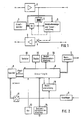
- the 1 consists of two identically constructed regenerators 1 and 2 for two transmission directions and a common device for fault location.
- this has an address memory 3 for the address assigned to the intermediate regenerator.
- the address is stored unchangeably in this address memory and therefore belongs inseparably to this device, just as a serial number cannot be changed and is inseparable from a device.
- the address is, for example, a specific number for this device in a dual representation, which is chosen such that two different intermediate regenerators have never stored the same number as the address in their address memory 3.
- the address memory 3 is a digital read-only memory, the programming of which cannot be changed.
- a loop formation is also possible in the new intermediate regenerator according to FIG. 1 in that the output of the regenerator 1 for one transmission direction is connected to the input of the regenerator 2 for the other transmission direction via a controllable switch S.
- a galvanic isolation 4 is inserted, which is indicated by a transformer.
- the end point of the system is the end point that sends in the direction of the regenerator 1, that is to say in the illustration according to FIG. 1 "on the left side" of the system.
- a command detection and control circuit 5 is connected via the circuit 4 provided for electrical isolation to the output of the regenerator 1 and also to the output of the address memory 3.
- the command detection and control circuit 5 is capable of comparing the location or remote control Compare the address sent out and received by all intermediate regenerators with the individual address stored in the address memory 3 and also to recognize the commands sent from the end point and to initiate the execution of the commands. Instructions are to be understood as those which are in connection with the address of a special intermediate rain rators are sent out and are therefore directed only to this special intermediate regenerator and those commands which are sent out unrelated to any address and are directed to all intermediate regenerators of the system. In the intermediate regenerator shown in Fig.
- the command detection and control circuit 5 controls the switch S upon receipt of a corresponding command so that it assumes the switch position, not shown, and thus the loop closes and, in turn, controls a transmitter SE with a corresponding command, which can be connected on the input side to the address memory 3 and on the output side via the switch S to the input of the regenerator 2, so that it sends out the address of the intermediate regenerator. Examples of this for cooperation with a locating device of the system according to the invention to be explained are also given.
- FIG. 2 is provided for a bidirectional message transmission system with the intermediate regenerators according to the invention according to FIG Carrying out the fault location offers.
- a word generator 7 controlled by the control logic 6 is used to generate and send out these commands.
- the locating device according to FIG. 2 works as described below with the intermediate regenerator according to FIG. 1.
- the locating device When the locating device is connected to the terminal for fault location, it initially has no information about which addresses the intermediate regenerators of the system have and which address-provided intermediate regenerators are located at which location within the message transmission path. The locating device therefore initially has no possibility of specifically controlling the intermediate regenerators.
- the devices according to the invention to be described with reference to FIG. 2 are present in the locating device, which enable the locating device to query the intermediate regenerators one after the other according to their local order in the system for their addresses and these in a memory together with the location the intermediate regenerators to save.
- this can be carried out either only once after starting up the locating device or from time to time, triggered by manual operation or by a clock or by remote control from a computer.
- the control logic 6 is connected to a memory 8, in which the address of an intermediate regenerator and, on the other hand, its position within the system are stored. These two pieces of information are assigned to one another in the memory, so that the information for an intermediate regenerator in the memory 8 is that it has an address XYZ and, viewed from the locating terminal, is, for example, the fifth of the intermediate regenerators of the system located one behind the other. If any of the intermediate regenerators on the route sends its address to the locating device after a query which is yet to be explained, then this arrives at a receiver 9, the output of which is connected to a measuring device 10 and to a series-parallel converter 11.
- the measuring device When the control logic 6 gives the intermediate regenerators the command to send out their address, the measuring device receives a trigger signal from the control logic and is thus in a position when the receiver 9 receives an address between the sending of the query command and the arrival of the latter Address elapsed time to measure. The measuring device gives this measurement result to the control logic 6, which then recognizes on the basis of the transit times that it was an intermediate regenerator with a specific location from which the address was just received. (The system's intermediate regenerators follow one another at approximately regular intervals). After this evaluation of the received address, the parallel-series converter 11 enters the address in the memory 8 and at the same time the control logic enters the location of the associated intermediate regenerator in this memory. The address is stored in the memory 8 together with the associated location.
- the intermediate regenerators are queried for their addresses as follows: initiated by an operator via a keyboard 12 connected to the control logic 6 or automatically, depending on the status of a clock 13 connected to the control logic 6, or by a computer connected to the control logic 6 connected computer interface circuit 14 remotely controlled, the control logic 6 begins the polling process. For this purpose, it causes the word generator 7 to send out the word W1 via the system in order to request all intermediate regenerators to send their address back to the locating device.
- Each intermediate regenerator recognizes this word in its command recognition and control circuit 5 (FIG. 1), which then switches the switch S in each intermediate regenerator and closes the loop and immediately afterwards causes the transmitter SE to address the address stored in the address memory 3 via the regenerator 2 to be sent on the transmission path towards the locating device.
- the runtime is measured for the address, the location of the intermediate regenerator sending the address is determined as a function thereof, and the received address is stored in the memory 8 together with the associated location of the intermediate regenerator.
- the control logic 6 then causes the word generator 7 to send the word W3 to the intermediate regenerators in connection with the address just received and stored.
- the command recognition and control circuit 5 of the first intermediate regenerator now recognizes the own address sent by the locating device and the word W3 and then assumes the waiting state. This means that it brings the switch S back into the position shown in FIG. 1, so that the loop formation in the first intermediate regenerator breaks up and connects this intermediate regenerator to the second intermediate regenerator behind it and maintains this connection even if it again uses the word W1 (command for sending addresses).
- an intermediate regenerator thus ignores the reception of the word W1, the word W2 and the word W3 and remains unchanged in this state. Only the word W4, which gives the command for all intermediate regenerators to assume the operating state, ends the waiting state of an intermediate regenerator.
- the word generator of the locating device sends the word W1 over the transmission link to all intermediate regenerators.
- the first intermediate regenerator in the waiting state ignores this command and maintains the switch position shown in FIG. 1, in which it is connected to the one behind it. Those behind react to the word W1 as described above by closing the loop and sending their address via their regenerator 2 in the direction of the locating device.
- the second intermediate regenerator is connected to the locating device via the first intermediate regenerator, while the intermediate regenerators behind them are cut off from the transmission path to the locating device because of the loop closure present in each case, ie they send their address "into space".
- the address of the second intermediate regenerator is now received in the locating device and, as described for the address of the first intermediate regenerator above, is stored in the memory 8 together with the associated location. Thereupon, the word generator 7 of the locating device sends the word W3 provided with the address of the second intermediate regenerator via the transmission link, which causes this second intermediate regenerator to assume the waiting state.
- the command detection and control circuit 5 effects a so-called "forced reset" in the operating state, regardless of the receipt of the word W4, if it is within a predetermined time, e.g. Has not received any of the words W1 to W3 for 10 seconds.
- the forced reset ensures that a faulty loop closure in any repeater is reversed after a short time and the transmission can only be briefly disturbed in the operating state.
- Words W1 to W4 are to be understood as n-bit words which contain the actual command with sufficient redundancy and security.
- the locating device After knowing the addresses of the existing intermediate regenerators and the associated location, the locating device is able to carry out measurements at any time in order to examine the quality of the transmission path from the locating terminal to one of the intermediate regenerators by remotely closing the loop in any intermediate regenerator.
- the locating device contains a display 15 connected to the control logic 6 and a printer interface circuit 16, which is also connected to the control logic 6 and allows measurement logs to be printed out on a printer.
- the word generator sends out the word W2 in connection with the address of this intermediate regenerator, which causes the loop to close.
- the word W is repeatedly shown in the transmitted test pattern in order to avoid that the forced reset is activated.
- the word W4 is sent, which brings all intermediate regenerators back into the operating state.
- the locating device for measuring the transmission link to the first intermediate regenerator sends the word W2 to this first intermediate regenerator, after measurement the word W3 to this intermediate regenerator and after measuring the transmission link to it second intermediate regenerator, the word W3 to this intermediate regenerator, etc. until the transmission path to all intermediate regenerators has been measured one after the other, whereupon the word W4, which concludes the entire measurement, is finally sent out, which brings all intermediate regenerators back into the operating state, if they have not already been through Forced reset went into this state by themselves.
Landscapes
- Physics & Mathematics (AREA)
- Electromagnetism (AREA)
- Engineering & Computer Science (AREA)
- Computer Networks & Wireless Communication (AREA)
- Signal Processing (AREA)
- Dc Digital Transmission (AREA)
- Small-Scale Networks (AREA)
- Time-Division Multiplex Systems (AREA)
Applications Claiming Priority (2)
| Application Number | Priority Date | Filing Date | Title |
|---|---|---|---|
| DE19863638147 DE3638147A1 (de) | 1986-11-08 | 1986-11-08 | Digitales nachrichtenuebertragungssystem mit adressen aufweisenden zwischenregeneratoren und einrichtung zur fehlerortung |
| DE3638147 | 1986-11-08 |
Publications (3)
| Publication Number | Publication Date |
|---|---|
| EP0267528A2 true EP0267528A2 (fr) | 1988-05-18 |
| EP0267528A3 EP0267528A3 (en) | 1989-11-02 |
| EP0267528B1 EP0267528B1 (fr) | 1993-08-11 |
Family
ID=6313502
Family Applications (1)
| Application Number | Title | Priority Date | Filing Date |
|---|---|---|---|
| EP87116189A Expired - Lifetime EP0267528B1 (fr) | 1986-11-08 | 1987-11-04 | Système numérique de transmission de données comprenant des répéteurs adressables et des dispositifs de localisation d'erreurs |
Country Status (6)
| Country | Link |
|---|---|
| US (1) | US4939747A (fr) |
| EP (1) | EP0267528B1 (fr) |
| JP (1) | JPS63219250A (fr) |
| AU (1) | AU595951B2 (fr) |
| DE (2) | DE3638147A1 (fr) |
| ES (1) | ES2044891T3 (fr) |
Cited By (2)
| Publication number | Priority date | Publication date | Assignee | Title |
|---|---|---|---|---|
| EP0433527A1 (fr) * | 1989-12-21 | 1991-06-26 | Zumtobel Aktiengesellschaft | Dispositif de commande pour plusieurs utilisateurs |
| WO1991010276A1 (fr) * | 1989-12-21 | 1991-07-11 | Zumtobel Aktiengesellschaft | Dispositif de commande pour plusieurs consommateurs |
Families Citing this family (14)
| Publication number | Priority date | Publication date | Assignee | Title |
|---|---|---|---|---|
| GB8927623D0 (en) * | 1989-12-06 | 1990-02-07 | Bicc Plc | Repeaters for secure local area networks |
| CH682030A5 (fr) * | 1991-01-15 | 1993-06-30 | Peter Vockenhuber | |
| US5422929A (en) * | 1991-11-13 | 1995-06-06 | Txport, Inc. | Telephone line repeater and method of testing same |
| US5600656A (en) * | 1993-06-10 | 1997-02-04 | Siemens Stromberg-Carlson | Remote loopback apparatus and method for telephone line repeaters |
| US5717714A (en) * | 1995-01-30 | 1998-02-10 | Level One Communications, Inc. | Inter-repeater backplane with mixed signal state machine interconnect |
| US5680113A (en) * | 1995-02-24 | 1997-10-21 | International Business Machines Corporation | Dynamic address assignments to serially connected devices |
| US5726993A (en) * | 1995-10-25 | 1998-03-10 | Siemens Telecom Networks | Signal detector for telephone line repeator remote loopback system |
| US5887050A (en) * | 1997-05-09 | 1999-03-23 | Siemens Building Technologies, Inc. | Repeater apparatus having isolation circuit |
| DE19942690A1 (de) * | 1999-09-07 | 2001-03-15 | Siemens Ag | Lokalisierung eines gestörten Streckenabschnitts in einer aktiven Langzeitverbindung |
| US6829292B1 (en) * | 2000-01-03 | 2004-12-07 | Symmetricom, Inc. | Increasing gain with isolating upstream and downstream filters and amplifiers |
| GB2363498B (en) * | 2000-06-16 | 2005-06-01 | Marconi Caswell Ltd | Transponder device for generating a data bearing output |
| US6795871B2 (en) | 2000-12-22 | 2004-09-21 | General Electric Company | Appliance sensor and man machine interface bus |
| US7558192B1 (en) * | 2004-05-03 | 2009-07-07 | Cisco Technology, Inc. | Method to increase system availability of critical hardware components |
| DE102008035785A1 (de) | 2007-08-08 | 2009-02-12 | Tridonicatco Gmbh & Co. Kg | Adressierung von nach einem Montageplan installierten Aktoren und Steuersystem |
Family Cites Families (18)
| Publication number | Priority date | Publication date | Assignee | Title |
|---|---|---|---|---|
| US3950622A (en) * | 1974-10-15 | 1976-04-13 | Culbertson Industries Inc. | Line fault locating system |
| US4072923A (en) * | 1976-03-08 | 1978-02-07 | Western Geophysical Co. Of America | Multichannel seismic telemeter system and array former |
| IT1040148B (it) * | 1975-07-28 | 1979-12-20 | Sits Soc It Telecom Siemens | Sistema di telesorveglianza per sistemi di trasmissione pcm |
| US4301538A (en) * | 1978-11-02 | 1981-11-17 | Compagnie Industrielle Des Telecommunications Cit-Alcatel | Remote surveillance and fault location unit for pulse regenerator repeaters |
| FR2444983A1 (fr) * | 1978-12-22 | 1980-07-18 | Fillot Jean Jacques | Systeme de surveillance et de regulation d'une liaison de transmission |
| FR2454728A1 (fr) * | 1979-04-19 | 1980-11-14 | Telecommunications Sa | Procede et dispositif de telesurveillance de liaisons numeriques ou analogique de telecommunications |
| DE2942410A1 (de) * | 1979-10-19 | 1981-05-07 | Siemens AG, 1000 Berlin und 8000 München | Adressenfreie fehlerortung mittels schleifenschluss in einer nachrichtenuebertragungsstrecke |
| FR2486335B1 (fr) * | 1980-07-02 | 1988-03-11 | Telecommunications Sa | Installation de telelocalisation pas-a-pas de circuits d'amplification intermediaires d'une liaison mic |
| AU552312B2 (en) * | 1982-02-08 | 1986-05-29 | Racal-Milgo Limited | Communication system |
| JPS59132265A (ja) * | 1983-01-19 | 1984-07-30 | Nec Corp | Pcm搬送システムにおける中継器の監視方法 |
| JPS59172861A (ja) * | 1983-03-22 | 1984-09-29 | Toshiba Corp | ル−プバツク制御方式 |
| US4558464A (en) * | 1983-06-10 | 1985-12-10 | General Instrument Corporation | Address-programmable CATV converter |
| NL8303944A (nl) * | 1983-11-17 | 1985-06-17 | Philips Nv | Werkwijze voor het besturen van een bewakingsinrichting in een digitaal transmissiesysteem. |
| DE3401685A1 (de) * | 1984-01-19 | 1985-07-25 | Philips Patentverwaltung Gmbh, 2000 Hamburg | Verfahren zur fehlerortung |
| US4713808A (en) * | 1985-11-27 | 1987-12-15 | A T & E Corporation | Watch pager system and communication protocol |
| US4638298A (en) * | 1985-07-16 | 1987-01-20 | Telautograph Corporation | Communication system having message repeating terminals |
| US4653070A (en) * | 1985-09-11 | 1987-03-24 | Nec Corporation | Channel monitoring circuit for use in a repeater station over radio digital transmission |
| US4831558A (en) * | 1986-08-26 | 1989-05-16 | The Slope Indicator Company | Digitally based system for monitoring physical phenomena |
-
1986
- 1986-11-08 DE DE19863638147 patent/DE3638147A1/de not_active Withdrawn
-
1987
- 1987-11-04 DE DE8787116189T patent/DE3786983D1/de not_active Expired - Fee Related
- 1987-11-04 EP EP87116189A patent/EP0267528B1/fr not_active Expired - Lifetime
- 1987-11-04 ES ES87116189T patent/ES2044891T3/es not_active Expired - Lifetime
- 1987-11-05 US US07/117,595 patent/US4939747A/en not_active Expired - Fee Related
- 1987-11-05 AU AU80824/87A patent/AU595951B2/en not_active Ceased
- 1987-11-06 JP JP62279435A patent/JPS63219250A/ja active Pending
Cited By (3)
| Publication number | Priority date | Publication date | Assignee | Title |
|---|---|---|---|---|
| EP0433527A1 (fr) * | 1989-12-21 | 1991-06-26 | Zumtobel Aktiengesellschaft | Dispositif de commande pour plusieurs utilisateurs |
| WO1991010276A1 (fr) * | 1989-12-21 | 1991-07-11 | Zumtobel Aktiengesellschaft | Dispositif de commande pour plusieurs consommateurs |
| US5352957A (en) * | 1989-12-21 | 1994-10-04 | Zumtobel Aktiengessellschaft | Appliance control system with programmable receivers |
Also Published As
| Publication number | Publication date |
|---|---|
| DE3786983D1 (de) | 1993-09-16 |
| EP0267528A3 (en) | 1989-11-02 |
| DE3638147A1 (de) | 1988-05-11 |
| JPS63219250A (ja) | 1988-09-12 |
| AU595951B2 (en) | 1990-04-12 |
| AU8082487A (en) | 1988-05-26 |
| ES2044891T3 (es) | 1994-01-16 |
| US4939747A (en) | 1990-07-03 |
| EP0267528B1 (fr) | 1993-08-11 |
Similar Documents
| Publication | Publication Date | Title |
|---|---|---|
| DE1809913C3 (de) | Verfahren und Datenübermittlungsanlage zur Übertragung von Daten zwischen einer Haupteinheit und mehreren Endstelleneinheiten | |
| DE3342430C2 (fr) | ||
| EP0267528B1 (fr) | Système numérique de transmission de données comprenant des répéteurs adressables et des dispositifs de localisation d'erreurs | |
| DE3136128C2 (fr) | ||
| DE2362344A1 (de) | Datenuebertragungsanlage | |
| DE3431171A1 (de) | Gleisfreimeldeeinrichtung mit achszaehlung | |
| DE2817089B2 (de) | Gefahrenmeldeanlage | |
| DE68927400T2 (de) | Systemeinrichtung zur Sammlung von Alarmsignalen einer Stationskette | |
| DE2628905A1 (de) | Zugsicherungs- und -steuerungsanlage | |
| DE2354067B2 (de) | Verfahren und einrichtung zum fernsteuern von objekten | |
| EP0256152B1 (fr) | Méthode de génération d'un signal de connexion dans un récepteur de radiodiffusion ou de vidéo | |
| DE2339392C3 (de) | Verfahren zum Aufrufen von Außenstationen durch eine Zentralstation und SHALTUNGSANORDNUNG ZUR Durchführung dieses Verfahrens | |
| DE2456630C3 (de) | Fernsteueranlage | |
| DE2264085C2 (de) | Fernwirkanlage mit wenigstens einer Hauptzentrale, der ein Hauptnetz zugeordnet ist | |
| DE3327489C2 (fr) | ||
| DE19843449A1 (de) | Netzwerk sowie Koppelgerät zur Verbindung zweier Segmente in einem derartigen Netzwerk | |
| DE3029803C2 (de) | Kabelfernsehsystem | |
| DE3634019A1 (de) | Vorrichtung und verfahren zum seriellen datenaustausch zwischen mehr als zwei teilnehmern | |
| EP0036960A1 (fr) | Méthode et circuits pour la réception et la transmission de blocs de données, en particulier pour des systèmes de chemin de fer | |
| DE3047259C2 (de) | Schaltungsanordnung zur bidirektionalen Übermittlung von Informationen | |
| DE2346749C2 (de) | Schaltungsanordnung zum gesicherten Aussenden und Empfangen von Befehlen in Fernwirkanlagen | |
| DE3726573C2 (fr) | ||
| EP0214475A1 (fr) | Circuit pour transmettre des signaux de données entre des dispositifs de commande reliées entre eux par un système en anneaux | |
| EP0392246B1 (fr) | Système de surveillance et de commande pour systèmes de transmission d'informations numériques avec maître et maître de substitution | |
| EP0348810A2 (fr) | Méthode pour l'adressage d'unités de processeur et circuit pour la mise en oeuvre de la méthode |
Legal Events
| Date | Code | Title | Description |
|---|---|---|---|
| PUAI | Public reference made under article 153(3) epc to a published international application that has entered the european phase |
Free format text: ORIGINAL CODE: 0009012 |
|
| AK | Designated contracting states |
Kind code of ref document: A2 Designated state(s): AT BE CH DE ES FR GB IT LI NL SE |
|
| PUAL | Search report despatched |
Free format text: ORIGINAL CODE: 0009013 |
|
| AK | Designated contracting states |
Kind code of ref document: A3 Designated state(s): AT BE CH DE ES FR GB IT LI NL SE |
|
| 17P | Request for examination filed |
Effective date: 19891123 |
|
| 17Q | First examination report despatched |
Effective date: 19920130 |
|
| RAP3 | Party data changed (applicant data changed or rights of an application transferred) |
Owner name: ALCATEL SEL AKTIENGESELLSCHAFT |
|
| RBV | Designated contracting states (corrected) |
Designated state(s): DE ES FR GB IT |
|
| GRAA | (expected) grant |
Free format text: ORIGINAL CODE: 0009210 |
|
| AK | Designated contracting states |
Kind code of ref document: B1 Designated state(s): DE ES FR GB IT |
|
| GBT | Gb: translation of ep patent filed (gb section 77(6)(a)/1977) |
Effective date: 19930812 |
|
| REF | Corresponds to: |
Ref document number: 3786983 Country of ref document: DE Date of ref document: 19930916 |
|
| ITF | It: translation for a ep patent filed | ||
| ET | Fr: translation filed | ||
| REG | Reference to a national code |
Ref country code: ES Ref legal event code: FG2A Ref document number: 2044891 Country of ref document: ES Kind code of ref document: T3 |
|
| PLBE | No opposition filed within time limit |
Free format text: ORIGINAL CODE: 0009261 |
|
| STAA | Information on the status of an ep patent application or granted ep patent |
Free format text: STATUS: NO OPPOSITION FILED WITHIN TIME LIMIT |
|
| 26N | No opposition filed | ||
| PGFP | Annual fee paid to national office [announced via postgrant information from national office to epo] |
Ref country code: GB Payment date: 19971013 Year of fee payment: 11 |
|
| PGFP | Annual fee paid to national office [announced via postgrant information from national office to epo] |
Ref country code: FR Payment date: 19971113 Year of fee payment: 11 |
|
| PGFP | Annual fee paid to national office [announced via postgrant information from national office to epo] |
Ref country code: DE Payment date: 19971115 Year of fee payment: 11 |
|
| PGFP | Annual fee paid to national office [announced via postgrant information from national office to epo] |
Ref country code: ES Payment date: 19971117 Year of fee payment: 11 |
|
| PG25 | Lapsed in a contracting state [announced via postgrant information from national office to epo] |
Ref country code: GB Free format text: LAPSE BECAUSE OF NON-PAYMENT OF DUE FEES Effective date: 19981104 |
|
| PG25 | Lapsed in a contracting state [announced via postgrant information from national office to epo] |
Ref country code: ES Free format text: LAPSE BECAUSE OF THE APPLICANT RENOUNCES Effective date: 19981105 |
|
| GBPC | Gb: european patent ceased through non-payment of renewal fee |
Effective date: 19981104 |
|
| PG25 | Lapsed in a contracting state [announced via postgrant information from national office to epo] |
Ref country code: FR Free format text: LAPSE BECAUSE OF NON-PAYMENT OF DUE FEES Effective date: 19990730 |
|
| REG | Reference to a national code |
Ref country code: FR Ref legal event code: ST |
|
| PG25 | Lapsed in a contracting state [announced via postgrant information from national office to epo] |
Ref country code: DE Free format text: LAPSE BECAUSE OF NON-PAYMENT OF DUE FEES Effective date: 19990901 |
|
| REG | Reference to a national code |
Ref country code: ES Ref legal event code: FD2A Effective date: 20010402 |
|
| PG25 | Lapsed in a contracting state [announced via postgrant information from national office to epo] |
Ref country code: IT Free format text: LAPSE BECAUSE OF NON-PAYMENT OF DUE FEES;WARNING: LAPSES OF ITALIAN PATENTS WITH EFFECTIVE DATE BEFORE 2007 MAY HAVE OCCURRED AT ANY TIME BEFORE 2007. THE CORRECT EFFECTIVE DATE MAY BE DIFFERENT FROM THE ONE RECORDED. Effective date: 20051104 |