EP0267536A2 - Conduit fermé hermétiquement pour fibre en verre - Google Patents
Conduit fermé hermétiquement pour fibre en verre Download PDFInfo
- Publication number
- EP0267536A2 EP0267536A2 EP87116260A EP87116260A EP0267536A2 EP 0267536 A2 EP0267536 A2 EP 0267536A2 EP 87116260 A EP87116260 A EP 87116260A EP 87116260 A EP87116260 A EP 87116260A EP 0267536 A2 EP0267536 A2 EP 0267536A2
- Authority
- EP
- European Patent Office
- Prior art keywords
- solder
- hermetically sealed
- metal part
- glass fiber
- bushing according
- Prior art date
- Legal status (The legal status is an assumption and is not a legal conclusion. Google has not performed a legal analysis and makes no representation as to the accuracy of the status listed.)
- Granted
Links
Images



Classifications
-
- G—PHYSICS
- G02—OPTICS
- G02B—OPTICAL ELEMENTS, SYSTEMS OR APPARATUS
- G02B6/00—Light guides; Structural details of arrangements comprising light guides and other optical elements, e.g. couplings
- G02B6/44—Mechanical structures for providing tensile strength and external protection for fibres, e.g. optical transmission cables
- G02B6/4401—Optical cables
- G02B6/4415—Cables for special applications
- G02B6/4427—Pressure resistant cables, e.g. undersea cables
- G02B6/4428—Penetrator systems in pressure-resistant devices
-
- G—PHYSICS
- G02—OPTICS
- G02B—OPTICAL ELEMENTS, SYSTEMS OR APPARATUS
- G02B6/00—Light guides; Structural details of arrangements comprising light guides and other optical elements, e.g. couplings
- G02B6/24—Coupling light guides
- G02B6/42—Coupling light guides with opto-electronic elements
- G02B6/4201—Packages, e.g. shape, construction, internal or external details
- G02B6/4248—Feed-through connections for the hermetical passage of fibres through a package wall
Definitions
- the invention relates to a glass fiber implementation of the execution.
- Feedthroughs of this type are used, for example, in optical communications technology, in particular for hermetically sealed housings for electro-optical or optoelectric components which have to be protected against environmental influences.
- Metallot which has a higher temperature resistance than adhesive, is preferably used to fix the bare glass fiber. It also prevents the glass fiber from creeping, which sometimes occurs when the adhesive is fixed, and it is moisture-proof.
- the invention is therefore based on the object of providing a hermetically sealed glass fiber bushing according to the preamble of claim 1, which can be manufactured with less effort, has a high level of tightness and can, if necessary, be produced in the field.
- This object is achieved according to the invention by the constructive measures specified in the characterizing part of this claim.
- Further solutions to the problem on which the invention is based are specified in claims 10 and 15. Appropriate configurations of the subject matter according to claims 1, 10 and 15 can be found in the subclaims.
- Metallizing is no longer necessary with glass fibers.
- the previously required complex cleaning processes are no longer necessary.
- the bushing has a high and reliable degree of tightness, which is achieved even in the production of bushings in the field. Further advantages are given in the description below.
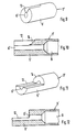
- a first metal part of the hermetically sealed glass fiber bushing is designated by 1.
- the first metal part 1 shown in FIGS. 1, 2 and 4 is preferably the wall of a hermetically sealed housing or a holding plate which can be arranged, for example, within such a housing.
- the metal part 1 passes through a bore 2, in which the glass fiber 3 is fastened by means of soldering.
- the glass fiber 3 is a bare, non-metallized end of an optical waveguide that has been freed from the primary coating.
- the bore 2 is either completely or at least partially filled with solder 4 and outside the bore 2 on at least one outside 5 of the metal part 1, a solder body 6 e.g. formed in the form of a solder bump.
- the solder 4 When the solder 4 cools, it shrinks outside of the bore 2 onto the bare glass fiber 3 and hermetically encloses it. Within the bore 2, however, it detaches from the glass fiber 3 when shrinking and forms a hermetically tight connection with the wetted bore wall. In this way, the transition between the inside of the bore 2 and the solder 4 located outside this forms a hermetic seal between the metal part 1 and glass fiber 3.
- the different coefficients of expansion of the two Materials also result in a firm, torsion-free fit of the glass fiber 3 in the solder 4. In the event of an impermissible tensile stress, it does not break inside or at the soldering point, but rather away from it.
- this second metal part 7 is a tab stamped from sheet metal (FIG. 3) with a retaining tab, the free end 8 of which is fastened to the outside 5 of the first metal part 1.
- a simple wire bracket can also form the height limit of the solder body 6.
- the second metal parts 7 are held at the desired distance from the first metal part during soldering with a simple tool. After the solder 4 has solidified, the glass fiber 3 is both hermetically sealed and the second metal part 7 is mechanically fastened to the first metal part 1 by the solder body 6.
- the second metal parts 7 connected to the solder body 6 can be designed as a fiber end sleeve, ring, perforated disk, holding plate or wall of a second housing.
- the first metal parts 1 likewise consist of sleeves, between the end faces of which the solder body 6 is arranged.
- the hermetically sealed bushing 1 ⁇ is in the opening, e.g. a housing wall 2 ⁇ , on which it is also hermetically sealed.
- the bushing consists of a metal sleeve 3 ⁇ with an optical fiber 4 ⁇ fixed in it.
- the front part 5 ⁇ of the metal sleeve 3 ⁇ contains a relatively small diameter receiving hole 6 ⁇ for the bare glass fiber 7 ⁇ and the rear sleeve part 8 ⁇ a larger diameter hole 9 for receiving part of the complete light guide 4ader.
- the wall of a partial length of the receiving bore 6 ⁇ is provided with a non-solderable coating 10 after the production of the metal sleeve 3 ⁇ .
- This coating 10 consisting for example of solder resist or an oxidized surface of the bore wall, can be arranged either in the front part or in the rear part of the receiving bore 6 Aufx, depending on the expediency of convenience.
- the glass fiber 7 ⁇ previously freed of the outer covering and the primary coating by conventional means is passed and soldered in the soldering bath. After the bath has been removed, the metal sleeve 3 ⁇ cool and the solder joint cools down, the solidifying solder 11 shrinking in the area of the coating 10 that has not been wetted onto the bare glass fiber 7 ⁇ and enclosing it hermetically. In the coating-free area of the mounting hole 6 ⁇ comes loose the solder 11 when solidifying from the glass fiber 7 ⁇ and connects hermetically with the wetted bore wall.
- the transition from one to the other solder joint area forms a hermetic seal between metal sleeve 3 ⁇ and glass fiber 7 ⁇ , which sits torsion-free and firmly in solder 11 over part of the length due to the different thermal expansion coefficients.
- the optical fiber 4 ⁇ is glued into the rear bore 9 and / or fastened to the metal sleeve 3 ⁇ by means of a shrink tube 13 comprising the rear sleeve part 8 ⁇ .
- FIGS. 9 to 12 Other exemplary embodiments of metal sleeves 3 ⁇ , which ensure that the solder 11 shrinks onto the bare glass fiber 7 endeavor when the solder joint cools, are shown in FIGS. 9 to 12.
- part of the wall is removed here instead of the non-solderable coating. This is achieved in that the metal sleeve 3 ⁇ in the front part 5 ⁇ is provided with a recess 12 partially exposing the receiving bore 6 ⁇ . Because the exposed glass fiber 7 ⁇ would float when soldered onto the liquid solder 11, it must be held down until the solder solidifies.
- solder 11 hermetically encloses the bare, non-metallized glass fiber 7 ⁇ in the region of the recess 12.
- the recess-free area of the receiving hole 6 ⁇ that is Lot 11 is primarily hermetically sealed to the bore wall.
- the recess 12 can e.g. a slot extending in the axial direction of the receiving bore 6 ⁇ with parallel or V-shaped side walls to each other or consist of a cut reducing the cross section of the metal sleeve 3 ⁇ .
- the recess 12 can both begin at the front end of the metal sleeve 3 ⁇ and also be arranged in the further back region of the front part 5 ⁇ in such a way that an undamaged sleeve section is present at the front.
- the ends 14 of the recess 12 can be delimited by a curved, oblique or perpendicular surface 14 to the sleeve axis.
Landscapes
- Physics & Mathematics (AREA)
- General Physics & Mathematics (AREA)
- Optics & Photonics (AREA)
- Light Guides In General And Applications Therefor (AREA)
- Filling Or Discharging Of Gas Storage Vessels (AREA)
Priority Applications (1)
| Application Number | Priority Date | Filing Date | Title |
|---|---|---|---|
| AT87116260T ATE76203T1 (de) | 1986-11-12 | 1987-11-05 | Hermetisch dichte glasfaserdurchfuehrung. |
Applications Claiming Priority (4)
| Application Number | Priority Date | Filing Date | Title |
|---|---|---|---|
| DE19863638594 DE3638594A1 (de) | 1986-11-12 | 1986-11-12 | Hermetisch dichte glasfaser-durchfuehrung |
| DE3638594 | 1986-11-12 | ||
| DE3638595 | 1986-11-12 | ||
| DE19863638595 DE3638595A1 (de) | 1986-11-12 | 1986-11-12 | Hermetisch dichte glasfaser-durchfuehrung |
Publications (3)
| Publication Number | Publication Date |
|---|---|
| EP0267536A2 true EP0267536A2 (fr) | 1988-05-18 |
| EP0267536A3 EP0267536A3 (en) | 1988-10-19 |
| EP0267536B1 EP0267536B1 (fr) | 1992-05-13 |
Family
ID=25849270
Family Applications (1)
| Application Number | Title | Priority Date | Filing Date |
|---|---|---|---|
| EP19870116260 Expired - Lifetime EP0267536B1 (fr) | 1986-11-12 | 1987-11-05 | Conduit fermé hermétiquement pour fibre en verre |
Country Status (4)
| Country | Link |
|---|---|
| US (1) | US4779788A (fr) |
| EP (1) | EP0267536B1 (fr) |
| DE (1) | DE3779052D1 (fr) |
| ES (1) | ES2032801T3 (fr) |
Cited By (1)
| Publication number | Priority date | Publication date | Assignee | Title |
|---|---|---|---|---|
| WO2011117219A1 (fr) | 2010-03-25 | 2011-09-29 | Cube Optics Ag | Procédé de fabrication d'un passage pour un guide optique |
Families Citing this family (14)
| Publication number | Priority date | Publication date | Assignee | Title |
|---|---|---|---|---|
| GB2310050B (en) * | 1996-01-23 | 1998-01-14 | Mark Edward Pleydell | Fibre optic sealing method |
| JP2943760B2 (ja) | 1997-04-18 | 1999-08-30 | 日本電気株式会社 | 光ファイバ導入部の気密封止方法及び気密封止構造 |
| US6612752B2 (en) | 1998-12-29 | 2003-09-02 | Corning Oti Spa | Sealed container for optical components and sealed feedthrough for optical fibers |
| US6216939B1 (en) | 1998-12-31 | 2001-04-17 | Jds Uniphase Photonics C.V. | Method for making a hermetically sealed package comprising at least one optical fiber feedthrough |
| US7068870B2 (en) * | 2000-10-26 | 2006-06-27 | Shipley Company, L.L.C. | Variable width waveguide for mode-matching and method for making |
| FR2820593B1 (fr) * | 2001-02-02 | 2003-05-23 | Schlumberger Services Petrol | Chemin optique |
| EP1435011A4 (fr) * | 2001-09-07 | 2005-04-27 | Shipley Co Llc | Reseau de fibres liees par du verre et son procede de production |
| US6763173B2 (en) | 2002-08-21 | 2004-07-13 | Metrophotonics Inc. | Hermetic seal for optical waveguide ribbon feed through |
| US6883978B2 (en) * | 2003-06-26 | 2005-04-26 | Matsushita Electric Industrial Co., Ltd. | Low cost package design for fiber coupled optical component |
| US7284913B2 (en) | 2003-07-14 | 2007-10-23 | Matsushita Electric Industrial Co., Ltd. | Integrated fiber attach pad for optical package |
| US7021838B2 (en) | 2003-12-16 | 2006-04-04 | Matsushita Electric Industrial Co., Ltd. | Optimizing alignment of an optical fiber to an optical output port |
| US7140783B2 (en) * | 2004-02-06 | 2006-11-28 | Matsushita Electric Industrial Co., Ltd. | Diamond 2D scan for aligning an optical fiber to an optical output port |
| US7263260B2 (en) * | 2005-03-14 | 2007-08-28 | Matsushita Electric Industrial Co., Ltd. | Low cost, high precision multi-point optical component attachment |
| US20120224801A1 (en) * | 2011-03-04 | 2012-09-06 | Baker Hughes Incorporated | Fiber optic sealing apparatus |
Family Cites Families (9)
| Publication number | Priority date | Publication date | Assignee | Title |
|---|---|---|---|---|
| US4131905A (en) * | 1977-05-26 | 1978-12-26 | Electric Power Research Institute, Inc. | Light-triggered thyristor and package therefore |
| GB2022280B (en) * | 1978-01-28 | 1982-04-07 | Plessey Co Ltd | Sealing optical fibres into packages |
| US4615031A (en) * | 1982-07-27 | 1986-09-30 | International Standard Electric Corporation | Injection laser packages |
| DE3244867A1 (de) * | 1982-12-03 | 1984-06-07 | Siemens AG, 1000 Berlin und 8000 München | Sende- und/oder empfangsvorrichtung fuer einrichtungen der elektrooptischen nachrichtenuebertragung |
| JPS59176706A (ja) * | 1983-03-28 | 1984-10-06 | Kokusai Denshin Denwa Co Ltd <Kdd> | 光海底中継器用フイ−ドスルの光フアイバ気密固定構造 |
| GB8310131D0 (en) * | 1983-04-14 | 1983-05-18 | British Telecomm | Sealing assembly |
| US4580874A (en) * | 1983-06-27 | 1986-04-08 | Olin Corporation | Optical fiber cable repair and joining technique and kit for performing the same |
| DE3338315A1 (de) * | 1983-10-21 | 1985-05-02 | Standard Elektrik Lorenz Ag, 7000 Stuttgart | Optoelektrische koppelanordnung |
| DE3574785D1 (de) * | 1984-01-20 | 1990-01-18 | Hughes Aircraft Co | Faseroptische loetbare schottartige montage. |
-
1987
- 1987-11-05 EP EP19870116260 patent/EP0267536B1/fr not_active Expired - Lifetime
- 1987-11-05 ES ES198787116260T patent/ES2032801T3/es not_active Expired - Lifetime
- 1987-11-05 DE DE8787116260T patent/DE3779052D1/de not_active Expired - Lifetime
- 1987-11-12 US US07/119,654 patent/US4779788A/en not_active Expired - Fee Related
Cited By (4)
| Publication number | Priority date | Publication date | Assignee | Title |
|---|---|---|---|---|
| WO2011117219A1 (fr) | 2010-03-25 | 2011-09-29 | Cube Optics Ag | Procédé de fabrication d'un passage pour un guide optique |
| DE102010003302A1 (de) | 2010-03-25 | 2011-09-29 | Cube Optics Ag | Verfahren zur Herstellung einer Durchführung für einen optischen Leiter |
| US9375787B2 (en) | 2010-03-25 | 2016-06-28 | Huber+Suhner Cube Optics Ag | Method for producing a leadthrough for an optical conductor |
| DE102010003302B4 (de) | 2010-03-25 | 2020-07-30 | Huber+Suhner Cube Optics Ag | Verfahren zur Herstellung einer Durchführung für einen optischen Leiter |
Also Published As
| Publication number | Publication date |
|---|---|
| ES2032801T3 (es) | 1993-03-01 |
| EP0267536B1 (fr) | 1992-05-13 |
| US4779788A (en) | 1988-10-25 |
| EP0267536A3 (en) | 1988-10-19 |
| DE3779052D1 (de) | 1992-06-17 |
Similar Documents
| Publication | Publication Date | Title |
|---|---|---|
| DE2943180C2 (de) | Lichtleiter-Steckverbinder | |
| EP0267536B1 (fr) | Conduit fermé hermétiquement pour fibre en verre | |
| DE69020136T2 (de) | Montagemethode eines eine Vielzahl von V-Nuten auf einer Si-Scheibe enthaltenden faseroptischen Steckers. | |
| DE69009341T2 (de) | Stecker. | |
| DE69202159T2 (de) | Endbearbeitungsverfahren für mit Linsen versehene Glasfasern. | |
| DE2940316C2 (de) | Durchführung für einen optischen Unterwasserverstärker | |
| DE3752078T2 (de) | Optischer Stecker | |
| DE68922078T2 (de) | Steckerstift eines optischen Steckers und Methode seiner Herstellung. | |
| EP0111264B1 (fr) | Appareil de transmission ou réception pour équipement opto-électrique de communication | |
| DE2622607A1 (de) | Selbstzentrierende steckverbindungsanordnung fuer lichtwellenleiter | |
| DE69323454T2 (de) | Stossfeste optische Wellenleiter-Anordnung | |
| EP1174745A2 (fr) | Module optoélectronique montable en surface | |
| DE19838807A1 (de) | Metallbeschichtetes optisches Faseranordnungsmodul | |
| EP1031860A2 (fr) | Méthode et moule pour la fabrication d'un module électro-optique et module électro-optique | |
| EP0516930B1 (fr) | Dispositif pour connecter des conduites | |
| DE69909797T2 (de) | Hermetisch verschlossenes gehäuse und verfahren zu dessen herstellung | |
| DE2921035C2 (de) | Optisches Verzweigerelement | |
| DE69429199T2 (de) | Luftdichte Dichtungsstruktur mit Glas mit niedrigem Schmelzpunkt zur Verwendung im Faserführungsteil einer optischen Vorrichtung und Verfahren zum luftdichten Abdichten mit Glas mit niedrigen Schmelzpunkt | |
| DE19909322B4 (de) | Verbindungsstruktur für ummantelte Leitungen und Verfahren zur Herstellung einer Verbindungsstruktur für ummantelte Leitungen | |
| DE3517388C2 (fr) | ||
| DE102024131689A1 (de) | Verbinder | |
| EP0337141A1 (fr) | Traversée de fibre optique pour des modules optoélectroniques et procédé pour sa fabrication | |
| EP1330670B1 (fr) | Agencement et procede pour bloquer des composants en position dans des cartes de circuits | |
| DE69213778T2 (de) | Verfahren zur Herstellung eines opto-elektronischen Bauteils | |
| DE69017821T2 (de) | Verfahren zur Einkapselung einer optischen Komponente und danach hergestellte gekapselte Komponente. |
Legal Events
| Date | Code | Title | Description |
|---|---|---|---|
| PUAI | Public reference made under article 153(3) epc to a published international application that has entered the european phase |
Free format text: ORIGINAL CODE: 0009012 |
|
| AK | Designated contracting states |
Kind code of ref document: A2 Designated state(s): AT BE CH DE ES FR GB IT LI NL SE |
|
| PUAL | Search report despatched |
Free format text: ORIGINAL CODE: 0009013 |
|
| AK | Designated contracting states |
Kind code of ref document: A3 Designated state(s): AT BE CH DE ES FR GB IT LI NL SE |
|
| 17P | Request for examination filed |
Effective date: 19890405 |
|
| 17Q | First examination report despatched |
Effective date: 19910411 |
|
| GRAA | (expected) grant |
Free format text: ORIGINAL CODE: 0009210 |
|
| ITF | It: translation for a ep patent filed | ||
| AK | Designated contracting states |
Kind code of ref document: B1 Designated state(s): AT BE CH DE ES FR GB IT LI NL SE |
|
| REF | Corresponds to: |
Ref document number: 76203 Country of ref document: AT Date of ref document: 19920515 Kind code of ref document: T |
|
| REF | Corresponds to: |
Ref document number: 3779052 Country of ref document: DE Date of ref document: 19920617 |
|
| GBT | Gb: translation of ep patent filed (gb section 77(6)(a)/1977) | ||
| ET | Fr: translation filed | ||
| RAP4 | Party data changed (patent owner data changed or rights of a patent transferred) |
Owner name: ALCATEL SEL AKTIENGESELLSCHAFT |
|
| PGFP | Annual fee paid to national office [announced via postgrant information from national office to epo] |
Ref country code: DE Payment date: 19930120 Year of fee payment: 6 |
|
| REG | Reference to a national code |
Ref country code: ES Ref legal event code: FG2A Ref document number: 2032801 Country of ref document: ES Kind code of ref document: T3 |
|
| PLBE | No opposition filed within time limit |
Free format text: ORIGINAL CODE: 0009261 |
|
| STAA | Information on the status of an ep patent application or granted ep patent |
Free format text: STATUS: NO OPPOSITION FILED WITHIN TIME LIMIT |
|
| ITPR | It: changes in ownership of a european patent |
Owner name: CAMBIO RAGIONE SOCIALE;ALCATEL SEL AKTIENGESELLSCH |
|
| 26N | No opposition filed | ||
| PGFP | Annual fee paid to national office [announced via postgrant information from national office to epo] |
Ref country code: GB Payment date: 19931027 Year of fee payment: 7 |
|
| PGFP | Annual fee paid to national office [announced via postgrant information from national office to epo] |
Ref country code: AT Payment date: 19931111 Year of fee payment: 7 |
|
| PGFP | Annual fee paid to national office [announced via postgrant information from national office to epo] |
Ref country code: ES Payment date: 19931116 Year of fee payment: 7 |
|
| PGFP | Annual fee paid to national office [announced via postgrant information from national office to epo] |
Ref country code: SE Payment date: 19931124 Year of fee payment: 7 |
|
| PGFP | Annual fee paid to national office [announced via postgrant information from national office to epo] |
Ref country code: NL Payment date: 19931130 Year of fee payment: 7 |
|
| PGFP | Annual fee paid to national office [announced via postgrant information from national office to epo] |
Ref country code: BE Payment date: 19931203 Year of fee payment: 7 |
|
| PGFP | Annual fee paid to national office [announced via postgrant information from national office to epo] |
Ref country code: CH Payment date: 19940209 Year of fee payment: 7 |
|
| NLT1 | Nl: modifications of names registered in virtue of documents presented to the patent office pursuant to art. 16 a, paragraph 1 |
Owner name: ALCATEL SEL AKTIENGESELLSCHAFT TE STUTTGART, BONDS |
|
| PG25 | Lapsed in a contracting state [announced via postgrant information from national office to epo] |
Ref country code: DE Effective date: 19940802 |
|
| PGFP | Annual fee paid to national office [announced via postgrant information from national office to epo] |
Ref country code: FR Payment date: 19940929 Year of fee payment: 8 |
|
| PG25 | Lapsed in a contracting state [announced via postgrant information from national office to epo] |
Ref country code: GB Effective date: 19941105 Ref country code: AT Effective date: 19941105 |
|
| PG25 | Lapsed in a contracting state [announced via postgrant information from national office to epo] |
Ref country code: SE Effective date: 19941106 |
|
| PG25 | Lapsed in a contracting state [announced via postgrant information from national office to epo] |
Ref country code: ES Free format text: LAPSE BECAUSE OF THE APPLICANT RENOUNCES Effective date: 19941107 |
|
| PG25 | Lapsed in a contracting state [announced via postgrant information from national office to epo] |
Ref country code: LI Effective date: 19941130 Ref country code: CH Effective date: 19941130 Ref country code: BE Effective date: 19941130 |
|
| EAL | Se: european patent in force in sweden |
Ref document number: 87116260.8 |
|
| BERE | Be: lapsed |
Owner name: STANDARD ELEKTRIK LORENZ A.G. Effective date: 19941130 |
|
| PG25 | Lapsed in a contracting state [announced via postgrant information from national office to epo] |
Ref country code: NL Effective date: 19950601 |
|
| GBPC | Gb: european patent ceased through non-payment of renewal fee |
Effective date: 19941105 |
|
| NLV4 | Nl: lapsed or anulled due to non-payment of the annual fee | ||
| REG | Reference to a national code |
Ref country code: CH Ref legal event code: PL |
|
| EUG | Se: european patent has lapsed |
Ref document number: 87116260.8 |
|
| PG25 | Lapsed in a contracting state [announced via postgrant information from national office to epo] |
Ref country code: FR Effective date: 19960731 |
|
| REG | Reference to a national code |
Ref country code: FR Ref legal event code: ST |
|
| REG | Reference to a national code |
Ref country code: ES Ref legal event code: FD2A Effective date: 20010402 |
|
| PG25 | Lapsed in a contracting state [announced via postgrant information from national office to epo] |
Ref country code: IT Free format text: LAPSE BECAUSE OF NON-PAYMENT OF DUE FEES;WARNING: LAPSES OF ITALIAN PATENTS WITH EFFECTIVE DATE BEFORE 2007 MAY HAVE OCCURRED AT ANY TIME BEFORE 2007. THE CORRECT EFFECTIVE DATE MAY BE DIFFERENT FROM THE ONE RECORDED. Effective date: 20051105 |