EP0267548A2 - Dispositif pour contrôler d'une machine à champ tournant altimentée par onduleur - Google Patents
Dispositif pour contrôler d'une machine à champ tournant altimentée par onduleur Download PDFInfo
- Publication number
- EP0267548A2 EP0267548A2 EP87116387A EP87116387A EP0267548A2 EP 0267548 A2 EP0267548 A2 EP 0267548A2 EP 87116387 A EP87116387 A EP 87116387A EP 87116387 A EP87116387 A EP 87116387A EP 0267548 A2 EP0267548 A2 EP 0267548A2
- Authority
- EP
- European Patent Office
- Prior art keywords
- current
- inverter
- interference
- contact wire
- frequency
- Prior art date
- Legal status (The legal status is an assumption and is not a legal conclusion. Google has not performed a legal analysis and makes no representation as to the accuracy of the status listed.)
- Granted
Links
- 238000001914 filtration Methods 0.000 claims abstract 3
- 230000001629 suppression Effects 0.000 abstract description 8
- 230000001105 regulatory effect Effects 0.000 abstract description 7
- 230000001276 controlling effect Effects 0.000 abstract description 5
- 238000001228 spectrum Methods 0.000 description 9
- 238000001514 detection method Methods 0.000 description 6
- 230000004907 flux Effects 0.000 description 4
- 230000003595 spectral effect Effects 0.000 description 3
- 230000010355 oscillation Effects 0.000 description 2
- 230000001133 acceleration Effects 0.000 description 1
- 230000002238 attenuated effect Effects 0.000 description 1
- 230000005540 biological transmission Effects 0.000 description 1
- 239000003990 capacitor Substances 0.000 description 1
- 239000004106 carminic acid Substances 0.000 description 1
- 239000004020 conductor Substances 0.000 description 1
- 238000013016 damping Methods 0.000 description 1
- 230000007547 defect Effects 0.000 description 1
- 230000006698 induction Effects 0.000 description 1
- 230000003137 locomotive effect Effects 0.000 description 1
- 230000003313 weakening effect Effects 0.000 description 1
Images
Classifications
-
- B—PERFORMING OPERATIONS; TRANSPORTING
- B60—VEHICLES IN GENERAL
- B60L—PROPULSION OF ELECTRICALLY-PROPELLED VEHICLES; SUPPLYING ELECTRIC POWER FOR AUXILIARY EQUIPMENT OF ELECTRICALLY-PROPELLED VEHICLES; ELECTRODYNAMIC BRAKE SYSTEMS FOR VEHICLES IN GENERAL; MAGNETIC SUSPENSION OR LEVITATION FOR VEHICLES; MONITORING OPERATING VARIABLES OF ELECTRICALLY-PROPELLED VEHICLES; ELECTRIC SAFETY DEVICES FOR ELECTRICALLY-PROPELLED VEHICLES
- B60L9/00—Electric propulsion with power supply external to the vehicle
- B60L9/16—Electric propulsion with power supply external to the vehicle using AC induction motors
- B60L9/18—Electric propulsion with power supply external to the vehicle using AC induction motors fed from DC supply lines
- B60L9/22—Electric propulsion with power supply external to the vehicle using AC induction motors fed from DC supply lines polyphase motors
-
- B—PERFORMING OPERATIONS; TRANSPORTING
- B60—VEHICLES IN GENERAL
- B60L—PROPULSION OF ELECTRICALLY-PROPELLED VEHICLES; SUPPLYING ELECTRIC POWER FOR AUXILIARY EQUIPMENT OF ELECTRICALLY-PROPELLED VEHICLES; ELECTRODYNAMIC BRAKE SYSTEMS FOR VEHICLES IN GENERAL; MAGNETIC SUSPENSION OR LEVITATION FOR VEHICLES; MONITORING OPERATING VARIABLES OF ELECTRICALLY-PROPELLED VEHICLES; ELECTRIC SAFETY DEVICES FOR ELECTRICALLY-PROPELLED VEHICLES
- B60L9/00—Electric propulsion with power supply external to the vehicle
- B60L9/005—Interference suppression
-
- B—PERFORMING OPERATIONS; TRANSPORTING
- B60—VEHICLES IN GENERAL
- B60L—PROPULSION OF ELECTRICALLY-PROPELLED VEHICLES; SUPPLYING ELECTRIC POWER FOR AUXILIARY EQUIPMENT OF ELECTRICALLY-PROPELLED VEHICLES; ELECTRODYNAMIC BRAKE SYSTEMS FOR VEHICLES IN GENERAL; MAGNETIC SUSPENSION OR LEVITATION FOR VEHICLES; MONITORING OPERATING VARIABLES OF ELECTRICALLY-PROPELLED VEHICLES; ELECTRIC SAFETY DEVICES FOR ELECTRICALLY-PROPELLED VEHICLES
- B60L2200/00—Type of vehicles
- B60L2200/26—Rail vehicles
-
- B—PERFORMING OPERATIONS; TRANSPORTING
- B60—VEHICLES IN GENERAL
- B60L—PROPULSION OF ELECTRICALLY-PROPELLED VEHICLES; SUPPLYING ELECTRIC POWER FOR AUXILIARY EQUIPMENT OF ELECTRICALLY-PROPELLED VEHICLES; ELECTRODYNAMIC BRAKE SYSTEMS FOR VEHICLES IN GENERAL; MAGNETIC SUSPENSION OR LEVITATION FOR VEHICLES; MONITORING OPERATING VARIABLES OF ELECTRICALLY-PROPELLED VEHICLES; ELECTRIC SAFETY DEVICES FOR ELECTRICALLY-PROPELLED VEHICLES
- B60L2220/00—Electrical machine types; Structures or applications thereof
- B60L2220/10—Electrical machine types
- B60L2220/12—Induction machines
Definitions
- the invention relates to a device for controlling a three-phase machine fed via an inverter according to the preamble of claim 1 and is preferably used in rail vehicles or commuter vehicles operated directly on the DC contact wire.
- Such a device for controlling a three-phase machine fed via an inverter is known from DE-OS 34 38 504.
- amplitudes of the stator flux components serve as actual values of a flux control loop and a flux regulator adjusts the phase position and frequency of the inverter output voltage system as a function of a predetermined stator flux setpoint by directly specifying the switching state of the inverter.
- This command variable can be derived, for example, from a torque control. It is also provided that the torque of the machine is formed and used as the actual value of a torque control loop, a torque controller adjusts the amplitude and frequency of the inverter output voltage system as a function of a predetermined torque setpoint by means of intermediate clocking.
- Measures to reduce possible interference currents in the useful signal area can be passive or be active in nature.
- passive filters LC filters come into question with the disadvantages of high weight and undesirable resonance points together with the catenary network.
- Active damping devices are known in connection with input actuators, e.g. B. 100 Hz anti-regulation in the locomotive series E 120 via the four-quadrant actuator on the input side (see, for example, Electric Rails 81 (1983), H.7, pp. 216-226.
- the invention is based on the object of specifying a device for regulating a three-phase machine fed via an inverter of the type mentioned at the outset, which allows low-frequency interference currents in the frequency range of useful signals in vehicles without an input converter - that is to say when the inverter is operated directly on the direct-current contact wire to suppress permissible values.
- the advantages that can be achieved with the invention consist in particular in that the torque setpoint modulated in the manner specified by an additional device in the traction motor control causes an AC component in the catenary current that counteracts the causative interference current.
- the interference currents that occur can be reduced to such low, dangerous values as is known from vehicles with active interference suppression via the input actuator (e.g. four-quadrant actuator).
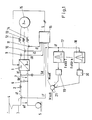
- FIG. 1 shows an inverter with a control and regulating device that is operated on the direct voltage contact wire.
- a capacitor 6 is arranged between the connections of the inverter 1.
- a voltage detection device 7 is provided for detecting the direct voltage Ud between the input terminals of the inverter 1.
- the contact wire voltage between DC contact wire 4 and rail 5 is designated UF.
- the contact wire current determined with the aid of the current detection device 3 is denoted by iF and the direct current flowing into the inverter 1 is denoted by id.
- the three-phase voltage outputs of the inverter 1 are via current detection devices 9 or 10 or 11 for determining the motor currents iR or iS or iT and via chokes 12 or 13 or 14 with a three-phase machine 15 (asynchronous machine) as the driving motor of the rail or local transport vehicle wired.
- a central control and regulating device 16 (including the tax rate) is provided for regulating the inverter 1. This receives the values of the motor currents iR, iS, iT, the direct voltage Ud, the contact wire current iF as well as a modulated torque setpoint Msoll 'on the input side and issues switching commands S on the output side for controlling the inverter valves.
- the contact wire current iF determined via the current detection device 3 is fed to one or more bandpass filters 17.18 connected in parallel, the individual bandpass filters being matched to a different interference frequency fstör1 ... fstörn of an interference current to be suppressed in the contact wire current are.
- the output signal of each bandpass filter 17..18 is fed in phase opposition to a common summation point 21 via its own controller 19..20.
- the torque setpoint Msetpoint is present with a positive sign at this summation point 21.
- the summation point 21 forms the modulated torque setpoint Msoll 'by adding Msoll and the opposite-phase controller output signals and feeds the modulated value to the control and regulating device 16.
- the torque setpoint modulated in this way causes an alternating current component in the contact wire current, which counteracts the causative interference current (active suppression).
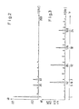
- the stationary motor current spectrum and the stationary DC spectrum are shown, as z. B. occurs when using the device according to DE-OS 34 38 504.
- FIG. 3 shows the effective value of the direct current id as a function of the frequency f (interference frequency) of the interference current.
- the ordinal number of the harmonic of id is also noted.
- the system's interference currents also include e.g. B. caused by control-side defects (amplitudes and / or timing errors) asymmetries in the three-phase voltage system. These lead to current components with a fundamental oscillation frequency, for example.
- Non-system interference currents include mechanical vibrations on the drive side in the bogie travel motor rail area. These lead to amplitude modulation of the contact wire current in the low frequency range (some 10 Hz).
- the non-system interference currents also include parts from the overhead contact line network that can arise from the power generating device, other vehicles or resonance points in the overhead contact line network.
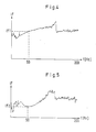
- FIGS. 4 and 5 show peak hold spectra of an acceleration run down to the fundamental frequency range when using the device according to DE-OS 34 38 504.
- a frequency f 50 Hz (interference frequency)
- FIG. 5 shows the effective value of the direct current iF as a function of the frequency f (interference frequency), a 50 Hz suppression according to the device described being used (fstör1 of the bandpass filter 17:50 Hz).
- fstör1 of the bandpass filter 17:50 Hz the frequency f
- iF2 the frequency response of the bandpass filter
- the frequency response of the bandpass filter can be seen with a slope of 18 dB / octave in the range of the interference frequency.
- the attenuation was set to about 6 dB in the present case. This corresponds approximately to the weakening of the strong sixth harmonic of the motor current in the device according to DE-OS 34 38 504, which cannot be arbitrarily weakened for physical reasons (the trajectory of the river area pointer is like a hexagon). If this hexagonal path curve of the river area pointer is replaced by a circular path curve, interference currents can be achieved, as are known from vehicles with active interference suppression via the input actuator.
- the device described only works if the transmission behavior iF / Msoll has a sufficient frequency response.
- a traction motor control implemented with the device according to DE-OS 34 38 504 has this essential requirement.
Landscapes
- Engineering & Computer Science (AREA)
- Life Sciences & Earth Sciences (AREA)
- Sustainable Development (AREA)
- Sustainable Energy (AREA)
- Power Engineering (AREA)
- Transportation (AREA)
- Mechanical Engineering (AREA)
- Electric Propulsion And Braking For Vehicles (AREA)
- Control Of Ac Motors In General (AREA)
- Centrifugal Separators (AREA)
- Control Of Multiple Motors (AREA)
- Control Of Eletrric Generators (AREA)
Priority Applications (1)
| Application Number | Priority Date | Filing Date | Title |
|---|---|---|---|
| AT87116387T ATE55091T1 (de) | 1986-11-14 | 1987-11-06 | Einrichtung zur regelung einer ueber einen wechselrichter gespeisten drehfeldmaschine. |
Applications Claiming Priority (2)
| Application Number | Priority Date | Filing Date | Title |
|---|---|---|---|
| DE3638945 | 1986-11-14 | ||
| DE19863638945 DE3638945A1 (de) | 1986-11-14 | 1986-11-14 | Einrichtung zur regelung einer ueber einen wechselrichter gespeisten drehfeldmaschine |
Publications (3)
| Publication Number | Publication Date |
|---|---|
| EP0267548A2 true EP0267548A2 (fr) | 1988-05-18 |
| EP0267548A3 EP0267548A3 (en) | 1989-02-22 |
| EP0267548B1 EP0267548B1 (fr) | 1990-08-01 |
Family
ID=6313948
Family Applications (1)
| Application Number | Title | Priority Date | Filing Date |
|---|---|---|---|
| EP87116387A Expired - Lifetime EP0267548B1 (fr) | 1986-11-14 | 1987-11-06 | Dispositif pour contrôler d'une machine à champ tournant altimentée par onduleur |
Country Status (4)
| Country | Link |
|---|---|
| EP (1) | EP0267548B1 (fr) |
| JP (1) | JPS63136902A (fr) |
| AT (1) | ATE55091T1 (fr) |
| DE (2) | DE3638945A1 (fr) |
Cited By (5)
| Publication number | Priority date | Publication date | Assignee | Title |
|---|---|---|---|---|
| EP0779701A1 (fr) | 1995-12-14 | 1997-06-18 | Cegelec | Agencement de commande de machine électrique incluant un dispositif de lissage de couple |
| WO2000015456A1 (fr) * | 1998-09-11 | 2000-03-23 | Siemens Aktiengesellschaft | Procede de surveillance et dispositif de surveillance pour un filtre |
| RU2209144C1 (ru) * | 2002-07-04 | 2003-07-27 | ООО "Желдорконсалтинг" | Способ управления тяговым электроприводом |
| WO2005022731A3 (fr) * | 2003-09-03 | 2005-05-12 | Bombardier Transp Gmbh | Transfert de l'energie electrique d'un cote principal a un cote secondaire d'un convertisseur |
| EP4056406A1 (fr) * | 2021-03-12 | 2022-09-14 | Transportation IP Holdings, LLC | Système et procédé de commande pour véhicule |
Families Citing this family (4)
| Publication number | Priority date | Publication date | Assignee | Title |
|---|---|---|---|---|
| DE3931558A1 (de) * | 1989-09-22 | 1990-01-11 | Asea Brown Boveri | Regelkreise |
| DE3940912A1 (de) * | 1989-12-12 | 1991-06-13 | Krupp Maschinentechnik | Energieversorgungseinrichtung fuer das bordrestaurant eines speisewagens |
| DE19638574A1 (de) * | 1996-09-20 | 1998-04-02 | Abb Daimler Benz Transp | Stromversorgungsanordnung für Bahnfahrzeuge mit wenigstens einem gleichspannungsgespeisten, geregelten Stromrichter |
| CZ297154B6 (cs) * | 2004-12-07 | 2006-09-13 | Elcom, A. S. | Zpusob kompenzace ohrozujících proudu emitovanýchz trakcního pohonu silového obvodu hnacího zeleznicního vozidla do kolejového obvodu a zapojení kompenzátoru k provádení tohoto zpusobu |
Family Cites Families (3)
| Publication number | Priority date | Publication date | Assignee | Title |
|---|---|---|---|---|
| JPS57145503A (en) * | 1981-03-04 | 1982-09-08 | Hitachi Ltd | Controlling device of induction motor driven electric motor vehicle |
| DE3438504A1 (de) * | 1984-10-20 | 1986-04-24 | Brown, Boveri & Cie Ag, 6800 Mannheim | Verfahren und einrichtung zur regelung einer drehfeldmaschine |
| FR2576163B1 (fr) * | 1985-01-17 | 1987-02-06 | Alsthom Atlantique | Procede et dispositifs d'attenuation des courants harmoniques perturbateurs renvoyes sur une ligne d'alimentation electrique par un equipement |
-
1986
- 1986-11-14 DE DE19863638945 patent/DE3638945A1/de active Granted
-
1987
- 1987-11-06 DE DE8787116387T patent/DE3764067D1/de not_active Expired - Lifetime
- 1987-11-06 EP EP87116387A patent/EP0267548B1/fr not_active Expired - Lifetime
- 1987-11-06 AT AT87116387T patent/ATE55091T1/de not_active IP Right Cessation
- 1987-11-13 JP JP62285665A patent/JPS63136902A/ja active Pending
Cited By (9)
| Publication number | Priority date | Publication date | Assignee | Title |
|---|---|---|---|---|
| EP0779701A1 (fr) | 1995-12-14 | 1997-06-18 | Cegelec | Agencement de commande de machine électrique incluant un dispositif de lissage de couple |
| FR2742609A1 (fr) * | 1995-12-14 | 1997-06-20 | Cegelec | Agencement de commande de machine electrique incluant un dispositif de lissage de couple |
| US5773944A (en) * | 1995-12-14 | 1998-06-30 | Cegelec | Electric machine control system including a torque smoothing device |
| WO2000015456A1 (fr) * | 1998-09-11 | 2000-03-23 | Siemens Aktiengesellschaft | Procede de surveillance et dispositif de surveillance pour un filtre |
| US6496011B2 (en) | 1998-09-11 | 2002-12-17 | Siemens Aktiengesellschaft | Monitoring method and monitoring device for a filter |
| RU2209144C1 (ru) * | 2002-07-04 | 2003-07-27 | ООО "Желдорконсалтинг" | Способ управления тяговым электроприводом |
| WO2005022731A3 (fr) * | 2003-09-03 | 2005-05-12 | Bombardier Transp Gmbh | Transfert de l'energie electrique d'un cote principal a un cote secondaire d'un convertisseur |
| EP4056406A1 (fr) * | 2021-03-12 | 2022-09-14 | Transportation IP Holdings, LLC | Système et procédé de commande pour véhicule |
| US12344128B2 (en) | 2021-03-12 | 2025-07-01 | Transportation Ip Holdings, Llc | Vehicle control system and method |
Also Published As
| Publication number | Publication date |
|---|---|
| DE3638945A1 (de) | 1988-05-26 |
| EP0267548B1 (fr) | 1990-08-01 |
| ATE55091T1 (de) | 1990-08-15 |
| EP0267548A3 (en) | 1989-02-22 |
| DE3764067D1 (de) | 1990-09-06 |
| DE3638945C2 (fr) | 1989-09-14 |
| JPS63136902A (ja) | 1988-06-09 |
Similar Documents
| Publication | Publication Date | Title |
|---|---|---|
| EP2087583B1 (fr) | Entraînement par traction pour entraîner et freiner électriquement un véhicule sur rails avec correction de charge | |
| EP0267548B1 (fr) | Dispositif pour contrôler d'une machine à champ tournant altimentée par onduleur | |
| DE3817652C2 (fr) | ||
| EP0782784B1 (fr) | Procede de regulation d'un regulateur a quatre quadrants servant de convertisseur de courant du secteur | |
| EP0888922A1 (fr) | Réglage pour l'entraínement d'un moteur asynchrone | |
| DE4434378C1 (de) | Verfahren zur Regelung eines als Netzstromrichter fungierenden Vierquadrantenstellers | |
| DE3218885C2 (de) | Regeleinrichtung für eine Stromrichteranlage mit steuerbarem Halbleitersteller | |
| EP2040954B1 (fr) | Dispositif et procédé d'alimentation de consommateurs dans un véhicule sur rails | |
| DE19537526B4 (de) | Elektrisch betriebenes Fahrzeug, insbesondere Triebfahrzeug | |
| EP3488520A1 (fr) | Système convertisseur et procédé de fonctionnement d'un système convertisseur | |
| DE102015220736A1 (de) | Schienenfahrzeug-Antriebseinheit | |
| EP0093929B1 (fr) | Procédé pour la commande du flux magnétique d'une machine asynchrone et son appareil | |
| EP1017157B1 (fr) | Méthode pour le contrôle d'une portion non harmonique du courant de réseau d'un convertisseur et dispositif pour mettre en oeuvre la méthode | |
| DE102020000126A1 (de) | Antriebssystem, aufweisend einen ersten Umrichter und zumindest einen zweiten Umrichter | |
| DE3724763C2 (fr) | ||
| DE2944334C2 (fr) | ||
| DE3718713C2 (fr) | ||
| AT400699B (de) | Antriebsanordnung für ein schienenfahrzeug | |
| DE1405691A1 (de) | Anordnung zur UEbertragung von Befehlen oder Informationen | |
| DE19630302A1 (de) | Fahrortabhängige Geschwindigkeitssteuerung von Fahrzeugen mit Drehstromantrieb durch frequenzgesteuerte Umrichter | |
| EP0170289A2 (fr) | Dispositif d'alimentation pour un moteur à courant continu d'un train à partir d'une source en courant alternatif | |
| DE2444251A1 (de) | Gleisstromkreis, insbesondere fuer gleichstrombahnen mit chopper-gesteuerten triebfahrzeugen | |
| DD298184A5 (de) | Schaltungsanordnung bei einem gesteuerten stromrichter | |
| EP0973247A1 (fr) | Translation des motifs d'impulsions en fonction de la puissance | |
| DE19828753B4 (de) | Verfahren zur Optimierung der Kraftschlußregelung von elektrischen Schienenfahrzeugen |
Legal Events
| Date | Code | Title | Description |
|---|---|---|---|
| PUAI | Public reference made under article 153(3) epc to a published international application that has entered the european phase |
Free format text: ORIGINAL CODE: 0009012 |
|
| AK | Designated contracting states |
Kind code of ref document: A2 Designated state(s): AT CH DE FR GB IT LI SE |
|
| PUAL | Search report despatched |
Free format text: ORIGINAL CODE: 0009013 |
|
| AK | Designated contracting states |
Kind code of ref document: A3 Designated state(s): AT CH DE FR GB IT LI SE |
|
| RHK1 | Main classification (correction) |
Ipc: B60L 9/22 |
|
| 17P | Request for examination filed |
Effective date: 19890330 |
|
| 17Q | First examination report despatched |
Effective date: 19890718 |
|
| GRAA | (expected) grant |
Free format text: ORIGINAL CODE: 0009210 |
|
| AK | Designated contracting states |
Kind code of ref document: B1 Designated state(s): AT CH DE FR GB IT LI SE |
|
| REF | Corresponds to: |
Ref document number: 55091 Country of ref document: AT Date of ref document: 19900815 Kind code of ref document: T |
|
| ITF | It: translation for a ep patent filed | ||
| GBT | Gb: translation of ep patent filed (gb section 77(6)(a)/1977) | ||
| REF | Corresponds to: |
Ref document number: 3764067 Country of ref document: DE Date of ref document: 19900906 |
|
| REG | Reference to a national code |
Ref country code: CH Ref legal event code: PUE Owner name: ASEA BROWN BOVERI AKTIENGESELLSCHAFT |
|
| RAP2 | Party data changed (patent owner data changed or rights of a patent transferred) |
Owner name: ASEA BROWN BOVERI AKTIENGESELLSCHAFT |
|
| ET | Fr: translation filed | ||
| PLBE | No opposition filed within time limit |
Free format text: ORIGINAL CODE: 0009261 |
|
| STAA | Information on the status of an ep patent application or granted ep patent |
Free format text: STATUS: NO OPPOSITION FILED WITHIN TIME LIMIT |
|
| 26N | No opposition filed | ||
| ITTA | It: last paid annual fee | ||
| PGFP | Annual fee paid to national office [announced via postgrant information from national office to epo] |
Ref country code: GB Payment date: 19931020 Year of fee payment: 7 Ref country code: AT Payment date: 19931020 Year of fee payment: 7 |
|
| PGFP | Annual fee paid to national office [announced via postgrant information from national office to epo] |
Ref country code: SE Payment date: 19931102 Year of fee payment: 7 |
|
| PGFP | Annual fee paid to national office [announced via postgrant information from national office to epo] |
Ref country code: FR Payment date: 19931103 Year of fee payment: 7 Ref country code: CH Payment date: 19931103 Year of fee payment: 7 |
|
| PG25 | Lapsed in a contracting state [announced via postgrant information from national office to epo] |
Ref country code: GB Effective date: 19941106 Ref country code: AT Effective date: 19941106 |
|
| PG25 | Lapsed in a contracting state [announced via postgrant information from national office to epo] |
Ref country code: SE Effective date: 19941107 |
|
| PG25 | Lapsed in a contracting state [announced via postgrant information from national office to epo] |
Ref country code: LI Effective date: 19941130 Ref country code: CH Effective date: 19941130 |
|
| EAL | Se: european patent in force in sweden |
Ref document number: 87116387.9 |
|
| GBPC | Gb: european patent ceased through non-payment of renewal fee |
Effective date: 19941106 |
|
| PG25 | Lapsed in a contracting state [announced via postgrant information from national office to epo] |
Ref country code: FR Effective date: 19950731 |
|
| REG | Reference to a national code |
Ref country code: CH Ref legal event code: PL |
|
| EUG | Se: european patent has lapsed |
Ref document number: 87116387.9 |
|
| REG | Reference to a national code |
Ref country code: FR Ref legal event code: ST |
|
| PGFP | Annual fee paid to national office [announced via postgrant information from national office to epo] |
Ref country code: DE Payment date: 20031103 Year of fee payment: 17 |
|
| PG25 | Lapsed in a contracting state [announced via postgrant information from national office to epo] |
Ref country code: DE Free format text: LAPSE BECAUSE OF NON-PAYMENT OF DUE FEES Effective date: 20050601 |
|
| PG25 | Lapsed in a contracting state [announced via postgrant information from national office to epo] |
Ref country code: IT Free format text: LAPSE BECAUSE OF NON-PAYMENT OF DUE FEES;WARNING: LAPSES OF ITALIAN PATENTS WITH EFFECTIVE DATE BEFORE 2007 MAY HAVE OCCURRED AT ANY TIME BEFORE 2007. THE CORRECT EFFECTIVE DATE MAY BE DIFFERENT FROM THE ONE RECORDED. Effective date: 20051106 |