EP0267638A1 - Erdölbohrlochsicherheitsventil für die Verwendung beim künstlichen Fördern - Google Patents
Erdölbohrlochsicherheitsventil für die Verwendung beim künstlichen Fördern Download PDFInfo
- Publication number
- EP0267638A1 EP0267638A1 EP87201966A EP87201966A EP0267638A1 EP 0267638 A1 EP0267638 A1 EP 0267638A1 EP 87201966 A EP87201966 A EP 87201966A EP 87201966 A EP87201966 A EP 87201966A EP 0267638 A1 EP0267638 A1 EP 0267638A1
- Authority
- EP
- European Patent Office
- Prior art keywords
- sleeve
- slide
- valve
- valve body
- safety valve
- Prior art date
- Legal status (The legal status is an assumption and is not a legal conclusion. Google has not performed a legal analysis and makes no representation as to the accuracy of the status listed.)
- Granted
Links
- 239000003129 oil well Substances 0.000 title abstract description 8
- 239000012530 fluid Substances 0.000 claims abstract description 63
- 238000004873 anchoring Methods 0.000 claims abstract description 42
- 238000006073 displacement reaction Methods 0.000 claims abstract description 10
- 238000007789 sealing Methods 0.000 claims abstract description 4
- 241000282472 Canis lupus familiaris Species 0.000 claims description 40
- 238000004519 manufacturing process Methods 0.000 claims description 16
- 230000002093 peripheral effect Effects 0.000 claims description 11
- 238000002347 injection Methods 0.000 claims description 9
- 239000007924 injection Substances 0.000 claims description 9
- 230000000694 effects Effects 0.000 claims description 6
- 230000000903 blocking effect Effects 0.000 claims description 4
- 238000000926 separation method Methods 0.000 claims description 3
- 230000008878 coupling Effects 0.000 claims 1
- 238000010168 coupling process Methods 0.000 claims 1
- 238000005859 coupling reaction Methods 0.000 claims 1
- 239000000463 material Substances 0.000 claims 1
- 239000003208 petroleum Substances 0.000 claims 1
- 239000007789 gas Substances 0.000 description 12
- 238000009434 installation Methods 0.000 description 9
- 230000008901 benefit Effects 0.000 description 4
- 230000009471 action Effects 0.000 description 3
- 230000007547 defect Effects 0.000 description 3
- 238000000034 method Methods 0.000 description 3
- 238000010926 purge Methods 0.000 description 3
- 230000006866 deterioration Effects 0.000 description 2
- 238000000605 extraction Methods 0.000 description 2
- 238000007667 floating Methods 0.000 description 2
- 239000007788 liquid Substances 0.000 description 2
- 230000001050 lubricating effect Effects 0.000 description 2
- 125000006850 spacer group Chemical group 0.000 description 2
- 239000004952 Polyamide Substances 0.000 description 1
- 229910000831 Steel Inorganic materials 0.000 description 1
- 230000006978 adaptation Effects 0.000 description 1
- 230000000295 complement effect Effects 0.000 description 1
- 230000007797 corrosion Effects 0.000 description 1
- 238000005260 corrosion Methods 0.000 description 1
- 230000008021 deposition Effects 0.000 description 1
- 230000001747 exhibiting effect Effects 0.000 description 1
- 230000002349 favourable effect Effects 0.000 description 1
- 238000007654 immersion Methods 0.000 description 1
- 230000006872 improvement Effects 0.000 description 1
- 229920002647 polyamide Polymers 0.000 description 1
- 238000003825 pressing Methods 0.000 description 1
- 238000005086 pumping Methods 0.000 description 1
- 230000008439 repair process Effects 0.000 description 1
- 239000010959 steel Substances 0.000 description 1
- 229920002994 synthetic fiber Polymers 0.000 description 1
- 230000009466 transformation Effects 0.000 description 1
- 238000011144 upstream manufacturing Methods 0.000 description 1
- 230000002747 voluntary effect Effects 0.000 description 1
- XLYOFNOQVPJJNP-UHFFFAOYSA-N water Substances O XLYOFNOQVPJJNP-UHFFFAOYSA-N 0.000 description 1
- 238000003466 welding Methods 0.000 description 1
Images
Classifications
-
- E—FIXED CONSTRUCTIONS
- E21—EARTH OR ROCK DRILLING; MINING
- E21B—EARTH OR ROCK DRILLING; OBTAINING OIL, GAS, WATER, SOLUBLE OR MELTABLE MATERIALS OR A SLURRY OF MINERALS FROM WELLS
- E21B34/00—Valve arrangements for boreholes or wells
- E21B34/06—Valve arrangements for boreholes or wells in wells
- E21B34/10—Valve arrangements for boreholes or wells in wells operated by control fluid supplied from outside the borehole
- E21B34/105—Valve arrangements for boreholes or wells in wells operated by control fluid supplied from outside the borehole retrievable, e.g. wire line retrievable, i.e. with an element which can be landed into a landing-nipple provided with a passage for control fluid
-
- E—FIXED CONSTRUCTIONS
- E21—EARTH OR ROCK DRILLING; MINING
- E21B—EARTH OR ROCK DRILLING; OBTAINING OIL, GAS, WATER, SOLUBLE OR MELTABLE MATERIALS OR A SLURRY OF MINERALS FROM WELLS
- E21B43/00—Methods or apparatus for obtaining oil, gas, water, soluble or meltable materials or a slurry of minerals from wells
- E21B43/12—Methods or apparatus for controlling the flow of the obtained fluid to or in wells
- E21B43/121—Lifting well fluids
Definitions
- the invention relates to a safety valve intended to be inserted into an oil well production tube in order to ensure opening or closing, while allowing operation in artificial flow by injection of a pressurized fluid, says injected fluid.
- the safety valves for oil wells have the function of automatically stopping the production of effluent if an incident occurs at the head of the well or downstream from it. They are hydraulically controlled upon opening from the surface and are closed automatically by means of a powerful return spring as soon as a hydraulic pressure drop, commanded or accidental, occurs. These valves have been the subject of numerous development and improvement studies, and their use has become widespread, in particular in offshore eruptive wells.
- these valves are anchored in a receptacle sleeve housed in the production tube; anchoring is carried out by means of a system of mechanical dogs capable of undergoing a radial displacement which cause them to enter an anchoring groove of the receptacle sleeve: these dogs are then locked in their anchoring position by means of a spring which pushes a locking ring inside said dogs.
- these dogs When these dogs are correctly positioned and locked, they provide an anchorage benefiting from good qualities of mechanical resistance.
- a pressurized fluid generally a gas
- the anchor dogs and their locking system have too large a radial dimension to allow the passage of an internal injection tube of sufficient diameter.
- FR patent No. 2,536,783 and its certificate of addition No. 2,555,246 have a valve structure modified with respect to traditional valves; in this new valve, the locking is achieved by means of an elastic ring which is held radially retracted by a system of collar and keys when the valve is lowered and which is released at the end of the descent when the ring reaches the level of the anchoring groove of the receptacle sleeve.
- This system allows the installation of an internal gas injection tube, but has the very serious defect of being extremely fragile: the elastic ring breaks very frequently either during the installation of the valve, or during of its unlocking, and each break causes very serious practical difficulties of repair and significant risks for personnel.
- the installation is carried out blind, without guarantee of correct anchoring.
- the present invention proposes to provide an improved safety valve, capable of authorizing operation in artificial flow, without exhibiting the above-mentioned defects of known valves.
- An object of the invention is in particular to provide a valve for an artificial flow well, benefiting from a very robust anchoring system and making it possible to guarantee correct anchoring during installation.
- Another objective is to authorize easy unlocking and raising of the valve, without risk of breakage.
- Another objective is to artificial valve manufactorune wells which enjoys most of the benefits of improved units for eruptive wells described in French applications 86.11417 and No. 86.11418 filed on behalf of the applicant on 07/29/1986.
- Another objective is to allow easy transformation of the valves in order to adapt them to the types of wells concerned: wells with artificial flow or eruptive wells.
- valve according to the invention is described assuming it is in place in an oil well, the terms "high”, “low”, “upper”, “lower”, “base”, “head” ... referring to this position.
- the safety valve targeted by the invention is intended to be inserted into an oil well production tube in order to ensure opening or closing, while allowing operation in artificial flow by injecting a fluid under pressure, said injected fluid;
- this valve comprises in combination: - a valve body of generally tubular shape, - a movable shutter valve, located in the lower part of said body and urged towards its closed position, - a tubular slide arranged to be able to slide longitudinally inside the valve body in order to generate in its downward movement the opening of the shutter valve, a return spring disposed in an annular housing located between the slide and the valve body, so as to urge said slide towards a high position corresponding to the closing of the shutter valve, means of hydraulic displacement of the slide downward, comprising an inlet for control fluid through the valve body and a sealed volume between the slide and the body intended to receive the control fluid, the slide having a difference in section subjected to the pressure of the fluid contained in said sealed volume so as to undergo a downward force when said volume is under pressure, - seals,
- a mechanical anchoring system with hydraulic stress located in the upper part of the valve body below the upper attachment sleeve and adapted to allow the valve body to be secured in the receptacle sleeve housed in the production tube , said system comprising means for stopping the valve body in said sleeve-receptacle, dogs movable radially so as to be able to penetrate, in the stop position, into an anchoring groove in the sleeve-receptacle, and mechanical means for operation and locking of dogs, arranged to be subjected to the pressure of the control fluid contained in the aforementioned sealed volume and adapted to repel radially said dogs and lock them in the anchoring groove under the effect of said pressure.
- these operating and locking means comprise: . a tubular sliding piston, mounted so as to be able to move freely in the valve body around the upper part of the slide, between a low stop position and a high stop position in the absence of any mechanical blocking on the height of its movement, said sliding piston being arranged to present a surface subjected to the pressure of the control fluid contained in the sealed volume so as to undergo an upward force when said volume is under pressure, .
- an interlocking locking sleeve slidingly mounted in the valve body above the sliding piston but independently of the latter so that said sliding piston can only exert on said bushing an upward thrust without the possibility of driving downwards, said bushing having a peripheral cam adapted to come into correspondence with the dogs and push them radially into the high position of the sliding piston.
- the valve according to the invention comprises an improved mooring system of the type fitted to the valve described in patent application FR No. 86.11418, which combines with an adaptation of the structure of said valve to permit injection of '' a pressurized fluid in order to lighten the effluent column and allow operation in artificial flow.
- the dogs are made up of robust mechanical parts, not subject to the risk of breakage, while the hydraulic control system for locking them (by means of the control fluid acting on the wandering piston) has a small radial size allowing to release the central internal volume of the valve and to house the internal tube for passage of the injected fluid, while preserving between this tube and the slide an annular space sufficient for the passage of the effluent.
- This internal tube is carried by the slide and follows the movements thereof; in the upper part, it slides tightly in the upper attachment sleeve so that the continuity of passage of the injected fluid is permanently ensured at this level; in the lower part, the tube can either come tightly connect with the lower hooking sleeve to ensure the continuity of passage of the injected fluid when the slide is in the low position (valve open), or retract upwards to allow the valve to close when the slide is in the high position (valve closed).
- valve according to the invention is thus able to provide, for a well with an artificial flow, the same safety features as the eruptive well valve described in the abovementioned application; in addition it benefits from the various advantages of this valve: reduced risks of corrosion and deposits, satisfactory anchoring guarantee, ...
- the valve body consists of several tubular parts screwed one in the extension of the other by right-hand threads and comprises, at the top, a latch body composed of two screwed tubular parts l '' as an extension of the other by threads on the left: the lower part contains the dogs and is screwed onto the lower contiguous section of the valve body (by threads on the right), while the upper part is partly fitted high of a head for fixing the upper hanging sleeve.
- valve can be extracted from the well by implementing a very simple unlocking and undocking procedure: it suffices to unscrew the two parts of the lock body (by an appropriate rotation of the train of upper tubes) and reassemble the assembly by pulling on this train of tubes.
- the structure of the valve is preferably consistent with that described in application FR No. 86.11417.
- the seals located on either side of the inlet of the control fluid are advantageously positioned immediately below and above said fluid inlet, the anchoring system being located above the upper lining, while the return spring is positioned below the lower lining in an annular housing formed by a part of the sealed volume intended to receive the control fluid.
- Such a structure allows complete drainage of the sealed volume containing the control fluid during pressurization, while the arrangement of the return spring guarantees total immersion of the latter in the control fluid.
- This spring is sheltered from the attacks of effluent or corrosive gases and can be made of a steel with high modulus of elasticity favorable to obtaining a high restoring force, stable over time.
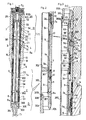
- the safety valve shown by way of example in the figures is intended to equip an oil well production tube called to work at an artificial flow rate by means of an injection of gas under pressure.
- the production tube has a receptacle sleeve 1 provided with a control fluid inlet line 1a and an anchoring groove 1b, the edges of which are in the form of a conical ramp (face lower conical 1bi and upper conical face 1bs).
- This valve advantageously the general structure of the improved valve described in patent application FR No. 86.11417 filed by the applicant; it comprises a valve body of generally tubular shape, consisting of several tubular parts secured to each other: upper lock body 2, upper seal holder 3 carrying an upper seal 15, tubular spacer 4, ring-nut of locking 5, spring jacket 6 having an upper heel 6a carrying a lower seal 16, lower sleeve 7, obturator body 8.
- the seal carrier 3 and the spacer 4 are pierced with holes 3a, 4a for the passage of the control fluid from line 1a.
- the seals, upper 15 and lower 16 are positioned immediately above and below the lumen 4a.
- the various tubular parts forming the valve body are secured by screwing one in the extension of the other by means of threads on the right.
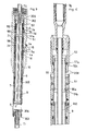
- a tubular slide 9 able to move longitudinally in the valve body, between a low position (corresponding to the opening) shown in Figure 1 and a high position (corresponding to the closure) shown in Figure 4.
- This slide is returned to its upper position by a return spring 10 which is housed, below the linings 15 and 16, in a sealed annular volume delimited by the external face of the slide 9 and the inner face of the jacket 6.
- the spring 10 extends between, on the one hand, an upper support constituted by a ring-nut 19 screwed around the slide 9 (with the interposition of an auxiliary socket 18 having the same function as the socket 18 of the valve described in application 86.11421), on the other hand, a lower socket 20 mounted to slide around said slide.
- a lower stop 9c limits the downward stroke of said bush relative to the slide (this stop 9c is formed by a shoulder formed on the external surface of the slide).
- this sleeve 20 is applied against a shoulder 7a provided inside the valve body (shoulder formed by the upper edge of the sleeve 7 screwed into the spring jacket 6).
- This slide is hydraulically controlled downwards by the control fluid arriving by the line la when the latter is pressurized.
- This control fluid is formed by a lubricating liquid; when pressurized, it passes through the ports 4a and 3a, is stopped at the valve body / sleeve-receptacle interface by the seals 15 and 16 located on either side of said ports and comes fill a sealed volume located between the slide and the valve body.
- This tight volume is limited, at the slide / valve body interface: . on the one hand, by an upper seal 21 arranged above the inlet of the control fluid in a groove of a sliding piston 58 which is part of the anchoring system described below (a complementary seal 24 being provided on the external surface of said sliding piston to ensure sealing at the interface of the latter and of the valve body), . on the other hand, by a lower seal 22 arranged in a groove below and in the vicinity of the lower end of the return spring 10, in abutment against the slide.
- the slide 9 has, at the lower seal 22, a larger section than that existing at the upper seal 21 so that the pressure control fluid acts downward on said slide through this difference in section.
- the shutter body 8 comprises a movable shutter member, constituted by a valve 11 which is articulated on said body so as to be able to pivot between a retracted open position on the side (FIG. 1 ) and a closed position where said valve closes the valve body by pressing against a seal carried by it ( Figure 4).
- the valve 11 is returned to the closed position by a spring 12 disposed around its axis of articulation.
- this blocking member may be of the type described in FR No. 86.11421 filed by the applicant.
- the slider 9 Under the effect of the hydraulic control, the slider 9 is moved to its low position until it comes into abutment with a shoulder 8a of the shutter body: said slider then pushes the shutter member 11 and keeps it in the open position.
- the return spring 10 When the pressure of the control fluid accidentally or voluntarily drops, the return spring 10 generates a displacement of the slider upwards, until its high position where it is set back in the sleeve 7 (FIG. 4). The shutter member 11 is then released and closes under the action of its own spring 12.
- the slide 9 carries a concentric internal tube 300 for the passage of a pressurized gas which is injected in order to lighten the column of effluent and produce an artificial flow.
- the slide 9 is formed of two sections screwed one after the other: an upper section 9s extending over most of its height and a lower section 9i ( Figure 2); the upper section 9s carries in the lower part a notch 9e which is closed by the lower section 9i when the latter is screwed at the end of said upper section.
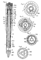
- This notch 9e can thus contain and trap a ring 301 which can be seen on the cross section 7.
- This ring concentric with the slide 9 and the tube 300, is fixed to the peripheral ends of radial fins 302, in the example three in number, distributed around the inner tube 300; the central ends of these fins are fixed by welding to the tube 300.
- each fin 302 is extended by a profiled end piece so as to reduce the pressure drop and the turbulence they cause in the effluent, which is called to flow from bottom to top in the annular space between the internal tube 300 and the slide 9.
- the internal tube 300 thus moves with the slide 9 which carries it, between a low position (open position shown in Figure 1) and a high position (closed position shown in Figure 4). Its length is provided so that, in the low position, its lower end called the connection 300i is located slightly below the level of the shutter valve 11 and that, in its high position, this lower connection end retracts above the level of said valve.
- said lower connection end 300i is coupled with a lower hooking sleeve 303 whose role is to maintain a train of lower tubes (shown in Ti in broken lines in FIG. 1). ) inside which the injected gas passes.
- the lower attachment sleeve 303 is provided at its lower part with a right-hand thread, around which the last tube Ti of the lower train is screwed.
- the attachment sleeve 303 is secured to the base of the valve body on the shutter body 8, by means of radial arms 304, three in example (FIG. 8), which are distributed around said sleeve and whose peripheral ends are integral with an annular base 305 forming the valve nose.
- this part 305 is screwed onto the shutter body (by a right-hand thread). If necessary, it could be made in one piece with this body (the body 8 / part 305 / arm 304 / sleeve 303 assembly being constituted by a single piece from the foundry).
- the lower attachment sleeve 303 is equipped at its upper end with an added conical bearing 306, formed on a short section of tube screwed into the sleeve 303 with the interposition of a seal 307.
- This section of tube is a synthetic material such as polyamide, capable of ensuring a seal in contact with the internal tube 300 when the latter is in the low position; the lower connection end 300i of said internal tube is cut to a conjugate conical shape of the bearing 306 in order to make the sealed connection.
- the valve is equipped with a mechanical anchoring system with hydraulic stress, which essentially comprises the lock body 2, anchoring dogs 54, a locking sleeve 55 and a sliding piston 58 .
- the lock body is screwed by a right-hand thread 50 on the contiguous section of the valve body (constituted by the upper seal holder 3). Its lower end 51c internally forms a projection intended to serve as a stop for the sliding piston 58 in the high position.
- This lock body is composed of two tubular parts, lower 51 and upper 52, which are screwed in the extension of one another by left-hand threads 308. These threads which are of not opposite to that of all the others valve threads allow by a clockwise rotation to release the two parts 51 and 52 in order to reassemble the valve, as will be seen below.
- the lower part 51 is provided with floating dogs such as 54, which are housed in guide lights thereof.
- these dogs are four in number distributed around said part.
- Each dog formed by a die is a mechanical part compact, without risk of breakage, and has upper and lower external chamfers and lower internal chamfers, so as to be able to play radially when the locking sleeve 55 or the receptacle sleeve 1 comes to bear against one of these chamfers.
- shoulders 54a provided laterally inside each dog, prevent complete exhaust to the outside of each dog by coming into abutment against the part 51 of the lock body.
- Each dog can thus project from the lock body as shown in Figures 1 and 6 (anchoring position) or on the contrary retract therein (as shown in Figures 9 or 10).
- the lower part 51 of the lock body has a stop shoulder 51a, which is located below and near the dogs 54.
- This shoulder has the shape of a conical ramp oriented downwards, so as to come into contact of the conical underside 1bi of the anchoring groove 1b when the valve is lowered into the receptacle sleeve 1.
- the lock body has, above this shoulder 51a, a slightly larger diameter than below the latter, the bore of the receptacle sleeve 1 having conjugate shapes.
- the lower part 51 of the lock body is internally provided below the level of the dogs, with a hooking shoulder 51b having the shape of a conical ramp oriented downwards. As will be seen below, this shoulder allows the locking sleeve 55 to be hooked to the part 51 in the event of separation by unscrewing the parts 51 and 52.
- the upper part 52 also includes an internal face 52b which has the form of a conical ramp oriented downwards, adapted to serve as an extreme stop for the locking sleeve 55.
- the upper part 52 finally comprises an internal shoulder 52c which has the shape of a ramp conical oriented upwards, in order to allow said upper part 52 to be hooked onto the locking sleeve 55 after unscrewing the parts 51 and 52.
- Said locking sleeve 55 in equipression is slidably mounted in the lock body with interposition of a braking joint 59 at the interface sleeve / lower part 51; the sleeve is independent of the wandering piston 58 which can only exert on it an upward thrust.
- Said locking sleeve 55 has a peripheral cam 56 which is adapted to push the dogs 54 outward radially when it reaches their level.
- This cam 56 has an upper face 56a, which has the shape of a conical ramp oriented upwards, so as to be able to repel the dogs 54 when it comes into contact with them.
- this upper face 56a limits the stroke of the socket 55 by coming, if necessary, into abutment against the internal face 52b of the upper part 52.
- the locking sleeve 55 is further provided with a hooking shoulder 55a, located below the level of its cam 56 and conjugated with the hooking shoulder 51b of the part 51 so as to be able to cooperate with the latter.
- the locking sleeve 55 is externally provided in the upper part with a peripheral attachment 57, constituted in the example by a ring screwed around the latter.
- This ring has a conical lower face 57a, adapted to be able to come into contact with the internal shoulder 52c of the upper part 52 of the lock body, with a view to attaching said upper part to said sleeve after unscrewing the parts 51 and 52.
- the sliding piston 58 which is called upon to move the locking sleeve 55 towards its high anchoring position is formed by a section of tube, adapted to be able to slide freely in leaktight manner between the valve body (upper part of the seal holder 3) and the upper end of the slide 9.
- This sliding piston 58 is provided with the seals already mentioned, internal 21 at the slide / piston-sliding interface, and external 24 at the piston-sliding / valve body interface; these seals which limit in the upper part the sealed volume containing the control fluid are of different diameters so as to define a surface by which the sliding piston is subjected to the pressure of the control fluid in order to cause its upward movement . It should be noted that the sliding piston 58 is free to slide under the effect of hydraulic pressures in the absence of any mechanical blocking.
- the control fluid acts first on the sliding piston 58 to tend to move it upwards from a low position where it is in abutment against a shoulder 3b of the seal carrier 3 ( Figure 4) to an upper position where said sliding piston abuts against the projection 51c formed by the lower end of the part 51 ( Figures 1 and 3).
- the sliding piston pushes the locking sleeve 55 causing the cam 56 of the latter to radially maneuver the dogs 54 and to lock them.
- control fluid acts on the slide 9 to tend to move it downwards, from its high closed position (FIG. 4) where the nut ring 19 comes into upper abutment against the heel 6a of the spring jacket 6, towards a low open position (FIG. 1) where said slide comes into abutment against the shoulder 8a of the closure body 8.
- the internal tube 300 which allows the injection of gas under pressure penetrates at the top into an upper attachment sleeve 309 which has a bore 309a provided with a seal 310, calibrated to allow leaktight sliding of the upper end of said internal tube 300.
- the length of tube 300 is such that its upper end remains permanently sealed in this bore whatever its high or low position.
- the sleeve is tapped on the right to allow the first tube Ts of a train of upper tubes to be screwed into it (broken lines in FIG. 1).
- the upper attachment sleeve 309 is fixed at the head of the valve body, on the upper part 52 of the lock body, by radial arms 311, in the example three in number, distributed around said sleeve (FIG. 5).
- the peripheral end of these arms is integral with an annular fixing head 313 screwed by threads on the right on the upper part 52.
- valve being depressurized, its slide 9 is in the high position by the action of the return spring 10; the internal tube 300 secured to the slide 9 is itself in the high position.
- the valve 11 is closed.
- the sliding piston 58 and the locking sleeve 55 are in the low position, the dogs 54 being free to fade.
- a train of lower tubes Ti is first lowered into the well in the traditional way using conventional jaw tools.
- the valve is screwed by its lower anchoring sleeve 303 on the upper end of the train of lower tubes; the upper anchoring sleeve 309 is then screwed onto the lower end of another train of tubes Ts and the assembly is lowered using conventional jaw tools.
- the upper tube train Ts generally has a length of the order of 100 to 150 meters.
- the valve enters the receptacle sleeve 1 of the well production tube; the commitment effort of fittings 15 and 16 is overcome by the weight of the lower tube train (several tonnes).
- the dogs 54 of the valve which are floating, are erased at the inlet of the receptacle sleeve.
- the control fluid circuit is then pressurized; the oil enters the sealed volume described above and rises in pressure.
- the sliding piston 58 of the valve is subjected to an upward force and rises by pushing the locking sleeve 55 to its high position. During its movement, the sleeve radially maneuvers the dogs 54 and locks them inside the anchoring groove 1b.
- the valve is at this time anchored in the position shown in FIG. 4 (with the exception, however, of the sliding piston which is in the high position).
- the internal tube 300 descends with the slide 9 and, at the end of the lower stroke, comes to cooperate with the conical bearing 306 of the lower anchoring sleeve 303, while in the upper part, the upper end of said internal tube has slid in the upper anchoring sleeve 309 remaining tightly engaged therein.
- the valve is open and the continuity of the injected fluid circuit is ensured.
- the valve of the invention therefore offers the ability to ensure, at each installation, that the anchoring has been correctly obtained, poor anchoring can come from multiple causes: deterioration of the seals 15 and 16 in progress lowering or deterioration of the receptacle sleeve 1 at said linings (preventing pressurization of the control fluid), deposition due to the effluent in the anchoring groove 1b, (preventing the dogs from leaving 54) ...
- valve once properly anchored in the oil well can be closed in a conventional manner by a voluntary or accidental purging of its hydraulic control line and stopping of the injected gas. It then comes into the position of FIG. 4.
- the return spring 10 has caused an displacement upwards of the slide 9 and of the internal tube 300 which is linked to it, releasing the shutter member 11 which closes under the action of its own spring 12 aided by the pressure of the well (pressurized by the gas already injected).
- the upstream pressure from the well is applied to the entire section of the valve; the dogs 54 of the valve then come to apply against the conical upper face 1bs of the anchoring groove 1b, which conditions a locking effect of the sleeve 55 all the more powerful as the pressure of the well is high: the valve has self-locking proportional to the pressure of the well.
- the valve is reopened, first by injecting pressurized gas into the upper tubes Ts and internal tube 300 in order to balance the pressure on either side of the valve, then putting the hydraulic control line back under pressure: the sliding piston 58 rises against the sleeve 55 and against its stop 51c and the opening occurs as previously explained by displacement of the slide 9 and the inner tube 300 downwards under the pressure of the control fluid.
- the hydraulic control line being purged and the gas injection stopped, the well is put in safety, that is to say in the impossibility of debiting (thanks to a preliminary balancing by pumping water).
- the upper train of tubes is then caused to turn to the right by standard keys so as to unscrew the left-hand thread 308 which connects the upper part 52 of the lock body and the lower part 51.
- this locking sleeve 55 rises until its shoulder 55a comes to bear against the shoulder 51b of the lower part of the lock body.
- the dogs 54 are then released and can fade inwards: the continuation of the traction causes the valve to rise up to the disengagement of the seals 15 and 16, the valve then being able to be raised to the surface.
Landscapes
- Life Sciences & Earth Sciences (AREA)
- Engineering & Computer Science (AREA)
- Geology (AREA)
- Mining & Mineral Resources (AREA)
- Physics & Mathematics (AREA)
- Environmental & Geological Engineering (AREA)
- Fluid Mechanics (AREA)
- General Life Sciences & Earth Sciences (AREA)
- Geochemistry & Mineralogy (AREA)
- Safety Valves (AREA)
- Lift Valve (AREA)
Applications Claiming Priority (2)
| Application Number | Priority Date | Filing Date | Title |
|---|---|---|---|
| FR8614503 | 1986-10-16 | ||
| FR8614503A FR2605381B1 (fr) | 1986-10-16 | 1986-10-16 | Vanne de securite pour puits petrolier, autorisant un fonctionnement en debit artificiel |
Publications (2)
| Publication Number | Publication Date |
|---|---|
| EP0267638A1 true EP0267638A1 (de) | 1988-05-18 |
| EP0267638B1 EP0267638B1 (de) | 1990-07-18 |
Family
ID=9339973
Family Applications (1)
| Application Number | Title | Priority Date | Filing Date |
|---|---|---|---|
| EP87201966A Expired - Lifetime EP0267638B1 (de) | 1986-10-16 | 1987-10-13 | Erdölbohrlochsicherheitsventil für die Verwendung beim künstlichen Fördern |
Country Status (5)
| Country | Link |
|---|---|
| US (1) | US4836287A (de) |
| EP (1) | EP0267638B1 (de) |
| CA (1) | CA1330756C (de) |
| DE (1) | DE3763801D1 (de) |
| FR (1) | FR2605381B1 (de) |
Cited By (1)
| Publication number | Priority date | Publication date | Assignee | Title |
|---|---|---|---|---|
| EP0782123A1 (de) * | 1995-12-27 | 1997-07-02 | Canon Kabushiki Kaisha | Flüssigkristalleinrichtung und Steuerverfahren zur Verhinderung des Vergelbungsphänomens |
Families Citing this family (13)
| Publication number | Priority date | Publication date | Assignee | Title |
|---|---|---|---|---|
| FR2634819A1 (fr) * | 1988-07-29 | 1990-02-02 | Merip Oil Tools Int | Vanne de securite pour puits petrolier destinee notamment a etre inseree dans un manchon receptacle sans epaulement d'arret |
| FR2643127B1 (fr) * | 1989-02-16 | 1991-07-05 | Merip Oil Tools Int | Vanne de securite pour puits petrolier du type autorisant un fonctionnement en debit artificiel, et procede de deverrouillage de ladite vanne |
| US5617918A (en) * | 1992-08-24 | 1997-04-08 | Halliburton Company | Wellbore lock system and method of use |
| AU1090499A (en) * | 1997-10-17 | 1999-05-10 | Camco International, Inc. | Equalizing subsurface safety valve with injection system |
| AU4926799A (en) * | 1998-07-21 | 2000-02-14 | Gas & Oil Associates Limited | Method and apparatus for conveying fluids, particularly useful with respect to oil wells |
| US7779925B2 (en) * | 2004-02-13 | 2010-08-24 | Weatherford/Lamb, Inc. | Seal assembly energized with floating pistons |
| GB2435059B (en) * | 2006-02-08 | 2008-05-07 | Pilot Drilling Control Ltd | A Drill-String Connector |
| GB2457288A (en) * | 2008-02-08 | 2009-08-12 | Pilot Drilling Control Ltd | A drillstring connection valve |
| BRPI0821391B1 (pt) * | 2007-12-20 | 2019-02-12 | Cameron Technologies Limited | Tampão de manobra de tubulação sob pressão, ferramenta de manobra de tubulação sob pressão e método associado |
| US7775291B2 (en) * | 2008-05-29 | 2010-08-17 | Weatherford/Lamb, Inc. | Retrievable surface controlled subsurface safety valve |
| US8100181B2 (en) | 2008-05-29 | 2012-01-24 | Weatherford/Lamb, Inc. | Surface controlled subsurface safety valve having integral pack-off |
| US8479828B2 (en) | 2010-05-13 | 2013-07-09 | Weatherford/Lamb, Inc. | Wellhead control line deployment |
| US10323477B2 (en) | 2012-10-15 | 2019-06-18 | Weatherford Technology Holdings, Llc | Seal assembly |
Citations (6)
| Publication number | Priority date | Publication date | Assignee | Title |
|---|---|---|---|---|
| US3763932A (en) * | 1971-12-27 | 1973-10-09 | Brown Oil Tools | Surface operated, subsurface safety valve assembly |
| GB2115496A (en) * | 1982-02-26 | 1983-09-07 | Petroles Cie Francaise | Method and apparatus for converting an oil well to a well with effluent raising by gas-lift |
| FR2536783A1 (fr) * | 1982-11-29 | 1984-06-01 | Petroles Cie Francaise | Vanne de securite pour puits petrolier |
| US4478288A (en) * | 1981-10-02 | 1984-10-23 | Baker International Corporation | Apparatus with annulus safety valve for through tubing injection and method of use |
| US4479539A (en) * | 1982-10-18 | 1984-10-30 | Otis Engineering Corporation | Downhole lock system |
| FR2555246A2 (fr) * | 1982-11-29 | 1985-05-24 | Petroles Cie Francaise | Vanne de securite pour puits petrolier |
Family Cites Families (3)
| Publication number | Priority date | Publication date | Assignee | Title |
|---|---|---|---|---|
| FR2517358A1 (fr) * | 1981-12-02 | 1983-06-03 | Petroles Cie Francaise | Vanne de securite installee au-dessous d'une pompe d'activation dans un puits de production d'hydrocarbures |
| FR2602820B1 (fr) * | 1986-07-29 | 1991-11-22 | Diamant Boart Sa | Vanne de securite pour puits petrolier et outils en vue de la mise en oeuvre de ladite vanne |
| CA1291026C (fr) * | 1986-07-29 | 1991-10-22 | Diamant Boart France - Sa - Division Petrole | Vanne de securite pour puits petrolier et outil de montage de ladite vanne |
-
1986
- 1986-10-16 FR FR8614503A patent/FR2605381B1/fr not_active Expired
-
1987
- 1987-10-13 DE DE8787201966T patent/DE3763801D1/de not_active Expired - Fee Related
- 1987-10-13 EP EP87201966A patent/EP0267638B1/de not_active Expired - Lifetime
- 1987-10-15 CA CA000549378A patent/CA1330756C/fr not_active Expired - Fee Related
- 1987-10-15 US US07/109,356 patent/US4836287A/en not_active Expired - Lifetime
Patent Citations (6)
| Publication number | Priority date | Publication date | Assignee | Title |
|---|---|---|---|---|
| US3763932A (en) * | 1971-12-27 | 1973-10-09 | Brown Oil Tools | Surface operated, subsurface safety valve assembly |
| US4478288A (en) * | 1981-10-02 | 1984-10-23 | Baker International Corporation | Apparatus with annulus safety valve for through tubing injection and method of use |
| GB2115496A (en) * | 1982-02-26 | 1983-09-07 | Petroles Cie Francaise | Method and apparatus for converting an oil well to a well with effluent raising by gas-lift |
| US4479539A (en) * | 1982-10-18 | 1984-10-30 | Otis Engineering Corporation | Downhole lock system |
| FR2536783A1 (fr) * | 1982-11-29 | 1984-06-01 | Petroles Cie Francaise | Vanne de securite pour puits petrolier |
| FR2555246A2 (fr) * | 1982-11-29 | 1985-05-24 | Petroles Cie Francaise | Vanne de securite pour puits petrolier |
Cited By (1)
| Publication number | Priority date | Publication date | Assignee | Title |
|---|---|---|---|---|
| EP0782123A1 (de) * | 1995-12-27 | 1997-07-02 | Canon Kabushiki Kaisha | Flüssigkristalleinrichtung und Steuerverfahren zur Verhinderung des Vergelbungsphänomens |
Also Published As
| Publication number | Publication date |
|---|---|
| EP0267638B1 (de) | 1990-07-18 |
| FR2605381B1 (fr) | 1989-01-13 |
| US4836287A (en) | 1989-06-06 |
| FR2605381A1 (fr) | 1988-04-22 |
| CA1330756C (fr) | 1994-07-19 |
| DE3763801D1 (de) | 1990-08-23 |
Similar Documents
| Publication | Publication Date | Title |
|---|---|---|
| EP0267638B1 (de) | Erdölbohrlochsicherheitsventil für die Verwendung beim künstlichen Fördern | |
| EP0321610B1 (de) | Erdölbohrungssicherheitsventil und Werkzeuge zum Setzen und Zurückziehen eines derartigen Ventils | |
| CA2029896C (fr) | Dispositif et procede de coiffage d'un puits en eruption libre | |
| FR2653199A1 (fr) | Soupape de commande d'ecoulement d'un fluide dans une conduite de transport de fluide dans un puits souterrain et procede pour faire fonctionner une soupape de fond de puits. | |
| EP0052672B1 (de) | Verfahren zum Herausziehen eines im Bohrloch auswechselbaren Bohrkernbehälters und ein hierfür vorgesehener Fangkopf | |
| FR2549133A1 (fr) | Procede et dispositif de mesure dans un puits petrolier | |
| FR2519688A1 (fr) | Systeme d'etancheite pour puits de forage dans lequel circule un fluide chaud | |
| FR2504971A1 (fr) | Vanne pour puits souterrain | |
| EP0307266B1 (de) | Verfahren und Vorrichtung zur Betätigung von Spezialausrüstungen für Eingriffe in einem Gebohrten Schacht mit mindestens einem stark geneigten Abschnitt in Bezug auf die Vertikale | |
| EP1526319A1 (de) | Vorrichtung zur Befüllung eines Fahrzeuges mit Flüssigem Krafstoff | |
| FR2581124A1 (fr) | Appareil pour supporter un train de tiges descendant dans un puits de forage a partir d'une tete de puits, et procede pour descendre un dispositif de suspension de cuvelage ainsi qu'une fourrure de protection, et pour monter le dispositif de suspension de maniere etanche dans une tete de puits | |
| WO2004029401A1 (fr) | Systeme de carottage ou forage devie a une passe | |
| FR2536783A1 (fr) | Vanne de securite pour puits petrolier | |
| FR2560632A1 (fr) | Appareil de mise en place d'outils de forage, de completion ou de reconditionnement de puits et appareil a vanne a graisseur | |
| FR2497538A1 (fr) | Systeme de vanne de securite comportant un dispositif d'obturation amovible d'egalisation de pression | |
| FR2511074A1 (fr) | Systeme de completion et d'essai d'un puits et methode d'essai d'un puits | |
| EP0854967B1 (de) | Verfahren und vorrichtung zur wiederherstellung der sicherheit einer ölbohrung im falle eines defektes der hydraulischen steuerleitung des im-loch sicherheitsventils | |
| FR2659386A1 (fr) | Equipement de lancement a distance de bouchons pour la cimentation de puits de forage sous-marins. | |
| FR2458670A1 (fr) | Dispositif de carottage a la turbine avec tube suiveur | |
| CA1152892A (fr) | Dispositif de connexion et deconnexion entre une conduite rigide fixee a une colonne articulee sur une embase et une conduite rigide fixee a cette embase | |
| FR2513211A1 (fr) | Coupleur d'ancrage detachable | |
| FR2692316A1 (fr) | Système et méthode de forage et d'équipement de forage latéral, application à l'exploitation de gisement pétrolier. | |
| EP0287548B1 (de) | Vorrichtung zum Verschliessen eines Kernbohrgerätes in einem Bohrstrang | |
| EP0232268B1 (de) | Vorrichtung zur überwachung der verriegelung eines kernbehälters | |
| FR2498674A1 (fr) | Outil de stationnement pour systeme de completion de puits a outils pompes |
Legal Events
| Date | Code | Title | Description |
|---|---|---|---|
| PUAI | Public reference made under article 153(3) epc to a published international application that has entered the european phase |
Free format text: ORIGINAL CODE: 0009012 |
|
| AK | Designated contracting states |
Kind code of ref document: A1 Designated state(s): DE FR GB IT NL |
|
| 17P | Request for examination filed |
Effective date: 19881007 |
|
| 17Q | First examination report despatched |
Effective date: 19890728 |
|
| GRAA | (expected) grant |
Free format text: ORIGINAL CODE: 0009210 |
|
| AK | Designated contracting states |
Kind code of ref document: B1 Designated state(s): DE FR GB IT NL |
|
| REF | Corresponds to: |
Ref document number: 3763801 Country of ref document: DE Date of ref document: 19900823 |
|
| ITF | It: translation for a ep patent filed | ||
| GBT | Gb: translation of ep patent filed (gb section 77(6)(a)/1977) | ||
| PLBE | No opposition filed within time limit |
Free format text: ORIGINAL CODE: 0009261 |
|
| STAA | Information on the status of an ep patent application or granted ep patent |
Free format text: STATUS: NO OPPOSITION FILED WITHIN TIME LIMIT |
|
| 26N | No opposition filed | ||
| ITTA | It: last paid annual fee | ||
| REG | Reference to a national code |
Ref country code: FR Ref legal event code: GC |
|
| REG | Reference to a national code |
Ref country code: FR Ref legal event code: GC |
|
| PGFP | Annual fee paid to national office [announced via postgrant information from national office to epo] |
Ref country code: FR Payment date: 20011025 Year of fee payment: 15 |
|
| REG | Reference to a national code |
Ref country code: GB Ref legal event code: IF02 |
|
| PGFP | Annual fee paid to national office [announced via postgrant information from national office to epo] |
Ref country code: GB Payment date: 20021009 Year of fee payment: 16 |
|
| PGFP | Annual fee paid to national office [announced via postgrant information from national office to epo] |
Ref country code: DE Payment date: 20021017 Year of fee payment: 16 |
|
| PGFP | Annual fee paid to national office [announced via postgrant information from national office to epo] |
Ref country code: NL Payment date: 20021031 Year of fee payment: 16 |
|
| PG25 | Lapsed in a contracting state [announced via postgrant information from national office to epo] |
Ref country code: FR Free format text: LAPSE BECAUSE OF NON-PAYMENT OF DUE FEES Effective date: 20030630 |
|
| REG | Reference to a national code |
Ref country code: FR Ref legal event code: ST |
|
| PG25 | Lapsed in a contracting state [announced via postgrant information from national office to epo] |
Ref country code: GB Free format text: LAPSE BECAUSE OF NON-PAYMENT OF DUE FEES Effective date: 20031013 |
|
| PG25 | Lapsed in a contracting state [announced via postgrant information from national office to epo] |
Ref country code: NL Free format text: LAPSE BECAUSE OF NON-PAYMENT OF DUE FEES Effective date: 20040501 Ref country code: DE Free format text: LAPSE BECAUSE OF NON-PAYMENT OF DUE FEES Effective date: 20040501 |
|
| GBPC | Gb: european patent ceased through non-payment of renewal fee |
Effective date: 20031013 |
|
| NLV4 | Nl: lapsed or anulled due to non-payment of the annual fee |
Effective date: 20040501 |
|
| PG25 | Lapsed in a contracting state [announced via postgrant information from national office to epo] |
Ref country code: IT Free format text: LAPSE BECAUSE OF NON-PAYMENT OF DUE FEES;WARNING: LAPSES OF ITALIAN PATENTS WITH EFFECTIVE DATE BEFORE 2007 MAY HAVE OCCURRED AT ANY TIME BEFORE 2007. THE CORRECT EFFECTIVE DATE MAY BE DIFFERENT FROM THE ONE RECORDED. Effective date: 20051013 |