EP0267645A1 - Moteur à combustion interne avec moyens de chauffage pour le mélange carburant/air - Google Patents
Moteur à combustion interne avec moyens de chauffage pour le mélange carburant/air Download PDFInfo
- Publication number
- EP0267645A1 EP0267645A1 EP87202104A EP87202104A EP0267645A1 EP 0267645 A1 EP0267645 A1 EP 0267645A1 EP 87202104 A EP87202104 A EP 87202104A EP 87202104 A EP87202104 A EP 87202104A EP 0267645 A1 EP0267645 A1 EP 0267645A1
- Authority
- EP
- European Patent Office
- Prior art keywords
- heat sink
- internal combustion
- combustion engine
- manifold
- engine according
- Prior art date
- Legal status (The legal status is an assumption and is not a legal conclusion. Google has not performed a legal analysis and makes no representation as to the accuracy of the status listed.)
- Granted
Links
- 239000000203 mixture Substances 0.000 title claims abstract description 18
- 238000002485 combustion reaction Methods 0.000 title claims abstract description 17
- 239000000446 fuel Substances 0.000 title claims abstract description 15
- 238000010438 heat treatment Methods 0.000 title claims description 30
- 239000008188 pellet Substances 0.000 claims abstract description 25
- 239000000463 material Substances 0.000 claims abstract description 10
- 238000009413 insulation Methods 0.000 claims description 5
- 239000002184 metal Substances 0.000 claims description 4
- 238000012856 packing Methods 0.000 claims description 4
- 230000002093 peripheral effect Effects 0.000 claims description 2
- 102100026933 Myelin-associated neurite-outgrowth inhibitor Human genes 0.000 claims 1
- 239000012777 electrically insulating material Substances 0.000 claims 1
- 239000004033 plastic Substances 0.000 abstract description 4
- 229920003023 plastic Polymers 0.000 abstract description 4
- XLYOFNOQVPJJNP-UHFFFAOYSA-N water Substances O XLYOFNOQVPJJNP-UHFFFAOYSA-N 0.000 description 6
- 239000000919 ceramic Substances 0.000 description 5
- 239000000853 adhesive Substances 0.000 description 3
- 230000001070 adhesive effect Effects 0.000 description 3
- 238000001704 evaporation Methods 0.000 description 3
- 238000003754 machining Methods 0.000 description 3
- 238000010276 construction Methods 0.000 description 2
- 239000000498 cooling water Substances 0.000 description 2
- 230000005611 electricity Effects 0.000 description 2
- 230000008020 evaporation Effects 0.000 description 2
- 230000015572 biosynthetic process Effects 0.000 description 1
- 238000005266 casting Methods 0.000 description 1
- 230000001419 dependent effect Effects 0.000 description 1
- 230000006698 induction Effects 0.000 description 1
- 238000009434 installation Methods 0.000 description 1
- 239000011810 insulating material Substances 0.000 description 1
- 230000007246 mechanism Effects 0.000 description 1
- 230000004048 modification Effects 0.000 description 1
- 238000012986 modification Methods 0.000 description 1
- 238000007789 sealing Methods 0.000 description 1
Images


Classifications
-
- F—MECHANICAL ENGINEERING; LIGHTING; HEATING; WEAPONS; BLASTING
- F02—COMBUSTION ENGINES; HOT-GAS OR COMBUSTION-PRODUCT ENGINE PLANTS
- F02M—SUPPLYING COMBUSTION ENGINES IN GENERAL WITH COMBUSTIBLE MIXTURES OR CONSTITUENTS THEREOF
- F02M31/00—Apparatus for thermally treating combustion-air, fuel, or fuel-air mixture
- F02M31/02—Apparatus for thermally treating combustion-air, fuel, or fuel-air mixture for heating
- F02M31/12—Apparatus for thermally treating combustion-air, fuel, or fuel-air mixture for heating electrically
- F02M31/135—Fuel-air mixture
-
- Y—GENERAL TAGGING OF NEW TECHNOLOGICAL DEVELOPMENTS; GENERAL TAGGING OF CROSS-SECTIONAL TECHNOLOGIES SPANNING OVER SEVERAL SECTIONS OF THE IPC; TECHNICAL SUBJECTS COVERED BY FORMER USPC CROSS-REFERENCE ART COLLECTIONS [XRACs] AND DIGESTS
- Y02—TECHNOLOGIES OR APPLICATIONS FOR MITIGATION OR ADAPTATION AGAINST CLIMATE CHANGE
- Y02T—CLIMATE CHANGE MITIGATION TECHNOLOGIES RELATED TO TRANSPORTATION
- Y02T10/00—Road transport of goods or passengers
- Y02T10/10—Internal combustion engine [ICE] based vehicles
- Y02T10/12—Improving ICE efficiencies
Definitions
- the invention relates to an internal combustion engine provided with at least one heating means for heating fuel mixture, which means consists of a metal disc (heat sink) on which one or more thermistor pellets made of material having a positive temperature coefficient (PTC) are fastened, while means are provided for supplying electric current to said thermistor pellets and for taking off electric current from the latter.
- heating means for heating fuel mixture which means consists of a metal disc (heat sink) on which one or more thermistor pellets made of material having a positive temperature coefficient (PTC) are fastened, while means are provided for supplying electric current to said thermistor pellets and for taking off electric current from the latter.
- PTC positive temperature coefficient
- the fuel mixture introduced is distributed via the inlet manifold as uniformly as possible over the cylinders of the internal combustion engine, while a contribution is also made to the evaporation of the fuel.
- the uniformity of the distribution is dependent, among other factors, on the extent to which the fuel is evaporated. Particularly when the engine is cold, this evaporation leaves much to be desired. Use is therefore made of a heating means in which a so-called hot spot is formed.
- the electric circuit of the thermistor pellets may contain a thermal switch or a thermostat operated relay.
- the thermostat is controlled by a temperature sensor, which for example measures the temperature of the engine cooling water and switches off the electric current supply to the PTC pellets when a determined temperature (for example 55°C) is reached. It is in addition not impossible for the PTC pellets to be continuously supplied with electric current while the engine is running.
- the invention seeks to obviate these shortcomings and to provide an internal combustion engine of the kind first defined above, in which the heating means is installed, without a plastics contact carrier, without an opening in the wall of the manifold, and without modifi cation of the water circulation system, in such a manner that the aforesaid temperature peak is moved more towards the middle of the thickness of the thermistor pellets.
- the heat sink is for this purpose held, with thermal insulation, in position inside a through passage through the action of clamp means which press the heat sink against the inside surface of said through passage.
- the heating means is not fastened in a separate opening in the inlet manifold but on the ionner wall of a through passage for the mixture (for example the inlet manifold), at the most a slight re-machining of the inner wall surface in question is required.
- the clamping of the heat sink in the inlet manifold is primarily contemplated, although the installation of the heat sink in the suction pipe of a separate cylinder or in the outlet of a carburettor is easily possible.
- the heat sink When the heat sink is disposed in the inlet manifold, it is inserted into the latter via a normal inlet or outlet opening for the mixture.
- the latter In order to conduct the electric current supply from the thermistor pellets to the insulated heat sink, the latter may be dish-shaped and may rest by its thickened or flanged peripheral edge on the bottom of the manifold with the interposition of an electrically insulating member, while spring contact members are disposed between the thermistor pellets and the manifold.
- a spring strip acts on the top end of the ceramic pin and has its two ends inserted into the packing disposed on the edge of the mixture inlet opening of the manifold; or a strip is disposed rotatably on the top end of the hollow pin and the insulated ends of the strip are clamped under bosses on the manifold.
- the electric supply line to the heat sink can pass through the hollow pin.
- Turbulence can be promoted by disposing a piece of gauze on the ceramic pin in such a manner that the surface of the gauze extends substantially transversely in relation to the longitudinal axis of the pin.
- the invention also relates to an inlet manifold clearly intended for the abovedescribed internal combustion engine.
- the heat sink can be clamped fast in a fuel mixture through passage in a simple manner, for example in the induction pipe of the cylinder or in the outlet of a carburettor or in the inlet mouth of an inlet manifold, if the heat sink is in the form of a sleeve having one or more flat edges on which the thermistor pellets are fastened.
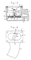
- the inlet manifolds shown in Figures 1 to 4 are of customary shape and construction and comprise an inlet part 1 and a number of side branches 2, each leading to a cylinder.
- the inlet part 1 has an admission opening 3 for the fuel mixture.
- a carburettor (not shown) is intended to be fastened, while a packing 4 disposed on the edge 3 is clampe d between the edge 3 and the carburettor.
- the manifold wall has circulation passages 5 for cooling water, which during operation is heated to a constant temperature, for example 95°C.
- a heating device 6 is placed, via the opening 3, on the bottom of the inlet part 1.
- This part comprises a dish-shaped heat sink having a thickened or flanged edge 8, which with the interposition of a member 9, which provides insulation in respect of both heat and electric current, rests on the bottom.
- a number of thermistor pellets 10 composed of material having a positive temperature coefficient (PTC) are fastened on the bottom face of the heat sink by means of an adhesive conducting heat and electricity.
- PTC positive temperature coefficient
- the heat sink has a central stump 12, over which a hollow ceramic pin 13 is pushed.
- a clamp member is disposed on the top edge of the pin 13, this member consisting, in the embodiment illustrated in Figures 1 and 2, of a spring strip 14 whose ends are inserted into openings in the packing 4.
- the strip 14 presses the heating device clampingly against the bottom of the inlet part.
- An electricity supply wire 15 connected to the heat sink extends through the hollow pin.
- a strip 17 is mounted rotatably on the ceramic pin, while bosses 18 are provided on the inside wall of the manifold 2 in in mutually opposite positions.
- various other mechanisms may be used for holding in place the heating device, which is placed on the bottom of the manifold by way of the normal inlet opening for the fuel mixture.
- electrically insulated spring snap means could be installed in the manifold to secure the heat sink.
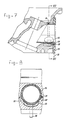
- the manifold shown in Figures 5 and 6 is intended for a twin carburettor.
- One of the inlets is provided with a heating device consisting of a heat sink 21 in the form of a hexagonal sleeve and a number of thermistor pellets 22 secured by adhesive on a number of flat faces of the sleeve.
- the heating device is secured by two springs 23 in the respective inlet of the manifold. Current can be supplied via the lip 24.
- the pellets 22 are electrically connected to frame (manifold) by springs 23.
- a thermally and electrically insulating ring 25 is disposed between the sleeve 21 and the walls of the manifold.
- Figures 7 and 8 show a head of one of the cylinders of an internal combustion engine, wherein a heating device is installed in the inlet to the cylinder, this device consisting of a heat sink 31 in the form of a sleeve having two flat faces on which thermistor pellets 32 are fastened by adhesive.
- This sleeve 31 is clamped fast by means of a spring 33, while a round strip 34 of insulating material maintains the desired spacing between the heat sink and the cylinder head.
- a flange 35 is fastened in the cylinder inlet.
- a metal lip 36 passing through the flange supplies current to the heat sink 31 via the spring 33.
- the pellets 32 are electrically connected to the cylinder head, which serves as frame, by way of the s pring 33.
- the water circulation system is not modified, that is to say in the embodiments shown in Figures 1 to 4 there is also water circulation directly under the heating device.
- the wate is at a temperature of about 95°C, and this relatively hot water ensures that after the current supply has been switched off to the thermistor pellets no "cold spot" will be formed at the site of the heat sink through the evaporating fuel and the consequent removal of heat from the environment.
- Another important advantage is that, viewed over the thickness of the thermistor material, the situation of the highest temperature is approximately in the middle, so that the loaded side, that is to say the side face of the pellets which adjoins the heat sink, has a higher temperature than is the case, under the same conditions, with known through passages provided with heating devices. The fuel mixture can then also extract more heat from the thermistor pellets.
Landscapes
- Engineering & Computer Science (AREA)
- Chemical & Material Sciences (AREA)
- Combustion & Propulsion (AREA)
- Mechanical Engineering (AREA)
- General Engineering & Computer Science (AREA)
- Resistance Heating (AREA)
- Means For Warming Up And Starting Carburetors (AREA)
- Combustion Methods Of Internal-Combustion Engines (AREA)
- Air-Conditioning For Vehicles (AREA)
Priority Applications (1)
| Application Number | Priority Date | Filing Date | Title |
|---|---|---|---|
| AT87202104T ATE57568T1 (de) | 1986-11-03 | 1987-11-02 | Brennkraftmaschine mit einer heizeinrichtung fuer das brennstoff/luft-gemisch. |
Applications Claiming Priority (2)
| Application Number | Priority Date | Filing Date | Title |
|---|---|---|---|
| NL8602782A NL8602782A (nl) | 1986-11-03 | 1986-11-03 | Verbrandingsmotor. |
| NL8602782 | 1986-11-03 |
Publications (2)
| Publication Number | Publication Date |
|---|---|
| EP0267645A1 true EP0267645A1 (fr) | 1988-05-18 |
| EP0267645B1 EP0267645B1 (fr) | 1990-10-17 |
Family
ID=19848776
Family Applications (1)
| Application Number | Title | Priority Date | Filing Date |
|---|---|---|---|
| EP87202104A Expired - Lifetime EP0267645B1 (fr) | 1986-11-03 | 1987-11-02 | Moteur à combustion interne avec moyens de chauffage pour le mélange carburant/air |
Country Status (5)
| Country | Link |
|---|---|
| US (1) | US4834053A (fr) |
| EP (1) | EP0267645B1 (fr) |
| AT (1) | ATE57568T1 (fr) |
| DE (1) | DE3765622D1 (fr) |
| NL (1) | NL8602782A (fr) |
Cited By (8)
| Publication number | Priority date | Publication date | Assignee | Title |
|---|---|---|---|---|
| US4898668A (en) * | 1988-09-30 | 1990-02-06 | Stanadyne Automotive Corp. | Fuel filter with heater |
| EP0404477A1 (fr) * | 1989-06-20 | 1990-12-27 | Texas Instruments Incorporated | Dispositif d'alimentation et dispositif de réchauffage du carburant |
| EP0456535A1 (fr) * | 1990-05-10 | 1991-11-13 | Automobiles Peugeot | Dispositif d'admission pour un moteur à combustion interne à gaz prémélangé |
| EP0472416A1 (fr) * | 1990-08-22 | 1992-02-26 | Texas Instruments Incorporated | Moteur à combustion interne avec réchauffeurs de carburant |
| EP0509982A3 (en) * | 1991-04-18 | 1993-04-14 | Avl Gesellschaft Fuer Verbrennungskraftmaschinen Und Messtechnik Mbh.Prof.Dr.Dr.H.C. Hans List | Cold start system |
| EP0469261B1 (fr) * | 1990-07-28 | 1994-07-27 | Mercedes-Benz Ag | Dispositif d'aspiration pour un moteur à combustion interne à compression de mélange |
| RU2133869C1 (ru) * | 1997-10-27 | 1999-07-27 | Акционерное общество "АвтоВАЗ" | Электронагревательное устройство |
| RU2180707C2 (ru) * | 2000-03-07 | 2002-03-20 | Драгомиров Сергей Григорьевич | Подогреватель топливовоздушной смеси для автомобильного двигателя |
Families Citing this family (10)
| Publication number | Priority date | Publication date | Assignee | Title |
|---|---|---|---|---|
| DE3805927A1 (de) * | 1988-02-25 | 1989-08-31 | Bosch Gmbh Robert | Vorrichtung zur verbesserung der gemischverteilung |
| NL8801334A (nl) * | 1988-05-24 | 1989-12-18 | Texas Instruments Holland | Verbrandingsmotor van het inspuittype, en plaat bestemd om te worden aangebracht tussen de inlaatpoorten van een cilinderblok van een dergelijke motor en een inspuitstuk. |
| US5134986A (en) * | 1990-08-22 | 1992-08-04 | Texas Instruments Incorporated | Internal combustion engine with fuel heater |
| US5048500A (en) * | 1990-08-22 | 1991-09-17 | Texas Instruments Incorporated | Internal combustion engine with fuel injectors and heaters |
| US5115787A (en) * | 1991-09-24 | 1992-05-26 | Texas Instruments Incorporated | Spark ignition combustion engine of the fuel injection type and heating element therefor |
| JPH0650220A (ja) * | 1992-07-28 | 1994-02-22 | Texas Instr Japan Ltd | 加熱装置および内燃機関用加熱システム |
| NL9401209A (nl) * | 1994-07-22 | 1996-03-01 | Texas Instruments Holland | Brandstofverhitter voor het verhitten van onder druk staande vloeibare brandstof voor een injectiemotor. |
| US5540198A (en) * | 1995-01-10 | 1996-07-30 | Hurner; Erwin | Apparatus and process for heating fuel |
| RU2152532C1 (ru) * | 1998-09-25 | 2000-07-10 | Товарищество с ограниченной ответственностью Маркетинговая фирма "СЭТМА" | Устройство для подогрева дизельного топлива |
| RU2153596C1 (ru) * | 1998-11-19 | 2000-07-27 | Концерн КЭМЗ | Устройство для нагрева диэлектрических жидкостей |
Citations (6)
| Publication number | Priority date | Publication date | Assignee | Title |
|---|---|---|---|---|
| DE2654181A1 (de) * | 1976-11-30 | 1978-06-08 | Deutsche Vergaser Gmbh Co Kg | Bewegliche elektrische heizvorrichtung in einem ansaugkanal einer brennkraftmaschine |
| DE3030812A1 (de) * | 1979-08-17 | 1981-02-26 | Nippon Soken | Brennstoffverdampfer |
| US4325344A (en) * | 1979-06-05 | 1982-04-20 | Nippon Soken, Inc. | Fuel evaporator |
| DE3300789A1 (de) * | 1983-01-12 | 1984-07-12 | Volkswagenwerk Ag, 3180 Wolfsburg | Gemischheizvorrichtung |
| US4489232A (en) * | 1980-10-13 | 1984-12-18 | Ngk Insulators, Ltd. | Apparatus for heating a mixed gas on an internal combustion engine |
| EP0157952A1 (fr) * | 1984-04-10 | 1985-10-16 | Texas Instruments Holland B.V. | Préchauffeur de mélange air-carburant |
Family Cites Families (5)
| Publication number | Priority date | Publication date | Assignee | Title |
|---|---|---|---|---|
| JPS5918134Y2 (ja) * | 1979-10-30 | 1984-05-25 | トヨタ自動車株式会社 | 内燃機関の吸気加熱装置 |
| US4387291A (en) * | 1980-11-28 | 1983-06-07 | Texas Instruments Incorporated | Fuel heater system and self-regulating heater therefor |
| US4419564A (en) * | 1981-03-30 | 1983-12-06 | Texas Instruments Incorporated | Self-regulating electric heater for use in an early fuel evaporation system |
| US4717808A (en) * | 1986-04-28 | 1988-01-05 | Gte Products | Carburetor deicer |
| NL8601460A (nl) * | 1986-06-05 | 1988-01-04 | Texas Instruments Holland | Inlaatspruitstuk van een verbrandingsmotor en voor dat spruitstuk bedoelde verwarmingsinrichting. |
-
1986
- 1986-11-03 NL NL8602782A patent/NL8602782A/nl not_active Application Discontinuation
-
1987
- 1987-11-02 US US07/115,670 patent/US4834053A/en not_active Expired - Fee Related
- 1987-11-02 AT AT87202104T patent/ATE57568T1/de not_active IP Right Cessation
- 1987-11-02 EP EP87202104A patent/EP0267645B1/fr not_active Expired - Lifetime
- 1987-11-02 DE DE8787202104T patent/DE3765622D1/de not_active Expired - Fee Related
Patent Citations (6)
| Publication number | Priority date | Publication date | Assignee | Title |
|---|---|---|---|---|
| DE2654181A1 (de) * | 1976-11-30 | 1978-06-08 | Deutsche Vergaser Gmbh Co Kg | Bewegliche elektrische heizvorrichtung in einem ansaugkanal einer brennkraftmaschine |
| US4325344A (en) * | 1979-06-05 | 1982-04-20 | Nippon Soken, Inc. | Fuel evaporator |
| DE3030812A1 (de) * | 1979-08-17 | 1981-02-26 | Nippon Soken | Brennstoffverdampfer |
| US4489232A (en) * | 1980-10-13 | 1984-12-18 | Ngk Insulators, Ltd. | Apparatus for heating a mixed gas on an internal combustion engine |
| DE3300789A1 (de) * | 1983-01-12 | 1984-07-12 | Volkswagenwerk Ag, 3180 Wolfsburg | Gemischheizvorrichtung |
| EP0157952A1 (fr) * | 1984-04-10 | 1985-10-16 | Texas Instruments Holland B.V. | Préchauffeur de mélange air-carburant |
Cited By (9)
| Publication number | Priority date | Publication date | Assignee | Title |
|---|---|---|---|---|
| US4898668A (en) * | 1988-09-30 | 1990-02-06 | Stanadyne Automotive Corp. | Fuel filter with heater |
| EP0404477A1 (fr) * | 1989-06-20 | 1990-12-27 | Texas Instruments Incorporated | Dispositif d'alimentation et dispositif de réchauffage du carburant |
| EP0456535A1 (fr) * | 1990-05-10 | 1991-11-13 | Automobiles Peugeot | Dispositif d'admission pour un moteur à combustion interne à gaz prémélangé |
| FR2661952A1 (fr) * | 1990-05-10 | 1991-11-15 | Peugeot | Dispositif d'admission pour un moteur a combustion interne a gaz premelange. |
| EP0469261B1 (fr) * | 1990-07-28 | 1994-07-27 | Mercedes-Benz Ag | Dispositif d'aspiration pour un moteur à combustion interne à compression de mélange |
| EP0472416A1 (fr) * | 1990-08-22 | 1992-02-26 | Texas Instruments Incorporated | Moteur à combustion interne avec réchauffeurs de carburant |
| EP0509982A3 (en) * | 1991-04-18 | 1993-04-14 | Avl Gesellschaft Fuer Verbrennungskraftmaschinen Und Messtechnik Mbh.Prof.Dr.Dr.H.C. Hans List | Cold start system |
| RU2133869C1 (ru) * | 1997-10-27 | 1999-07-27 | Акционерное общество "АвтоВАЗ" | Электронагревательное устройство |
| RU2180707C2 (ru) * | 2000-03-07 | 2002-03-20 | Драгомиров Сергей Григорьевич | Подогреватель топливовоздушной смеси для автомобильного двигателя |
Also Published As
| Publication number | Publication date |
|---|---|
| EP0267645B1 (fr) | 1990-10-17 |
| DE3765622D1 (de) | 1990-11-22 |
| US4834053A (en) | 1989-05-30 |
| NL8602782A (nl) | 1988-06-01 |
| ATE57568T1 (de) | 1990-11-15 |
Similar Documents
| Publication | Publication Date | Title |
|---|---|---|
| EP0267645A1 (fr) | Moteur à combustion interne avec moyens de chauffage pour le mélange carburant/air | |
| US4967706A (en) | Internal-combustion engine of the injection type, and plate intended for fitting between the inlet ports of a cylinder block of such an engine and an inlet tube | |
| EP0061848B1 (fr) | Système de chauffage du carburant et dispositif de chauffage autoréglable | |
| US4903645A (en) | Intake manifold | |
| US4603244A (en) | Fuel filter jacket | |
| EP0969199B1 (fr) | Système d'admission pour moteur à combustion interne | |
| US4313413A (en) | Fuel vaporization promoting device for an internal combustion engine | |
| EP0472416B1 (fr) | Moteur à combustion interne avec réchauffeurs de carburant | |
| US5115787A (en) | Spark ignition combustion engine of the fuel injection type and heating element therefor | |
| EP0453927B1 (fr) | Moteur à combustion interne à injection à allumage extérieur électrique | |
| US4516556A (en) | Fuel preheater | |
| EP0248503A1 (fr) | Tubulure d'admission pour moteur à combustion interne et son dispositif de chauffage | |
| US5134986A (en) | Internal combustion engine with fuel heater | |
| RU2018021C1 (ru) | Топливный фильтр для двигателя внутреннего сгорания | |
| US20030118962A1 (en) | Fuel duct for supplying fuel to a combustion chamber | |
| JPS6224039Y2 (fr) | ||
| CN221195226U (zh) | 一种进气加热装置 | |
| JPS603333Y2 (ja) | エンジンの吸気加熱装置 | |
| RU29347U1 (ru) | Электрический подогреватель двигателя | |
| JPS60204953A (ja) | 内燃機関用インテ−クエアヒ−タ | |
| RU2001127456A (ru) | Устройство подогрева двигателя внутреннего сгорания | |
| JPS5919807Y2 (ja) | 内燃機関の吸気加熱装置 | |
| JPS62218652A (ja) | 燃料加熱装置 | |
| JPH0641080Y2 (ja) | 熱風発生機 | |
| CN108999671A (zh) | 一种内置式发动机油底壳加热器 |
Legal Events
| Date | Code | Title | Description |
|---|---|---|---|
| PUAI | Public reference made under article 153(3) epc to a published international application that has entered the european phase |
Free format text: ORIGINAL CODE: 0009012 |
|
| AK | Designated contracting states |
Kind code of ref document: A1 Designated state(s): AT BE CH DE ES FR GB GR IT LI LU NL SE |
|
| 17P | Request for examination filed |
Effective date: 19881104 |
|
| 17Q | First examination report despatched |
Effective date: 19890329 |
|
| GRAA | (expected) grant |
Free format text: ORIGINAL CODE: 0009210 |
|
| AK | Designated contracting states |
Kind code of ref document: B1 Designated state(s): AT BE CH DE ES FR GB GR IT LI LU NL SE |
|
| PG25 | Lapsed in a contracting state [announced via postgrant information from national office to epo] |
Ref country code: IT Free format text: LAPSE BECAUSE OF FAILURE TO SUBMIT A TRANSLATION OF THE DESCRIPTION OR TO PAY THE FEE WITHIN THE PRE;WARNING: LAPSES OF ITALIAN PATENTS WITH EFFECTIVE DATE BEFORE 2007 MAY HAVE OCCURRED AT ANY TIME BEFORE 2007. THE CORRECT EFFECTIVE DATE MAY BE DIFFERENT FROM THE ONE RECORDED.SCRIBED TIME-LIMIT Effective date: 19901017 Ref country code: AT Effective date: 19901017 Ref country code: SE Effective date: 19901017 Ref country code: NL Effective date: 19901017 Ref country code: GR Free format text: LAPSE BECAUSE OF FAILURE TO SUBMIT A TRANSLATION OF THE DESCRIPTION OR TO PAY THE FEE WITHIN THE PRESCRIBED TIME-LIMIT Effective date: 19901017 Ref country code: CH Effective date: 19901017 Ref country code: FR Effective date: 19901017 Ref country code: BE Effective date: 19901017 Ref country code: LI Effective date: 19901017 |
|
| REF | Corresponds to: |
Ref document number: 57568 Country of ref document: AT Date of ref document: 19901115 Kind code of ref document: T |
|
| REF | Corresponds to: |
Ref document number: 3765622 Country of ref document: DE Date of ref document: 19901122 |
|
| PG25 | Lapsed in a contracting state [announced via postgrant information from national office to epo] |
Ref country code: LU Free format text: LAPSE BECAUSE OF NON-PAYMENT OF DUE FEES Effective date: 19901130 |
|
| PG25 | Lapsed in a contracting state [announced via postgrant information from national office to epo] |
Ref country code: ES Free format text: LAPSE BECAUSE OF FAILURE TO SUBMIT A TRANSLATION OF THE DESCRIPTION OR TO PAY THE FEE WITHIN THE PRESCRIBED TIME-LIMIT Effective date: 19910128 |
|
| REG | Reference to a national code |
Ref country code: CH Ref legal event code: PL |
|
| EN | Fr: translation not filed | ||
| NLV1 | Nl: lapsed or annulled due to failure to fulfill the requirements of art. 29p and 29m of the patents act | ||
| PLBE | No opposition filed within time limit |
Free format text: ORIGINAL CODE: 0009261 |
|
| STAA | Information on the status of an ep patent application or granted ep patent |
Free format text: STATUS: NO OPPOSITION FILED WITHIN TIME LIMIT |
|
| 26N | No opposition filed | ||
| PG25 | Lapsed in a contracting state [announced via postgrant information from national office to epo] |
Ref country code: GB Effective date: 19911102 |
|
| GBPC | Gb: european patent ceased through non-payment of renewal fee | ||
| PGFP | Annual fee paid to national office [announced via postgrant information from national office to epo] |
Ref country code: DE Payment date: 19921123 Year of fee payment: 6 |
|
| PG25 | Lapsed in a contracting state [announced via postgrant information from national office to epo] |
Ref country code: DE Effective date: 19940802 |