EP0267650A2 - Appareil haut-parleur et méthode - Google Patents
Appareil haut-parleur et méthode Download PDFInfo
- Publication number
- EP0267650A2 EP0267650A2 EP87202151A EP87202151A EP0267650A2 EP 0267650 A2 EP0267650 A2 EP 0267650A2 EP 87202151 A EP87202151 A EP 87202151A EP 87202151 A EP87202151 A EP 87202151A EP 0267650 A2 EP0267650 A2 EP 0267650A2
- Authority
- EP
- European Patent Office
- Prior art keywords
- assembly
- diaphragm
- frequency
- recited
- value
- Prior art date
- Legal status (The legal status is an assumption and is not a legal conclusion. Google has not performed a legal analysis and makes no representation as to the accuracy of the status listed.)
- Withdrawn
Links
Images


Classifications
-
- H—ELECTRICITY
- H04—ELECTRIC COMMUNICATION TECHNIQUE
- H04R—LOUDSPEAKERS, MICROPHONES, GRAMOPHONE PICK-UPS OR LIKE ACOUSTIC ELECTROMECHANICAL TRANSDUCERS; ELECTRIC HEARING AIDS; PUBLIC ADDRESS SYSTEMS
- H04R1/00—Details of transducers, loudspeakers or microphones
- H04R1/20—Arrangements for obtaining desired frequency or directional characteristics
- H04R1/22—Arrangements for obtaining desired frequency or directional characteristics for obtaining desired frequency characteristic only
- H04R1/28—Transducer mountings or enclosures modified by provision of mechanical or acoustic impedances, e.g. resonator, damping means
- H04R1/2807—Enclosures comprising vibrating or resonating arrangements
- H04R1/2811—Enclosures comprising vibrating or resonating arrangements for loudspeaker transducers
-
- H—ELECTRICITY
- H04—ELECTRIC COMMUNICATION TECHNIQUE
- H04R—LOUDSPEAKERS, MICROPHONES, GRAMOPHONE PICK-UPS OR LIKE ACOUSTIC ELECTROMECHANICAL TRANSDUCERS; ELECTRIC HEARING AIDS; PUBLIC ADDRESS SYSTEMS
- H04R1/00—Details of transducers, loudspeakers or microphones
- H04R1/20—Arrangements for obtaining desired frequency or directional characteristics
- H04R1/32—Arrangements for obtaining desired frequency or directional characteristics for obtaining desired directional characteristic only
- H04R1/40—Arrangements for obtaining desired frequency or directional characteristics for obtaining desired directional characteristic only by combining a number of identical transducers
- H04R1/403—Arrangements for obtaining desired frequency or directional characteristics for obtaining desired directional characteristic only by combining a number of identical transducers loud-speakers
Definitions
- the present invention relates to an open-back baffle type loudspeaker, and more particularly to such a speaker that is particularly effective in reproducing low frequency sound.
- the baffle In a loudspeaker of the open-back baffle type (sometimes called a dipole speaker), the baffle itself is a planar plate-like member, having the speaker itself mounted in the baffle. Since the forward face and the rear face of the baffle are open, the diaphram which oscillates to create the sound not only creates forward traveling sound waves, but also 180° out-of-phase sound waves which emanate rearwardly from the diaphram.
- the baffle would shield the forwardly traveling sound waves from those which are emitted rearwardly from the diaphram.
- the planar area of the baffle must be maintained within reasonable dimensions. This results in a phenomenon called low frequency cut-off or low frequency roll-off.
- the out-of-phase sound which travels rearwardly from the speaker also travels laterally and around the edge of the baffle and forwardly to create what can be an interferring wave pattern. At the higher frequencies, this is not a significant problem, but at lower frequencies, there is created an interference pattern where the sound eminated from the rear of the speaker tends to cancel out the low frequency sound which is emitted forwardly from the front of the loudspeaker.
- the loudspeaker assembly comprises a generally planar open-backed baffle having a predetermined planar area and crosswise dimensions, and providing a speaker area located in the baffle.
- a diaphram means is moveably mounted at the speaker area.
- the diaphram means is mounted to the baffle by a resilient mounting means in a manner to locate the diaphram means at an intermediate location and permit fore and aft movement from the intermediate location while yielding the resisting such movement.
- a motor means to drive the diaphram on its fore and aft movement, the motor means comprising a magnet means to create a magnetic field and a voice coil means positioned in the magnetic field.
- the magnet means and the voice coil means are mounted so as to be moveable relative to one another.
- One of the magnet means and the voice coil means is connected to the diaphram so as to be moveable therewith, and the other of the magnet and voice coil means is connected to the baffle.
- the assembly has a predetermined baffle cut-off frequency of a first frequency value, such that the assembly is characterised to produce a roll-off effect such that amplitude of the speaker output is diminished as a function of frequency diminishing from the value of said cut-off frequency.
- the assembly has a resonant frequency of a second value lower than the first frequency value.
- the assembly has a predetermined "Q" factor of a value such to produce a "Q” effect such that the assembly is characterised in that amplitude of the speaker output is increased as a function of frequency diminishing toward the value of the resonant frequency.
- the assembly is further characterised in that the "Q" factor effect substantially offsets the roll-off effect to provide an output having an amplitude response within a predetermined amplitude range from cut-off frequency to resonant frequency.
- the voice coil means is connected to the diaphram means and the magnet means is connected to the baffle.
- the "Q" factor of the assembly is as least as great as about 2, and other forms at least as great as about 3.
- the preferred range of the "Q" factor is between 2 to 4.
- the assembly comprises a plurality of speaker units, each of which comprises a related diaphram means, a related mounting means, and a related motor means. At least a first one of the units has a "Q" factor of a lower value, and at least a second of said units as a "Q" factor of a higher value. More specifically, the second unit has a resonant frequency of a lower value, and a first unit has a resonant frequency of a higher value.
- the diaphram means has a predetermined diaphram area
- the assembly has a moving mass comprising the diaphram means and components of the assembly that move therewith.
- the assembly is characterised in that the ratio of the diaphram area, expressed in square inches, to the mass of the moving mass, express in grams, is at least 2 to 1. Desirably, this ratio is at least 4 to 1, or possibly greater.
- the resonant frequency is at least as low as about 50Hz, an in another embodiment at least as low as 25Hz.
- a loudspeaker assembly is provided as indicated above. Then the baffle cut-off, the "Q" factor and the resonant frequency are selected, so that in operating the speaker, the "Q" factor effect substantially offsets the roll-off effect to produce the desired amplitude response.
- the substance of the present invention is that the operating characteristics of certain speaker components that in and of themselves already exist in the prior art are selected and combined in such a way as to provide a loudspeaker system and method with exceptional capability of reproducing low frequency sounds. It is believed that a clearer understanding of the present invention will be obtained by first describing the physical makeup of the speaker, and then discussing the selected operational characteristics of the same and how these interact to provide the unique benefits of the present invention.
- FIGs 1 and 2 there is shown a dipole speaker system having a planar baffle 10 having upper and lower edges 12 and 14, and two side edges 16 and 18.
- Four woofers 18 are mounted to the baffle 10 in a vertical array at approximately the vertical center line of the baffle plate 10.
- a mid and high frequency speaker component 20 is also mounted to the baffle 10 adjacent to the edge 16, and this component 20 can be of prior art construction if desired.
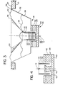
- Figure 3 is a sectional view taken substantially through the forward to rear center axis 19 of the woofer 18.
- the main components of the woofer 18 are a cone or diaphram 20 which oscillates to produce the actual sound; a yielding and resilient cone mounting structure which in this embodiment comprises an annular surround 22 and an annular spider 24; a motor 26 (made up of a fixed magnet 28 and a voice coil 30; and a mounting member 32).
- the diaphram or cone 20 has, as shown herein, the configuration of a truncated cone, having a forward circular edge 34 connected to the surround 22.
- the surround 22 is an annular member, whose inner edge is connected to the cone front edge 34, and whose outer edge 36 is connected to an outer forward flange 37 of the mounting member 32.
- the surround 22 is, in a section line taken perpendicular to a peripheral center line, of a curved or corrugated configuration, and it is made of a resilient yielding material.
- the spider 24 is an annular member which, in a section taken perpendicular to a peripheral center line of the spider 24, of a corrugated configuration.
- This spider 24 is also made of a yielding resilient material, with the outer circumferential edge 38 of the spider being connected to the mounted member 32, and the inner circular edge 40 of the spider 24 being connected to the rear edge of the cone 20.
- the surround 22 and the spider 24 collectively provide the resilient mounting for the cone 20.
- These components 22 and 24 holds the cone or diaphram 20 in an intermediate position, but will resiliently deflect both forwardly and rearwardly to permit the cone 20 to oscillate so as to produce the sound output, with the surround 22 and the spider 24 acting to restore or urge the cone 20 toward its middle position.
- the magnet 28 of the motor 26 has an outer annular portion 42 and an inner cylindrical portion 44 which are positioned relative to one another to form an annular gap 46.
- This magnet 26 can conveniently be made as two components, where the cylindrical portion 44 is formed integrally with a back plate 48 that is in turn attached to the outer annular portion 42.
- the voice coil 30 comprises a hollow cylindrical member 50 made of plastic or aluminum, and a coil 52 is wound around the cylinder 50.
- the forward edge of the cylinder 50 is connected to the rear central circular edge of the cone or diaphram 20.
- the voice coil 30 is positioned in the annular gap 46.
- the basic operation of the woofer 18 is well known in the prior art.
- the amplified audio signal is directed to the voice coil 30 so that it interacts with the field created by the magnet 28 so as to cause movement of the voice coil 30, and hence movement of the cone 20, thus producing the sound output.
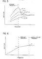
- the rise in amplitude is somewhat more complex, in that the amplitude begins to rise rather sharply at a frequency closer to the resonant frequency.
- baffle cuttoff begins at point "a" in Figure 6, where the average crosswise dimension of the baffle equals one half of the wavelength. This decline in amplitude is at a rate of about 6 decibels for each octave drop in frequency until we reacy point "b" of Figure 6, which is a resonant frequency, after which the dropoff is at a steeper curve, which is approximately an 18 decibel drop for each octave drop in frequency.
- the graphs of Figure 5 and Figure 6 are not intended to give precise values, nor are the curves intended to be precise representations of these characteristics. Rather, these are provided from free-hand sketches to illustrate the principals of the operating characterstics.
- the resonant frequency is selected to be at a location below the baffle cutoff frequency (indicated at "a" in Figure 6), and this resonant frequency is further selected to be of a value at a which (and above which) the lower frequencies are reproduced at an amplitude comparable to the amplitude through the higher range of frequencies.
- the resonant frequency will be selected to be at a value between 25-50Hz, and in the presently preferred embodiment, it is at about 25Hz, or slightly above.
- the "Q" factor is selected to be at a value much higher than that which is normally selected for opoen-back baffle speakers, and in general is between a value of 2 to 4.
- This "Q" factor is selected so that its function of increasing amplitude as the frequency becomes smaller toward the resonant value substantially counterbalances the effect of baffle roll-off, so that the amplitude remains substantially constant from the location of baffle roll-off or cut-off to the resonant frequency. Below the resonant frequency, the amplitude drops off relatively sharply.
- the total moving mass i.e., the diaphram and the components that move with it
- the area of the diaphram is made as large as possible.
- the planar frontal area of the cone 20 is included (as opposed to the actual area of the surface of the truncated cone that forms the diaphram or cone 20), and about half of the area of the surround 22 is included.
- the total moving mass was about 35 grams.
- the mass of the cone 20 can be reduced until the cone 20 begins to deflect to too great of a degree. Further investigation in the optimization of the selection and arrangement of materials indicates that the total moving mass for a 12 inch woofer having the 91 ⁇ 2 inch diameter cone may be made as low as 16 to 18 grams.
- the moving mass since it is desired to have the moving mass as small as possible, first the materials and configuration for the moving mass are selected. Then the spring constant is modified to properly match the total moving mass to give the desired resonant frequency.
- the preferred ratio of the cone or diaphram area (given in square inches) to the total moving mass (given in grams) would likely be as high as 2 to 1, and possibly as high as 4 to 1. Desirably, this ratio could be made yet higher. This, of course, can be varied further, depending upon the availability of materials of sufficient strength-to-weight ratio to get yet further optimization.
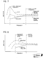
- this illustrates characteristics of a speaker assembly, where there is a roll-off curve having a cut-off frequency of 100Hz, the speaker has a resonant frequency of 25Hz, and there is a "Q" of 4.
- This "Q"-curve is such that when its effect on frequency is combined with frequency roll-off prior to any shaping or modification of the curve, there would be about a 3db drop at the 50Hz level, and this is illustrated in Figure 7.
- the "Q"-curve is "shaped" by circuitry in the crossover network to mute higher frequency values. (This will be explained below.) With this shaping, we arrive at a resultant amplitude curve which is fairly constant except for a small rise at the resonant frequency. In some instances, this may be a desirable result, depending on certain other factors.
- FIG. 9 A further example is given in Figure 9, and this illustrates how a plurality of woofers 18 can be selected with different resonant frequencies and "Q's" so as to obtain relatively constant amplitude values all the way to the lower resonant frequency.
- the cut-off frequency remains at 100Hz; the resonant frequency of two of the woofers is at 40Hz, while the resonant frequency of the other two woofers is at 25Hz. It can be seen that the resultant curve is substantially flat until we pass the lower resonant frequency level of 25Hz.
- One disadvantage of this approach is that at the very low frequencies, the effective sound output is coming more from the two woofers with the lower resonant frequencies, but in an effective way to obtain the desired output.
- crossover network refers rather broadly to all of the electrical components which not only provide for crossing over the signals, but also for a certain shaping of the signals to optimize performance. Since these are well known in the art, these will not be described in any detail herein, except to cite briefly two examples.
- Figure 10 is a simplified illustration of a circuit diagram to mute higher frequencies while passing on the lower frequency portions of the signal.
- Figure 11 is an illustration of a somewhat more sofisticated circuit to accomplish shaping. It is well within the skill of the art to select the values to obtain the proper response in the shaping of the curve.
Landscapes
- Health & Medical Sciences (AREA)
- Otolaryngology (AREA)
- Physics & Mathematics (AREA)
- Engineering & Computer Science (AREA)
- Acoustics & Sound (AREA)
- Signal Processing (AREA)
- Details Of Audible-Bandwidth Transducers (AREA)
- Obtaining Desirable Characteristics In Audible-Bandwidth Transducers (AREA)
- Diaphragms For Electromechanical Transducers (AREA)
- Audible-Bandwidth Dynamoelectric Transducers Other Than Pickups (AREA)
Applications Claiming Priority (2)
| Application Number | Priority Date | Filing Date | Title |
|---|---|---|---|
| US92885386A | 1986-11-07 | 1986-11-07 | |
| US928853 | 1986-11-07 |
Publications (2)
| Publication Number | Publication Date |
|---|---|
| EP0267650A2 true EP0267650A2 (fr) | 1988-05-18 |
| EP0267650A3 EP0267650A3 (fr) | 1990-04-25 |
Family
ID=25456885
Family Applications (1)
| Application Number | Title | Priority Date | Filing Date |
|---|---|---|---|
| EP87202151A Withdrawn EP0267650A3 (fr) | 1986-11-07 | 1987-11-05 | Appareil haut-parleur et méthode |
Country Status (2)
| Country | Link |
|---|---|
| EP (1) | EP0267650A3 (fr) |
| JP (1) | JPS63219298A (fr) |
Cited By (5)
| Publication number | Priority date | Publication date | Assignee | Title |
|---|---|---|---|---|
| WO1996014722A1 (fr) * | 1994-11-04 | 1996-05-17 | Philips Electronics N.V. | Dispositif a enceinte et haut-parleur, et haut-parleur destine a cet appareil |
| WO1999055117A1 (fr) * | 1998-04-22 | 1999-10-28 | Long Tall Ribbon Co. Ab | Transducteur electroacoustique |
| WO2000067524A3 (fr) * | 1999-04-29 | 2001-02-01 | New Transducers Ltd | Haut-parleurs |
| GB2502282A (en) * | 2012-05-21 | 2013-11-27 | Canon Kk | A small-volume loudspeaker |
| US11910153B2 (en) | 2019-05-23 | 2024-02-20 | Pss Belgium Nv | Dipole loudspeaker for producing sound at bass frequencies |
Family Cites Families (2)
| Publication number | Priority date | Publication date | Assignee | Title |
|---|---|---|---|---|
| DE1537629A1 (de) * | 1967-11-02 | 1970-01-22 | Arthur Klemt | Lautsprecherbox |
| NO129655B (fr) * | 1970-05-08 | 1974-05-06 | Neckermann Versand Kgaa |
-
1987
- 1987-11-05 EP EP87202151A patent/EP0267650A3/fr not_active Withdrawn
- 1987-11-06 JP JP28086687A patent/JPS63219298A/ja active Pending
Cited By (6)
| Publication number | Priority date | Publication date | Assignee | Title |
|---|---|---|---|---|
| WO1996014722A1 (fr) * | 1994-11-04 | 1996-05-17 | Philips Electronics N.V. | Dispositif a enceinte et haut-parleur, et haut-parleur destine a cet appareil |
| WO1999055117A1 (fr) * | 1998-04-22 | 1999-10-28 | Long Tall Ribbon Co. Ab | Transducteur electroacoustique |
| WO2000067524A3 (fr) * | 1999-04-29 | 2001-02-01 | New Transducers Ltd | Haut-parleurs |
| GB2502282A (en) * | 2012-05-21 | 2013-11-27 | Canon Kk | A small-volume loudspeaker |
| GB2502282B (en) * | 2012-05-21 | 2014-06-04 | Canon Kk | A small-volume loudspeaker |
| US11910153B2 (en) | 2019-05-23 | 2024-02-20 | Pss Belgium Nv | Dipole loudspeaker for producing sound at bass frequencies |
Also Published As
| Publication number | Publication date |
|---|---|
| EP0267650A3 (fr) | 1990-04-25 |
| JPS63219298A (ja) | 1988-09-12 |
Similar Documents
| Publication | Publication Date | Title |
|---|---|---|
| EP0400048B1 (fr) | Transducteur audio perfectionne avec membrane a souplesse modulee | |
| CA1130911A (fr) | Haut-parleur | |
| US3816672A (en) | Sound reproduction system | |
| US4619342A (en) | Multiple sound transducer system utilizing an acoustic filter to reduce distortion | |
| GB2054323A (en) | Coaxial loudspeaker system | |
| EP0072206B1 (fr) | Système haut-parleur pour produire du son cohérent | |
| CA1083972A (fr) | Enceinte acoustique a plusieurs haut-parleurs | |
| US3944757A (en) | High-fidelity moving-coil loudspeaker | |
| US4020299A (en) | Electro-acoustic transducer diaphragms | |
| US5714722A (en) | Loudspeaker | |
| US5073948A (en) | Midrange loudspeaker driver | |
| US4115667A (en) | Loudspeaker voice coil bearing | |
| US4225757A (en) | Broad band dynamic loudspeaker | |
| US4225756A (en) | Broad band dynamic loudspeaker | |
| EP0267650A2 (fr) | Appareil haut-parleur et méthode | |
| US3403235A (en) | Wide-range loudspeaker | |
| US4188711A (en) | Method of making broad band dynamic loudspeaker | |
| CA1204498A (fr) | Enceinte acoustique a plusieurs haut-parleurs | |
| US4086450A (en) | Variable thickness cone for a dynamic speaker and quality control inspection method therefor | |
| US3026958A (en) | Acoustical diaphragm | |
| WO1991007742A1 (fr) | Transducteur audio ameliore a diaphragme a flexibilite regulee | |
| JPS5830372Y2 (ja) | パツシブラジエ−タ | |
| JP3858422B2 (ja) | パネル型スピーカ装置 | |
| JP3365123B2 (ja) | ダブルコーンスピーカ | |
| GB1589998A (en) | Multiple driver loudspeaker system |
Legal Events
| Date | Code | Title | Description |
|---|---|---|---|
| PUAI | Public reference made under article 153(3) epc to a published international application that has entered the european phase |
Free format text: ORIGINAL CODE: 0009012 |
|
| AK | Designated contracting states |
Kind code of ref document: A2 Designated state(s): AT BE CH DE ES FR GB GR IT LI LU NL SE |
|
| PUAL | Search report despatched |
Free format text: ORIGINAL CODE: 0009013 |
|
| AK | Designated contracting states |
Kind code of ref document: A3 Designated state(s): AT BE CH DE ES FR GB GR IT LI LU NL SE |
|
| STAA | Information on the status of an ep patent application or granted ep patent |
Free format text: STATUS: THE APPLICATION IS DEEMED TO BE WITHDRAWN |
|
| 18D | Application deemed to be withdrawn |
Effective date: 19901026 |
|
| RIN1 | Information on inventor provided before grant (corrected) |
Inventor name: CROFT, JAMES J. Inventor name: CARVER, ROBERT W. |