EP0267666A2 - Système d'emboîtement d'une pompe - Google Patents
Système d'emboîtement d'une pompe Download PDFInfo
- Publication number
- EP0267666A2 EP0267666A2 EP87305014A EP87305014A EP0267666A2 EP 0267666 A2 EP0267666 A2 EP 0267666A2 EP 87305014 A EP87305014 A EP 87305014A EP 87305014 A EP87305014 A EP 87305014A EP 0267666 A2 EP0267666 A2 EP 0267666A2
- Authority
- EP
- European Patent Office
- Prior art keywords
- pump assembly
- receiver
- assembly
- pump
- handle
- Prior art date
- Legal status (The legal status is an assumption and is not a legal conclusion. Google has not performed a legal analysis and makes no representation as to the accuracy of the status listed.)
- Granted
Links
Images


Classifications
-
- F—MECHANICAL ENGINEERING; LIGHTING; HEATING; WEAPONS; BLASTING
- F02—COMBUSTION ENGINES; HOT-GAS OR COMBUSTION-PRODUCT ENGINE PLANTS
- F02M—SUPPLYING COMBUSTION ENGINES IN GENERAL WITH COMBUSTIBLE MIXTURES OR CONSTITUENTS THEREOF
- F02M37/00—Apparatus or systems for feeding liquid fuel from storage containers to carburettors or fuel-injection apparatus; Arrangements for purifying liquid fuel specially adapted for, or arranged on, internal-combustion engines
- F02M37/04—Feeding by means of driven pumps
- F02M37/08—Feeding by means of driven pumps electrically driven
- F02M37/10—Feeding by means of driven pumps electrically driven submerged in fuel, e.g. in reservoir
- F02M37/103—Mounting pumps on fuel tanks
-
- Y—GENERAL TAGGING OF NEW TECHNOLOGICAL DEVELOPMENTS; GENERAL TAGGING OF CROSS-SECTIONAL TECHNOLOGIES SPANNING OVER SEVERAL SECTIONS OF THE IPC; TECHNICAL SUBJECTS COVERED BY FORMER USPC CROSS-REFERENCE ART COLLECTIONS [XRACs] AND DIGESTS
- Y10—TECHNICAL SUBJECTS COVERED BY FORMER USPC
- Y10T—TECHNICAL SUBJECTS COVERED BY FORMER US CLASSIFICATION
- Y10T137/00—Fluid handling
- Y10T137/8593—Systems
- Y10T137/86348—Tank with internally extending flow guide, pipe or conduit
Definitions
- the present invention relates generally, as indicated, to a pump assembly of the plug-in type, and more particularly, to certain improvements in such a pump assembly which greatly facilitate the installation, retention and service removal of such pump assembly from a receiver within a tank such as an aircraft fuel tank from which fuel or other fluid is to be pumped by such pump assembly.
- the pump assembly includes a rotatable handle with cams thereon which cooperate with receiver lugs on the receiver housing to releasably retain the pump assembly within the receiver.
- the pump assembly is initially inserted axially part way into the receiver to a first intermediate non-operating position and then rotated a part turn to cause the cams to be received inside the receiver lugs which retain the pump assembly in a second intermediate non-operating position for pump draining. Thereafter, upon rotation of the handle to a handle locked position, the cams in cooperation with the receiver lugs will push the pump assembly axially into the receiver to an operating position.
- the cams upon rotation of the handle from the locked position to an unlocked position, the cams will pull the pump assembly axially part way out of the receiver to the second intermediate non-operating pump drain position.
- the pump assembly is movable axially into and out of sealing engagement with the receiver during rotation of the handle between the handle locked and unlocked positions.
- valves when the pump handle is in the locked position, one or more valves are opened, whereas when the pump handle is in the unlocked position, such valves are closed.
- the pump assembly cannot fall out or be pulled out of the receiver.
- the majority of the seals are desirably engaged during pump installation and disengaged during pump removal only when the highly leveraged force from the pump handle cams is active to respectively push and pull the pump assembly into and out of the receiver.
- the cams on the pump handle move to an over-center position when the handle is in the locked position, whereby any forces tending to push the pump assembly out of the receiver during operation of the pump will urge the handle toward the locked position.
- the final travel of the pump assembly in the receiver to the operating position contacts a main shut-off valve in the receiver to deflect the main shut-off valve to the open position.
- the main shut-off valve is carried by a valve spring arm which is deflected during the final travel of the pump assembly to the operating position to ensure that the main shut-off valve is securely loaded in the open position when the pump assembly is in the operating position.
- the deflection of the valve spring arm produces a reaction force which is transmitted through the pump assembly to the cams on the pump handle and into the receiver lugs to compensate for any tolerances in the receiver and pump assembly when the pump assembly is in the operating position.
- the pump housing when the pump handle is in the unlocked position with the cams received within the receiver lugs, the pump housing may, if desired, be drained of any trapped fluids by removing a drain plug from the axial outer end of the pump housing.
- the pump handle may be retained in the locked position by a removable plug-in electrical connector.
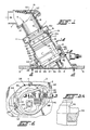
- the particular pump assembly disclosed herein is an electric motor driven fuel boost pump of the type used to pump aircraft fuel from the fuel tank 3 of the aircraft to the aircraft engines.
- the receiver 2 is permanently mounted within the fuel tank and is accessible from outside the tank through an access opening 4, for example, in the aircraft wing 5.
- the receiver is desirably inclined at an angle relative to the vertical within the fuel tank 3 as shown, whereby when the pump assembly is properly installed within the receiver, the pump assembly will also be disposed at an angle relative to the vertical to improve pump inlet fuel flow conditions and minimize pump height.
- the pump assembly 1 draws fuel into a pump inlet 6 at the upper (inner) end thereof through an inlet line 7 connected to the receiver housing 8 and discharges same under pressure through a pump outlet 10 into a pump discharge volute 11 in the receiver surrounding the pump outlet.
- the pump discharge volute 11 is in turn suitably connected to the aircraft plumbing (not shown) for directing the fuel to the aircraft engines.
- the pump assembly 1 is of an improved plug-in design which provides for the simple installation and retention of the pump assembly in the receiver as well as the easy removal therefrom by hand without the need for any tools or the like.
- a service or main inlet shut-off valve 15 at the axial inner end of the receiver is held open by engagement by a shroud 16 which surrounds the inlet 6 to the pump.
- an external shoulder 17 on the pump housing or cartridge 18 maintains a small vapor vent service valve 19 in the receiver 2 in the open position shown in Fig. 1 for venting fuel vapors from within the pump assembly 1 through radial vent passages 20 in the pump housing.
- Suitable seals 21-24 are provided between the external stepped surface of the pump housing 18 and internal stepped bore 25 in the receiver 2 on opposite sides of the pump outlet 10 and radial vent passages 20 to isolate same.
- the pump assembly is initially inserted only part way into the receiver to an intermediate non-operating position in which the shroud 16 at the inlet end of the pump housing 18 and external shoulder 17 on the pump housing have not yet engaged the respective main inlet shut-off valve 15 and vapor vent service valve 19, whereby such valves still remain closed as shown in Fig. 4. Also, all but one of the seals 21-24 are disengaged when the pump assembly is in the intermediate non-operating position shown in Fig. 4 (the seal 23 being the only one engaged) for a purpose to be subsequently described.
- the pump assembly can only be inserted into the receiver in one rotational orientation because of orientation lugs 30 on the exterior of the pump housing 18 that are received in orientation slots 32 in the receiver housing 8.
- orientation lugs 30 and associated receiver slots 32 are provided on opposite sides of the assembly.
- a rotatable handle assembly 35 is provided on the outer end of the pump housing 18 to facilitate insertion and removal of the pump assembly from the receiver.
- the handle assembly includes an outer handle portion 36 having arms 37, 38 at opposite ends thereof, with integral cams 39, 40 on the inner ends of the arms which must also be oriented out of axial alignment with receiver lugs 41, 42 on opposite sides of the receiver in order to initially insert the pump assembly into the receiver.
- the arms 37, 38 are suitably pivotally connected to opposite sides of the pump assembly to permit rotation of the handle assembly and integral cams between an unlocked position in which the handle extends downwardly from the pump assembly as shown in Figs. 4-6 and a locked position in which the handle lies up against the bottom end of the pump assembly as shown in Figs. 1 and 2.
- the handle assembly 35 Prior to insertion of the pump assembly into the receiver, the handle assembly 35 should be in the down, unlocked position to facilitate grasping of the handle portion 36 by the operator and insertion of the pump assembly into the receiver to the intermediate non-operating position previously described. Stop shoulders or ledges 43 extending part way into the respective slots 32 intermediate the length thereof act as stops limiting the initial inward movement of the pump assembly into the receiver upon engagement of the pump orientation lugs 30 with the shoulders to properly locate the handle cams 39, 40 in the same transverse plane in radial alignment with cam receiving slots 45, 46 in the respective receiver lugs 41, 42. Then, with the handle still in the down, unlocked position, the pump assembly is free to be rotated counterclockwise a part turn from the first intermediate position shown in Fig.
- the cams 39, 40 on the handle assembly 35 are received within the slots 45, 46 in the receiver lugs 41, 42 on opposite sides of the receiver so that the pump assembly cannot fall out or be pulled out of the receiver while in this position.
- the configuration of the cams 39, 40 on the handle assembly and slots 45, 46 in the receiver lugs 41, 42 are preferably such that as long as the handle assembly is in the down, unlocked position, the pump assembly is free to be rotated between such first and second intermediate positions with all but one of the seals 21-24 on the outside of the pump assembly disengaged from the receiver housing 8 and pump shroud 16 to minimize the force necessary to turn the pump assembly in the receiver.
- the second intermediate position of the pump assembly shown in Figs. 6 and 7 with the handle down in the unlocked position is the pump drain position in which the pump housing 18 can be drained of any trapped fuel or other fluid by removing a drain plug 47 from the outer end of the pump housing while the pump assembly is still fully supported within the receiver by engagement of the cams 39, 40 in the receiver lugs 41, 42 and the valves 15, 19 are closed. Also, when the pump assembly is in the second intermediate position, the orientation lugs 30 on the pump housing 18 clear the stop shoulders 43 within the receiver slots 32 so that the pump assembly is free to be moved further into the receiver to the operating position shown in Fig. 1 as described hereafter.
- Movement of the pump assembly from the pump drain position shown in Figs. 6 and 7 to the operating position shown in Figs. 1 and 2 is accomplished by pivoting the handle assembly 35 from the down, unlocked position (Figs. 6-8) to the up, locked position (Figs. 1, 2 and 12).
- the handle assembly is pivoted through the intermediate positions shown in Figs. 9-11, the pump assembly is pushed up into the receiver by the mechanical leverage of the cams 39, 40 acting against the inwardly facing surfaces 48 of the receiver lugs 41, 42.
- the leveraged force from the handle assembly and cams is used to force the other seals 22 and 24 on the outside of the pump housing 18 into engagement with the stepped receiver bore 25 and the seal 21 within the receiver bore 25 into sealing engagement with the pump shroud 16.
- the pump shroud 16 at the inner end of the pump assembly moves the service shut-off valve 15 to the open position, and an inclined ramp 50 on the pump housing engages a cone-shaped pin 51 in the center of the vapor vent service valve 19 pushing the pin back to open the valve 19.
- the service shut-off valve 15 is desirably biased into engagement with the open inner end 28 of the receiver 2 by a spring arm 52 supported by an inlet valve pump housing casting 53.
- the service shut-off valve 15 desirably bottoms on the top of the inlet valve housing casting so that the final travel of the pump assembly into the receiver deflects the valve spring arm 52 slightly to ensure that the service shut-off valve is loaded securely in the open position.
- valve spring arm 52 Such loading of the valve spring arm 52 creates a reaction force which is transmitted through the pump housing 18 to the cams 39, 40 on the pump handle assembly 35 and into the receiver lugs 41, 42, which is sufficient to compensate for any tolerances in the receiver and pump assembly when the pump assembly is in the operating position shown in Figs. 1 and 2.
- the pump assembly cannot be inserted past the operating position because of the stepped configuration of the receiver and pump housing which limits axial inward movement of the pump assembly within the receiver housing.
- the pump handle cams 39, 40 are desirably in an over-center position (see Fig. 12), whereby any forces acting on the pump assembly tending to push the pump assembly out of the receiver will urge the handle assembly tighter up against the bottom of the pump assembly to retain the pump assembly in the operating position.
- an electrical connector 55 is connected to the outer end of the pump assembly to provide power to operate the same, following which a wing access cover plate 56 is inserted in place to close the access opening 4 in the wing 5 (see Fig. 1).
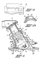
- the shape of the electrical connector 55 and handle assembly 35 are such that the handle assembly will interfere with the attachment of the electrical connector to the pump assembly except when the handle assembly is in the closed, locked position.
- the handle assembly and electrical connector will interfere with the attachment of the wing access cover plate 56 to the wing if the pump handle is not in the full locked position and the electrical connector is not attached to the pump assembly.
- the electrical connector desirably traps the handle in the locked position by overlapping a handle locking tab 58 on the handle assembly as shown in Figs. 2, 3 and 3A.
- the installation procedure is reversed. That is, first the wing access cover plate 56 is removed, followed by removal of the electrical connector 55. Then the pump handle 35 is pivoted downwardly from the locked position to the unlocked position, during which the mechanical advantage of the cams 39, 40 is made use of once again, this time to pull the pump assembly part way out of the receiver housing until the service shut-off valve 15 and vapor vent service valve 19 close and all but one of the seals 22-24 on the outside of the pump assembly become disengaged within the receiver bore due to the stepped configuration of the receiver bore and pump housing and the seal 21 becomes disengaged from the pump shroud 16.
- the pump assembly of the present invention provides a simple and effective way, through mechanical leverage, both to push the pump assembly into the receiver and pull the pump assembly out depending on the direction of handle rotation.
- the cams on the handle assembly retain the pump assembly within the receiver housing in the locked position which corresponds to the operating position of the pump assembly, and prevent the pump assembly from falling out or being pulled out of the receiver when the handle assembly is in the unlocked position and the pump assembly is in the pump drain position.
- the pump axis is desirably inclined from the vertical to improve pump inlet fuel flow conditions and minimize pump height.
Landscapes
- Engineering & Computer Science (AREA)
- Chemical & Material Sciences (AREA)
- Combustion & Propulsion (AREA)
- Mechanical Engineering (AREA)
- General Engineering & Computer Science (AREA)
- Details Of Reciprocating Pumps (AREA)
- Structures Of Non-Positive Displacement Pumps (AREA)
Applications Claiming Priority (2)
| Application Number | Priority Date | Filing Date | Title |
|---|---|---|---|
| US06/929,770 US4734016A (en) | 1986-11-13 | 1986-11-13 | Plug-in type pump assembly |
| US929770 | 1992-08-12 |
Publications (3)
| Publication Number | Publication Date |
|---|---|
| EP0267666A2 true EP0267666A2 (fr) | 1988-05-18 |
| EP0267666A3 EP0267666A3 (en) | 1989-08-02 |
| EP0267666B1 EP0267666B1 (fr) | 1991-10-16 |
Family
ID=25458425
Family Applications (1)
| Application Number | Title | Priority Date | Filing Date |
|---|---|---|---|
| EP19870305014 Expired - Lifetime EP0267666B1 (fr) | 1986-11-13 | 1987-06-05 | Système d'emboîtement d'une pompe |
Country Status (5)
| Country | Link |
|---|---|
| US (1) | US4734016A (fr) |
| EP (1) | EP0267666B1 (fr) |
| JP (1) | JP2747291B2 (fr) |
| DE (1) | DE3773843D1 (fr) |
| ES (1) | ES2025658T3 (fr) |
Cited By (3)
| Publication number | Priority date | Publication date | Assignee | Title |
|---|---|---|---|---|
| DE102004017278A1 (de) * | 2004-04-07 | 2005-11-03 | J. Eberspächer GmbH & Co. KG | Pumpenhalterung |
| US9352646B2 (en) | 2010-05-06 | 2016-05-31 | YFS Automotive Systems, Inc | Vehicle fuel tank |
| US9994101B2 (en) | 2010-05-06 | 2018-06-12 | Jeff Yager | Vehicle fuel tank |
Families Citing this family (11)
| Publication number | Priority date | Publication date | Assignee | Title |
|---|---|---|---|---|
| EP0372507B2 (fr) * | 1988-12-07 | 1996-04-03 | Nissan Motor Co., Ltd. | Aménagement de la pompe à carburant et d'un réservoir secondaire dans un réservoir à carburant pour automobile |
| US5538406A (en) * | 1994-03-02 | 1996-07-23 | Johnson Pumps Of America, Inc. | Removable cartridge-type pump for live well bait tanks in sport fishing boats |
| US6045340A (en) * | 1997-10-10 | 2000-04-04 | Rule Industries, Inc. | Locking mechanism for a removable live well pump |
| US6276908B1 (en) | 1997-10-10 | 2001-08-21 | Rule Industries, Inc. | Latching mechanism for use with pumps used in marine environments |
| JP4119525B2 (ja) * | 1998-05-21 | 2008-07-16 | 日本電産コパル株式会社 | ヒートシンク付きファンモータ |
| US6874756B2 (en) | 2001-04-26 | 2005-04-05 | Swagelok Company | Snap assembly actuator housing and valve mounting bracket |
| USD486501S1 (en) | 2001-10-13 | 2004-02-10 | Swagelok Company | Combined snap assembly actuator housing and mounting bracket |
| USD500842S1 (en) | 2002-05-31 | 2005-01-11 | Swagelok Company | Manual valve actuator with cam |
| USD505681S1 (en) | 2003-08-01 | 2005-05-31 | Attwood Corporation | Pump |
| FR2962405B1 (fr) | 2010-07-06 | 2013-06-07 | Airbus Operations Sas | Aeronef comprenant une pompe de carburant fixee a un panneau de reservoir |
| GB2624252A (en) * | 2022-11-14 | 2024-05-15 | Airbus Operations Ltd | Aircraft access cover |
Family Cites Families (12)
| Publication number | Priority date | Publication date | Assignee | Title |
|---|---|---|---|---|
| GB577164A (en) * | 1944-09-14 | 1946-05-07 | Pulsometer Eng Co | Improvements in or relating to centrifugal pumps |
| US3143971A (en) * | 1957-12-23 | 1964-08-11 | Borg Warner | Plug-in type immersible pump |
| US2940643A (en) * | 1958-06-06 | 1960-06-14 | Lockheed Aircraft Corp | Handling tool |
| US3000543A (en) * | 1958-09-22 | 1961-09-19 | Borg Warner | Plug-in pump assembly |
| US2978150A (en) * | 1958-10-24 | 1961-04-04 | Borg Warner | Plug-in pump assembly |
| US3172365A (en) * | 1963-02-05 | 1965-03-09 | Thompson Ramo Wooldridge Inc | Plug-in type fuel pump |
| US3679092A (en) * | 1969-09-15 | 1972-07-25 | Sullivan Products Inc | Fuel tank for use in model airplanes |
| US4324532A (en) * | 1980-01-24 | 1982-04-13 | Trw Inc. | Cartridge pump |
| US4403923A (en) * | 1981-05-12 | 1983-09-13 | Korchin Herbert P | Submersible pump |
| JPS5987264A (ja) * | 1982-11-10 | 1984-05-19 | Yanmar Diesel Engine Co Ltd | 多気筒機関の燃料噴射装置 |
| JPS61164507A (ja) * | 1985-01-16 | 1986-07-25 | 三洋電機株式会社 | 固定装置 |
| US4661046A (en) * | 1985-09-26 | 1987-04-28 | Ruyle Phillip L | Manure vacuum wagon power assist auger |
-
1986
- 1986-11-13 US US06/929,770 patent/US4734016A/en not_active Expired - Lifetime
-
1987
- 1987-06-05 DE DE8787305014T patent/DE3773843D1/de not_active Expired - Lifetime
- 1987-06-05 EP EP19870305014 patent/EP0267666B1/fr not_active Expired - Lifetime
- 1987-06-05 ES ES87305014T patent/ES2025658T3/es not_active Expired - Lifetime
- 1987-07-23 JP JP18240287A patent/JP2747291B2/ja not_active Expired - Fee Related
Cited By (3)
| Publication number | Priority date | Publication date | Assignee | Title |
|---|---|---|---|---|
| DE102004017278A1 (de) * | 2004-04-07 | 2005-11-03 | J. Eberspächer GmbH & Co. KG | Pumpenhalterung |
| US9352646B2 (en) | 2010-05-06 | 2016-05-31 | YFS Automotive Systems, Inc | Vehicle fuel tank |
| US9994101B2 (en) | 2010-05-06 | 2018-06-12 | Jeff Yager | Vehicle fuel tank |
Also Published As
| Publication number | Publication date |
|---|---|
| JPS63124879A (ja) | 1988-05-28 |
| US4734016A (en) | 1988-03-29 |
| EP0267666B1 (fr) | 1991-10-16 |
| EP0267666A3 (en) | 1989-08-02 |
| DE3773843D1 (de) | 1991-11-21 |
| ES2025658T3 (es) | 1992-04-01 |
| JP2747291B2 (ja) | 1998-05-06 |
Similar Documents
| Publication | Publication Date | Title |
|---|---|---|
| EP0267666B1 (fr) | Système d'emboîtement d'une pompe | |
| EP0660793B1 (fr) | Bouchon a fixation rapide pour reservoir de carburant | |
| USRE36959E (en) | Lockable pressure relief fuel cap | |
| US6446826B1 (en) | Seal for filler neck closure assembly | |
| US20040083779A1 (en) | Dust cover lock system for vehicle filler neck | |
| GB2193123A (en) | Centrifugal oil separator | |
| WO1991002477A1 (fr) | Verrouillage pour marmite a pression | |
| CN109715264B (zh) | 空气过滤器 | |
| GB2069605A (en) | Cartridge pump | |
| CN102369328B (zh) | 用于路政设备的窨井盖和相应的路政设备 | |
| US4411312A (en) | Water-tight conduit well cap | |
| US3539272A (en) | Canister pump assembly | |
| US20050166983A1 (en) | Flush mounted waste disposal service panel assembly | |
| US5056678A (en) | Access port sealing device | |
| AU761724B2 (en) | Safety valve, in particular for a refuelling vent line | |
| US8210382B2 (en) | Locking mechanism for home heating fuel oil fill port | |
| US4781527A (en) | Cartridge pump | |
| US5993151A (en) | Centrifugal pump device | |
| JPH0116352B2 (fr) | ||
| GB2099982A (en) | Steam trap | |
| CN113167428A (zh) | 压力密封塞子 | |
| CN116472222B (zh) | 用于飞行器的排放阀及相关方法 | |
| EP1340011B1 (fr) | Soupapes | |
| US4749542A (en) | Removable check valve for use in a nuclear reactor | |
| JPH0522879Y2 (fr) |
Legal Events
| Date | Code | Title | Description |
|---|---|---|---|
| PUAI | Public reference made under article 153(3) epc to a published international application that has entered the european phase |
Free format text: ORIGINAL CODE: 0009012 |
|
| AK | Designated contracting states |
Kind code of ref document: A2 Designated state(s): BE DE ES FR GB IT |
|
| PUAL | Search report despatched |
Free format text: ORIGINAL CODE: 0009013 |
|
| AK | Designated contracting states |
Kind code of ref document: A3 Designated state(s): BE DE ES FR GB IT |
|
| 17P | Request for examination filed |
Effective date: 19900119 |
|
| 17Q | First examination report despatched |
Effective date: 19900719 |
|
| RAP1 | Party data changed (applicant data changed or rights of an application transferred) |
Owner name: LEAR ROMEC CORP. |
|
| GRAA | (expected) grant |
Free format text: ORIGINAL CODE: 0009210 |
|
| AK | Designated contracting states |
Kind code of ref document: B1 Designated state(s): BE DE ES FR GB IT |
|
| ET | Fr: translation filed | ||
| REF | Corresponds to: |
Ref document number: 3773843 Country of ref document: DE Date of ref document: 19911121 |
|
| ITF | It: translation for a ep patent filed | ||
| REG | Reference to a national code |
Ref country code: ES Ref legal event code: FG2A Ref document number: 2025658 Country of ref document: ES Kind code of ref document: T3 |
|
| PLBE | No opposition filed within time limit |
Free format text: ORIGINAL CODE: 0009261 |
|
| STAA | Information on the status of an ep patent application or granted ep patent |
Free format text: STATUS: NO OPPOSITION FILED WITHIN TIME LIMIT |
|
| 26N | No opposition filed | ||
| PGFP | Annual fee paid to national office [announced via postgrant information from national office to epo] |
Ref country code: FR Payment date: 19960610 Year of fee payment: 10 |
|
| PGFP | Annual fee paid to national office [announced via postgrant information from national office to epo] |
Ref country code: GB Payment date: 19960618 Year of fee payment: 10 |
|
| PGFP | Annual fee paid to national office [announced via postgrant information from national office to epo] |
Ref country code: BE Payment date: 19960624 Year of fee payment: 10 |
|
| PGFP | Annual fee paid to national office [announced via postgrant information from national office to epo] |
Ref country code: DE Payment date: 19960626 Year of fee payment: 10 |
|
| PGFP | Annual fee paid to national office [announced via postgrant information from national office to epo] |
Ref country code: ES Payment date: 19960628 Year of fee payment: 10 |
|
| PG25 | Lapsed in a contracting state [announced via postgrant information from national office to epo] |
Ref country code: GB Free format text: LAPSE BECAUSE OF NON-PAYMENT OF DUE FEES Effective date: 19970605 |
|
| PG25 | Lapsed in a contracting state [announced via postgrant information from national office to epo] |
Ref country code: ES Free format text: LAPSE BECAUSE OF EXPIRATION OF PROTECTION Effective date: 19970606 |
|
| PG25 | Lapsed in a contracting state [announced via postgrant information from national office to epo] |
Ref country code: BE Effective date: 19970630 |
|
| BERE | Be: lapsed |
Owner name: LEAR ROMEC CORP. Effective date: 19970630 |
|
| GBPC | Gb: european patent ceased through non-payment of renewal fee |
Effective date: 19970605 |
|
| PG25 | Lapsed in a contracting state [announced via postgrant information from national office to epo] |
Ref country code: FR Free format text: LAPSE BECAUSE OF NON-PAYMENT OF DUE FEES Effective date: 19980227 |
|
| PG25 | Lapsed in a contracting state [announced via postgrant information from national office to epo] |
Ref country code: DE Free format text: LAPSE BECAUSE OF NON-PAYMENT OF DUE FEES Effective date: 19980303 |
|
| REG | Reference to a national code |
Ref country code: FR Ref legal event code: ST |
|
| REG | Reference to a national code |
Ref country code: FR Ref legal event code: ST |
|
| REG | Reference to a national code |
Ref country code: ES Ref legal event code: FD2A Effective date: 20000201 |
|
| PG25 | Lapsed in a contracting state [announced via postgrant information from national office to epo] |
Ref country code: IT Free format text: LAPSE BECAUSE OF NON-PAYMENT OF DUE FEES Effective date: 20050605 |