EP0267743A2 - Stickmaschine - Google Patents
Stickmaschine Download PDFInfo
- Publication number
- EP0267743A2 EP0267743A2 EP87309816A EP87309816A EP0267743A2 EP 0267743 A2 EP0267743 A2 EP 0267743A2 EP 87309816 A EP87309816 A EP 87309816A EP 87309816 A EP87309816 A EP 87309816A EP 0267743 A2 EP0267743 A2 EP 0267743A2
- Authority
- EP
- European Patent Office
- Prior art keywords
- pulse
- pulses
- timing
- counter
- driving shaft
- Prior art date
- Legal status (The legal status is an assumption and is not a legal conclusion. Google has not performed a legal analysis and makes no representation as to the accuracy of the status listed.)
- Withdrawn
Links
Images



Classifications
-
- D—TEXTILES; PAPER
- D05—SEWING; EMBROIDERING; TUFTING
- D05C—EMBROIDERING; TUFTING
- D05C3/00—General types of embroidering machines
- D05C3/04—General types of embroidering machines with horizontal needles
-
- G—PHYSICS
- G05—CONTROLLING; REGULATING
- G05B—CONTROL OR REGULATING SYSTEMS IN GENERAL; FUNCTIONAL ELEMENTS OF SUCH SYSTEMS; MONITORING OR TESTING ARRANGEMENTS FOR SUCH SYSTEMS OR ELEMENTS
- G05B19/00—Program-control systems
- G05B19/02—Program-control systems electric
- G05B19/04—Program control other than numerical control, i.e. in sequence controllers or logic controllers
- G05B19/07—Program control other than numerical control, i.e. in sequence controllers or logic controllers where the program is defined in the fixed connection of electrical elements, e.g. potentiometers, counters or transistors
-
- G—PHYSICS
- G05—CONTROLLING; REGULATING
- G05B—CONTROL OR REGULATING SYSTEMS IN GENERAL; FUNCTIONAL ELEMENTS OF SUCH SYSTEMS; MONITORING OR TESTING ARRANGEMENTS FOR SUCH SYSTEMS OR ELEMENTS
- G05B2219/00—Program-control systems
- G05B2219/20—Pc systems
- G05B2219/25—Pc structure of the system
- G05B2219/25045—Electronic cam, encoder for sequence control as function of position, programmable switch pls
Definitions
- THIS INVENTION relates to an embroidery lace machine comprising control apparatus for generating timing control signals for controlling the operation of a plurality of mechanisms each of which is brought into and out of operation by connection to and disconnection from a main driving shaft of the machine.
- Each of the mechanisms to be driven is adapted to be connected to or disconnected from the main driving shaft at a time when the rotating driving shaft reaches a predetermined angular position. This predetermined angular position or timing varies for each mechanism. It is known to obtain the required timing signals for controlling the connection and disconnection of the controlled mechanisms of the machine in two ways.
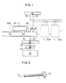
- one known way of generating the required timing signals is to provide a main driving shaft 1 of the machine with a plurality of cam dogs 2 for actuating respective detector switches 3.
- the cam dogs are provided in pairs with the two cam dogs of each pair respectively defining the points of connection and disconnection or a corresponding mechanism.
- one cam dog 2A of the pair of cam dogs 2A, 2B actuates a detector 3A associated with the connection of a needle to the driving shaft and the other cam dogs 2B actuates a detector 3B associated with the disconnection of the needle from the driving shaft.
- the pair of cam dogs 2C and 2D are associated with respective detectors 3C and 3D respectively associated with the connection of a shuttle to the driving shaft and the disconnection of the shuttle from the driving shaft.
- the arrow 4 indicates that the main driving shaft 1 is connected to the needle, shuttle and any other controlled mechanisms driven from the driving shaft by suitable drive connections.
- Timing signals for the connection and disconnection of the controlled mechanisms is to couple the main driving shaft with cylindrical signal generating rings having electrically conductive portions and electrically non-conductive portions constituting respective timing signal generators corresponding to the mechanisms to be controlled so that timing signals may be generated according to interruptions in electrical current picked up from the rings.
- An object of this invention is to eliminate or at least reduce the above-mentioned draw backs of the prior art and to provide an embroidery lace machine having timing control apparatus which can accurately generate timing control signals using relatively simple means.
- the present invention provides an embroidery lace machine in which each of a plurality of mechanisms is brought into and out of operation by connection to and disconnection from a main driving shaft of the machine at predetermined times during the rotation of the driving shaft, characterised by signal generating means for generating a reference pulse each time the driving shaft is in a reference rotational position and angular position pulses indicating the rotational displacement of the shaft from the reference position, and counting means for counting the number of angular position pulses following the reference pulse and generating a timing control signal to actuate the operation of each mechanism when the number of angular position pulses counted by the counter coincides with a respective preset count associated with that mechanism.
- the present invention enables a single rotational angle detecting means, such as a rotary encoder, to be provided on the main driving shaft instead of a respective detecting means for each mechanism.
- a single rotational angle detecting means such as a rotary encoder
- timing signals for connecting and disconnecting all the mechanisms can be derived using a single rotational angle detecting means. Therefore, alteration or modification of the timing of the operation of any one of the controlled mechanisms may be effected by simply changing the preset count associated with the mechanism in question.
- the accuracy with which the timing is detected may also be improved relative to the accuracy of the prior art constructions.
- an embroidery lace machine has a main driving shaft 1 and a plurality of mechanisms driven from the main driving shaft 1, such as a needle 5, a shuttle 6 in shuttle box 7, thread carriers 8 for a thread 9 and a borer 10.
- Each of the mechanisms is driven by connecting and disconnecting a respective drive coupling to the shaft with a predetermined timing relative to the rotation of the shaft 1.
- Control apparatus for generating suitable timing signals for connecting the various mechanisms to and disconnecting them from the driving shaft as illustrated in Figures 1 to 5.
- a single rotary encoder 15 is mounted on the main driving shaft 1 of the machine and, as the driving shaft rotates, serves to generate an intermittent reference pulse signal and a continous angular position pulse signal as the main driving shaft rotates.
- the drive shaft is coupled (as indicated by arrow 14) by suitable electrical couplings (not shown in Figure 2) for connecting the mechanisms to be driven by the shaft.
- a single reference pulse 16 is generated each time the main driving shaft passes through a reference rotational position, in this case the needle drawing position, for example.
- the continuous angular position pulse signal consists of a train of pulses 17 one of which is generated each time the main driving shaft rotates through a predetermined angle, for example one degree.
- the rotary encoder 15 has output lines 18 and 19 connected to each of a series of counter units, such as 20A, 20B and 20C, each of which corresponds to one of the mechanisms to be operated from the main driving shaft.
- These counter units are of identical construction and only the first counter unit 20A will therefore be described in detail.
- the counter unit 20A comprises a subtraction counter 21 having a first input 22 connected to a set count memory 23 for storing a count corresponding to the number of angular pulses separating the reference position of the driving shaft and the desired timing of the operation of the respective mechanism to be driven.
- the count stored in the memory 23 is set by a timing setter 24 for example by means of key input.
- the subtraction counter 21 has a second input 25 for receiving an enabling signal from a start-stop device 26 receiving an external control signal on its input 27.
- the output lines 18 and 19 of the rotary encoder 15 are connected to respective third and fourth inputs 28 and 29 of the subtraction counter 21 and serve to supply such inputs respectively with the reference pulses and the angular pulses.
- the control signal applied to the input 26 of the device 25 is derived from the operation signals for each mechanism which exist in the pattern data for an embroidery lace machine and is input to the counter unit synchronously with or in advance of the reference pulse 16 supplied by the rotary encoder 15.
- the subtraction counter 21 has an output 30 connected through a one-shot circuit 31 and an amplifier 32 to an electrical coupling device 33 for connecting and disconnecting an associated mechanism of the machine to the main driving shaft 1.
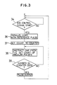
- a control signal 35 (see Figure 4) is applied to input 27 of the device 26, thereby causing subtraction counter 21 to be supplied with an enabling signal on line 25 to place the counter unit 20A in a stand by condition.
- the reference pulse signal 16 is applied to input 28 of subtraction counter 21, and the preset count in the memory 23 is transferred to the subtraction counter in a third step 37.
- the subtraction counter 21 thereafter operates in a fourth step 38 to subtract a count of one from the preset count each time an angular pulse is received from the rotary encoder at input 29.
- a fifth step 39 the number remaining in the subtraction counter 21 is determined and the subtraction continues until the number remaining in the counter reaches zero, whereupon an output timing pulse 40 (see Figure 4) is delivered on output 30 of subtraction counter 21 to the one-shot circuit 31 which serves to generate a timing control signal 41 which is supplied on output 42 to amplifier 32 which delivers an amplified timing control signal on its output 43 to actuate the coupling device 33.
- the timing control signal 41 generated by the circuit 31 is in the form of a pulse or predetermined duration with a leading edge 44 the timing of which is determined by the timing of the counter output pulse 40.
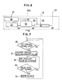
- Figure 6 illustrates a counter unit 50A of a second embodiment of the present invention, with Figure 7 showing the operational flow chart of this second embodiment.
- FIG 6 components which are the same as corresponding elements in the counter unit 20A are indicated by the same reference numerals.
- the difference between the counter units 50A and 20A is that an addition counter 51 and a comparator 52 are used in the counter unit 50A instead of the subtraction counter 21 in the counter unit 20A.
- the counter unit 51 still receives the reference pulses, angular pulses and enabling signals on inputs 18, 19 and 25 respectively but provides an input 53 of comparator 52 and accumulating count corresponding to the number of angular pulses counted since the receipt of the reference pulse.
- the comparator 52 has a second input 54 on which it receives the set count from the memory 23.
- a third input 55 of the comparator 52 receives an enabling signal from the start-stop device 26.
- An output signal of the comparator 52 is delivered on output line 56 which is, like output line 30 of subtraction counter 21 connected to the coupling mechanism 33 via one-shot circuit 31 and amplifier 32 (not shown in Figure 6).
- a first step 60 the counter unit 50A is placed in a stand-by condition by the input of a control signal to input 27 of start stop device 26.
- the counter 51 is cleared to zero upon receipt of the reference pulse at its input 28.
- each angular pulse received at input 29 after the reference pulse is added to the count in counter 51.
- the comparator compares the preset count at its input 54 with the accumulated count at its input 53 and, if these counts are the same, acts in a fifth step 64 to deliver a timing pulse like the pulse 35 ( Figure 4) on its output 56.
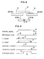
- FIG. 8 A third embodiment of the invention is illustrated by Figures 8 and 9.
- setting of the duration of operation of the mechanism to be driven is determined by the length of the timing signal delivered by the one-shot circuit 35.
- the timing of both the start and finish of the operation of the mechanism can be set independently.
- the third embodiment of the invention employs a pair of first and second counter units 20A or 50A having their outputs 30 or 56 connected to respective inputs of a flip-flop 70 having an output 71 connected to the coupling mechanism of the mechanism to be actuated by an amplifier (not shown).
- the first counter is provided with a preset count corresponding to the timing of the beginning of the operation of the mechanism and the second counter is provided with a preset count corresponding to the timing of the ending of the operation.
- the two counter units are placed in stand by condition by the application of control signal 31 to input 27 and thereafter the two units each count the angular pulses 17 received after reference pulse 16 and produce respective output pulses 72 and 73 when their counts reach the respective preset counts.
- the application of the pulses 72 and 73 to the respective inputs of the flip-flop 70 cause the flip-flop to deliver on its output 71 a timing signal 74 in the form of a pulse having the timing of its leading edge 75 determined by the pulse 72 and the timing of its trailing edge 76 determined by the pulse 73.
- a rotary encoder 15 is provided in addition to means for rotating the main driving shaft.
- the driving signals supplied to the motor may be utilised as the angular pulse signals without the need for a separate rotary encoder. In that case, however, it will be necessary to generate reference pulses separately by suitable means.
- the above described embodiments of the present invention thus enable timing signals for operating individual mechanisms from the main driving shaft of an embroidery lace machine to be accurately generated without separate timing detecting means having to be provided for each mechanism, thereby simply filing the whole system.
- the higher the frequency of the angular pulses the greater the accuracy of operation.
- the timing of the connection and disconnection of the mechanisms may, moreover, readily be adjusted and changed.
Landscapes
- Engineering & Computer Science (AREA)
- Textile Engineering (AREA)
- Physics & Mathematics (AREA)
- General Physics & Mathematics (AREA)
- Automation & Control Theory (AREA)
- Sewing Machines And Sewing (AREA)
- Automatic Embroidering For Embroidered Or Tufted Products (AREA)
Applications Claiming Priority (2)
| Application Number | Priority Date | Filing Date | Title |
|---|---|---|---|
| JP61262745A JPS63120157A (ja) | 1986-11-06 | 1986-11-06 | レ−ス刺しゆう機 |
| JP262745/86 | 1986-11-06 |
Publications (2)
| Publication Number | Publication Date |
|---|---|
| EP0267743A2 true EP0267743A2 (de) | 1988-05-18 |
| EP0267743A3 EP0267743A3 (de) | 1989-05-24 |
Family
ID=17379995
Family Applications (1)
| Application Number | Title | Priority Date | Filing Date |
|---|---|---|---|
| EP87309816A Withdrawn EP0267743A3 (de) | 1986-11-06 | 1987-11-05 | Stickmaschine |
Country Status (3)
| Country | Link |
|---|---|
| US (1) | US4913072A (de) |
| EP (1) | EP0267743A3 (de) |
| JP (1) | JPS63120157A (de) |
Cited By (1)
| Publication number | Priority date | Publication date | Assignee | Title |
|---|---|---|---|---|
| EP0602383A3 (de) * | 1992-12-18 | 1996-03-20 | Wirkbau Textilmasch Gmbh | Elektronische Steuereinheit für Maschinen, insbesondere Textilmaschinen. |
Family Cites Families (11)
| Publication number | Priority date | Publication date | Assignee | Title |
|---|---|---|---|---|
| US3218532A (en) * | 1962-12-03 | 1965-11-16 | Hughes Aircraft Co | Numerically controlled positioning system |
| US3355642A (en) * | 1964-06-26 | 1967-11-28 | Superior Electric Co | Plural channel electric pulse supplying device |
| GB1079385A (en) * | 1964-06-30 | 1967-08-16 | Ball Brothers Co Inc | Glass forming machine with automatic control system |
| DE2547439A1 (de) * | 1975-10-23 | 1977-04-28 | Merten Kg Pulsotronic | Werkzeugsicherung, insbesondere fuer eine werkzeugmaschine |
| DE2825969A1 (de) * | 1978-06-14 | 1979-12-20 | Zangs Ag Maschf | Verfahren zur bestimmung der schaltzeitpunkte fuer sonderfunktionen von automatischen stick-, stepp- und naehmaschinen |
| JPS578810A (en) * | 1980-06-18 | 1982-01-18 | Mitsubishi Electric Corp | Intermittent operation controller of equipment |
| JPS5730414A (en) * | 1980-07-30 | 1982-02-18 | Fujitsu Ltd | Offset automatic compensating system |
| CH651333A5 (de) * | 1981-02-04 | 1985-09-13 | Saurer Ag Adolph | Stelleinrichtung fuer eine mechanische schalthebelanordnung an einer stickmaschine. |
| JPS61141393A (ja) * | 1984-12-11 | 1986-06-28 | 東海工業ミシン株式会社 | ミシンの糸切れ検出装置 |
| DE3564829D1 (en) * | 1985-03-02 | 1988-10-13 | Motema Textilmaschinen Gmbh | Embroidering machine with shuttles |
| DE3700210C2 (de) * | 1986-01-09 | 1996-02-29 | Tokai Ind Sewing Machine | Mehrkopf-Stickmaschine |
-
1986
- 1986-11-06 JP JP61262745A patent/JPS63120157A/ja active Granted
-
1987
- 1987-11-05 EP EP87309816A patent/EP0267743A3/de not_active Withdrawn
- 1987-11-05 US US07/116,841 patent/US4913072A/en not_active Expired - Fee Related
Cited By (1)
| Publication number | Priority date | Publication date | Assignee | Title |
|---|---|---|---|---|
| EP0602383A3 (de) * | 1992-12-18 | 1996-03-20 | Wirkbau Textilmasch Gmbh | Elektronische Steuereinheit für Maschinen, insbesondere Textilmaschinen. |
Also Published As
| Publication number | Publication date |
|---|---|
| JPH0260781B2 (de) | 1990-12-18 |
| JPS63120157A (ja) | 1988-05-24 |
| US4913072A (en) | 1990-04-03 |
| EP0267743A3 (de) | 1989-05-24 |
Similar Documents
| Publication | Publication Date | Title |
|---|---|---|
| DE69612146T2 (de) | Verfahren zum starten eines permanent-magnet-synchronmotors mit rotierendem positionsdetektor und motorregler | |
| DE69603643T2 (de) | Positionsgeber | |
| EP0735664A2 (de) | Mit hoher Taktfrequenz arbeitendes Winkelregelungssystem für einen geschalteten Reluktanzmotorantrieb | |
| US4030720A (en) | Paper stacker | |
| JP4078065B2 (ja) | 複数のユニットで進行するプロセスを同期化する装置および方法 | |
| EP0449037B1 (de) | Positionsgeber | |
| EP0833130B1 (de) | Positionsmesssystem und Messverfahren | |
| DE29880136U1 (de) | Steuerungssystem für Fleischemulsionspumpen in eine Fleischumhüllungsmaschine | |
| US4913072A (en) | Embroidery lace machine | |
| EP1203932A1 (de) | Drehstellungsgeber | |
| US5311752A (en) | Warp knitting machine with electrically controlled thread feed | |
| JP2000253694A (ja) | 同期制御装置 | |
| DE3718207A1 (de) | Verfahren zur steuerung der drehzahl eines rotors | |
| US4092568A (en) | Interpolating stepping motor system | |
| US3027068A (en) | Card reading and punching device for data processing machines | |
| KR940011178B1 (ko) | 반도체 단결정봉의 절단장치 | |
| KR960005692B1 (ko) | 스테핑 모터의 구동제어장치 및 구동제어방법 | |
| IL33748A (en) | Circular knitting machine | |
| EP1081844B1 (de) | Motorregelschaltung und seine Verwendung in einem Regelsystem | |
| US3340537A (en) | Textile production control apparatus | |
| US3428877A (en) | Synchronizer for register control | |
| JPH0125597B2 (de) | ||
| EP3754079B1 (de) | Garnzuführvorrichtung und verfahren zum zuführen von garn zu einer textilmaschine | |
| JP2694691B2 (ja) | プリンタ装置 | |
| EP0246522B1 (de) | Drehzahlsteuerung |
Legal Events
| Date | Code | Title | Description |
|---|---|---|---|
| PUAI | Public reference made under article 153(3) epc to a published international application that has entered the european phase |
Free format text: ORIGINAL CODE: 0009012 |
|
| AK | Designated contracting states |
Kind code of ref document: A2 Designated state(s): CH DE IT LI |
|
| PUAL | Search report despatched |
Free format text: ORIGINAL CODE: 0009013 |
|
| AK | Designated contracting states |
Kind code of ref document: A3 Designated state(s): CH DE IT LI |
|
| 17P | Request for examination filed |
Effective date: 19891110 |
|
| 17Q | First examination report despatched |
Effective date: 19910606 |
|
| STAA | Information on the status of an ep patent application or granted ep patent |
Free format text: STATUS: THE APPLICATION IS DEEMED TO BE WITHDRAWN |
|
| 18D | Application deemed to be withdrawn |
Effective date: 19911017 |
|
| RIN1 | Information on inventor provided before grant (corrected) |
Inventor name: HIRANUMA, SHUNJI Inventor name: NAGOSHI, ITARU Inventor name: OHKAWA, KOICHIRO |