EP0267746A2 - Cheminée chauffée par gaz - Google Patents
Cheminée chauffée par gaz Download PDFInfo
- Publication number
- EP0267746A2 EP0267746A2 EP87309822A EP87309822A EP0267746A2 EP 0267746 A2 EP0267746 A2 EP 0267746A2 EP 87309822 A EP87309822 A EP 87309822A EP 87309822 A EP87309822 A EP 87309822A EP 0267746 A2 EP0267746 A2 EP 0267746A2
- Authority
- EP
- European Patent Office
- Prior art keywords
- tubular element
- hollow tubular
- fire
- gas fire
- fins
- Prior art date
- Legal status (The legal status is an assumption and is not a legal conclusion. Google has not performed a legal analysis and makes no representation as to the accuracy of the status listed.)
- Withdrawn
Links
Images

Classifications
-
- F—MECHANICAL ENGINEERING; LIGHTING; HEATING; WEAPONS; BLASTING
- F24—HEATING; RANGES; VENTILATING
- F24C—DOMESTIC STOVES OR RANGES ; DETAILS OF DOMESTIC STOVES OR RANGES, OF GENERAL APPLICATION
- F24C3/00—Stoves or ranges for gaseous fuels
- F24C3/002—Stoves
-
- F—MECHANICAL ENGINEERING; LIGHTING; HEATING; WEAPONS; BLASTING
- F24—HEATING; RANGES; VENTILATING
- F24C—DOMESTIC STOVES OR RANGES ; DETAILS OF DOMESTIC STOVES OR RANGES, OF GENERAL APPLICATION
- F24C1/00—Stoves or ranges in which the fuel or energy supply is not restricted to solid fuel or to a type covered by a single one of the following groups F24C3/00 - F24C9/00; Stoves or ranges in which the type of fuel or energy supply is not specified
- F24C1/14—Radiation heating stoves and ranges, with additional provision for convection heating
Definitions
- the present invention relates to a gas fire.
- the present invention relates to a gas fire incorporating a heat exchanger for use in transferring heat from the gaseous products of combustion in the gas fire to a passage through the fire for convection air.
- the heat exchanger is of a complex and expensive construction providing a tortuous path for both the convection air and the combustion products so that the air gains the maximum exposure to surfaces heated by the combustion products.
- the aim of the present invention is to provide a gas fire with a simple heat exchanger which is relatively cheap to manufacture whilst being efficient in operation.
- a gas fire comprising at least one heat exchanger in the form of a hollow tubular element made of a thermally conducting material, which extends across a path for convection air in the fire and provides a passage for gaseous combustion products passing to a flue from the fire.
- the hollow tubular element is generally cylindrical and preferably made of aluminium, with a number of groups of three generally radially projecting fins formed on its outer periphery, the fins each extending axially of the element. It is envisaged that the element may be formed by extrusion and cut into the desired lengths. Alternatively, however, the tubular element may be fabricated or die cast.
- the generally radially projecting fins extend circumferentially of the hollow tubular element, the element being die cast or fabricated.
- the or each heat exchanger is formed by a hollow tubular element which is partially flattened to present an oval transverse cross-section, i.e. a lozenge-shaped cross-section.
- This design maximises the surface area available for heat transfer but reduces the resistance to convection air flow; the narrow section facing into the air flow.
- one or more fins may project from the outer surface of the tubular element to further enhance heat transfer, e.g. a fin can project from each end of the flattened transverse cross-section.
- a number of these generally cylindrical heat exchanger elements are positionned between the walls defining a convection air passage through a gas fire, with the passage through each element interconnecting the front of the fire with an appropriate flue.
- hot combustion products pass through the elements and convection air passes over the outside of the elements which the fins, if provided, scrubbing i.e. imparting turbulence, to the air flow to enhance heat transfer.
- fins may be provided on the inside wall of the tubular element defining said passage, to thus improve heat transfer.
- part of one of the walls may be formed by casting with the tubular elements cast integrally therewith.
- the precast wall section may also include a multi-fin facia for use in radiating heat from the front of the fire.
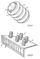
- the gas fire constructed according to the present invention and illustrated in Figs. 1, 2 and 3 of the accompanying drawings, comprises a hollow generally cylindrical heat exchanger element 1 made of aluminium, with three groups 3 of three generally radially projecting fins 5 which extend axially of the element 1.
- the heat exchanger element 1 is formed by extrusion, the extrusion being cut to the desired length and the end regions machined to form axial extensions 7 for use in sealingly mounting the element 1 in a gas fire as shown in Fig.2 of the accompanying drawings.
- a number of the elements 1 are in use located in the top part of a fire 9, between the walls 11 and 13 defining a convection air passage 15.
- the elements 1 each connect the upper region 17 of the front of the fire 9 with the rear region 19 of the fire which is in use sealingly connected with a flue (not shown).
- a flue not shown
- any suitable thermally conductive material can be alternatively used, as can any suitable method of manufacture, e.g. fabrication or die casting.
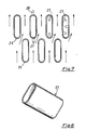
- FIG. 4 An alternative construction of heat exchanger is illustrated in Figs. 4 and 5 of the accompanying drawings.
- This heat exchanger comprises a hollow generally cylindrical element 21 with a number of axially spaced apart, circumferentially extending fins 23 projecting generally radially outwardly from the outside surface thereof.
- these heat exchangers can be integrally formed, e.g. by casting, as part of the convection air passage wall 13 - see Fig.1 between points 'X' and 'Y' - this section of wall being provided with a front facia portion 25 carrying a number of fins 27 for radiating conducted heat from the front of the fire.
- the heat exchanger of Fig. 1 or any other heat exchanger within the scope of the present invention can be formed as part of the wall section X-Y.
- heat exchanger element 25 is shown in Figs. 6 and 7 of the accompanying drawings, the element being formed by a partially flattened tubular element which has a generally oval or lozenge-shaped transverse cross-section.
- These heat exchanger elements 25 are arranged in a gas fire such as shown in part in Fig.1, with the heat exchanger elements relatively positioned as shown in Fig.7, with the narrow cross-section being presented to the air flow. In this way the surface area available for heat transfer is maximised whilst the resistance to air flow is minimised.
- Fins 28, as shown in dashed lines, can be provided one at each end region of the flattened transverse cross-section, to increase surface area and further enhance heat transfer. Alternatively any number of fins can be provided in any desired configuration and arrangement.
- heat transfer can be further enhanced by the provision of fins 29 on the inside wall of the passage through the heat exchangers, said fins extending generally radially inwardly and axially of the passage. Again, any desired number, configuration and/or arrangement of fins 29 can be selected.
- the present invention thus provides an efficient heat exchanger for use in a gas fire, which is both simple and inexpensive to manufacture.
Landscapes
- Engineering & Computer Science (AREA)
- Chemical & Material Sciences (AREA)
- Combustion & Propulsion (AREA)
- Mechanical Engineering (AREA)
- General Engineering & Computer Science (AREA)
- Heat-Exchange Devices With Radiators And Conduit Assemblies (AREA)
Applications Claiming Priority (2)
| Application Number | Priority Date | Filing Date | Title |
|---|---|---|---|
| GB8627216 | 1986-11-14 | ||
| GB868627216A GB8627216D0 (en) | 1986-11-14 | 1986-11-14 | Gas fires |
Publications (2)
| Publication Number | Publication Date |
|---|---|
| EP0267746A2 true EP0267746A2 (fr) | 1988-05-18 |
| EP0267746A3 EP0267746A3 (fr) | 1989-10-04 |
Family
ID=10607329
Family Applications (1)
| Application Number | Title | Priority Date | Filing Date |
|---|---|---|---|
| EP87309822A Withdrawn EP0267746A3 (fr) | 1986-11-14 | 1987-11-06 | Cheminée chauffée par gaz |
Country Status (5)
| Country | Link |
|---|---|
| EP (1) | EP0267746A3 (fr) |
| AU (1) | AU604270B2 (fr) |
| GB (2) | GB8627216D0 (fr) |
| NZ (1) | NZ222523A (fr) |
| PT (1) | PT86126A (fr) |
Families Citing this family (1)
| Publication number | Priority date | Publication date | Assignee | Title |
|---|---|---|---|---|
| GB2238607B (en) * | 1989-12-01 | 1993-11-24 | Brannan Heat Projects Limited | Improvements in or relating to a fitting for a fireplace |
Family Cites Families (7)
| Publication number | Priority date | Publication date | Assignee | Title |
|---|---|---|---|---|
| DE186014C (fr) * | 1905-12-20 | |||
| GB843026A (en) * | 1957-10-04 | 1960-08-04 | R & A Main Ltd | Improvements in or relating to gas fires |
| GB1041223A (en) * | 1962-03-02 | 1966-09-01 | Oatley Technical Dev | Improvements relating to air-warming installations |
| GB1583297A (en) * | 1978-05-23 | 1981-01-21 | Baxendale & Sons Ltd Richard | Gas burning appliances |
| GB2123944A (en) * | 1982-07-22 | 1984-02-08 | Dennis Beardmore | Heating air in fuel-effect gas fires |
| GB8512779D0 (en) * | 1985-05-21 | 1985-06-26 | Hill Ltd J & R | Domestic fires |
| GB8515257D0 (en) * | 1985-06-17 | 1985-07-17 | Taylor Economic Ltd | Gas fire |
-
1986
- 1986-11-14 GB GB868627216A patent/GB8627216D0/en active Pending
-
1987
- 1987-11-04 GB GB08725808A patent/GB2197451A/en not_active Withdrawn
- 1987-11-06 EP EP87309822A patent/EP0267746A3/fr not_active Withdrawn
- 1987-11-12 AU AU81145/87A patent/AU604270B2/en not_active Ceased
- 1987-11-12 PT PT8612687A patent/PT86126A/pt not_active Application Discontinuation
- 1987-11-12 NZ NZ22252387A patent/NZ222523A/en unknown
Also Published As
| Publication number | Publication date |
|---|---|
| GB2197451A (en) | 1988-05-18 |
| EP0267746A3 (fr) | 1989-10-04 |
| AU604270B2 (en) | 1990-12-13 |
| PT86126A (pt) | 1988-12-15 |
| GB8627216D0 (en) | 1986-12-17 |
| AU8114587A (en) | 1988-05-19 |
| GB8725808D0 (en) | 1987-12-09 |
| NZ222523A (en) | 1990-12-21 |
Similar Documents
| Publication | Publication Date | Title |
|---|---|---|
| CA2054900A1 (fr) | Echangeur de chaleur tubulaire perfectionne | |
| KR870010373A (ko) | 전열핀 | |
| JP2735310B2 (ja) | 熱交換器 | |
| JP2769699B2 (ja) | 軸対称斜流式貫流ボイラー | |
| GB2197451A (en) | Gas fires | |
| WO1990013785A1 (fr) | Radiateurs | |
| HU222869B1 (hu) | Hőcserélő egység | |
| JPS5712296A (en) | Corrugated fin for heat exchanger | |
| JP3350104B2 (ja) | 伝熱管 | |
| JPS632792Y2 (fr) | ||
| US5529118A (en) | Heat exchange system for vehicles and heat exchanger therefor | |
| JP3038627B2 (ja) | 水管ボイラ | |
| EP0122667A1 (fr) | Echangeur de chaleur et chaudière de chauffage central avec un tel échangeur de chaleur | |
| US2886295A (en) | Heat exchanger for warm air furnaces | |
| JPH01147253A (ja) | 温風暖房装置 | |
| GB2111667A (en) | Heat exchanger | |
| JPS5924140A (ja) | 熱交換器 | |
| JPH0612325Y2 (ja) | 多管式ボイラにおけるヒレ付水管のヒレ形状 | |
| JPS6082785A (ja) | 熱交換器 | |
| JP2601367Y2 (ja) | 熱交換器 | |
| JPH0564667U (ja) | 給湯機の熱交換器 | |
| JPH02114864U (fr) | ||
| JPS6352061U (fr) | ||
| JPS6232930U (fr) | ||
| JPH0417261U (fr) |
Legal Events
| Date | Code | Title | Description |
|---|---|---|---|
| PUAI | Public reference made under article 153(3) epc to a published international application that has entered the european phase |
Free format text: ORIGINAL CODE: 0009012 |
|
| AK | Designated contracting states |
Kind code of ref document: A2 Designated state(s): AT BE CH DE ES FR GB GR IT LI LU NL SE |
|
| PUAL | Search report despatched |
Free format text: ORIGINAL CODE: 0009013 |
|
| AK | Designated contracting states |
Kind code of ref document: A3 Designated state(s): AT BE CH DE ES FR GB GR IT LI LU NL SE |
|
| RHK1 | Main classification (correction) |
Ipc: F24C 1/14 |
|
| 17P | Request for examination filed |
Effective date: 19900316 |
|
| 17Q | First examination report despatched |
Effective date: 19900917 |
|
| STAA | Information on the status of an ep patent application or granted ep patent |
Free format text: STATUS: THE APPLICATION IS DEEMED TO BE WITHDRAWN |
|
| 18D | Application deemed to be withdrawn |
Effective date: 19910529 |
|
| RIN1 | Information on inventor provided before grant (corrected) |
Inventor name: CONSTABLE, ALAN Inventor name: WRIGHT, PETER Inventor name: SMITH, MARTIN LESLIE Inventor name: HINTON, ALAN VICTOR Inventor name: WHITEHOUSE, DONALD Inventor name: MORAN, CHARLES |