EP0267763A2 - Procédé et appareil pour le montage des barres d'armature arquées horizontales - Google Patents
Procédé et appareil pour le montage des barres d'armature arquées horizontales Download PDFInfo
- Publication number
- EP0267763A2 EP0267763A2 EP87309882A EP87309882A EP0267763A2 EP 0267763 A2 EP0267763 A2 EP 0267763A2 EP 87309882 A EP87309882 A EP 87309882A EP 87309882 A EP87309882 A EP 87309882A EP 0267763 A2 EP0267763 A2 EP 0267763A2
- Authority
- EP
- European Patent Office
- Prior art keywords
- race
- slip
- horizontal
- wall
- rods
- Prior art date
- Legal status (The legal status is an assumption and is not a legal conclusion. Google has not performed a legal analysis and makes no representation as to the accuracy of the status listed.)
- Ceased
Links
Images


Classifications
-
- E—FIXED CONSTRUCTIONS
- E04—BUILDING
- E04G—SCAFFOLDING; FORMS; SHUTTERING; BUILDING IMPLEMENTS OR AIDS, OR THEIR USE; HANDLING BUILDING MATERIALS ON THE SITE; REPAIRING, BREAKING-UP OR OTHER WORK ON EXISTING BUILDINGS
- E04G11/00—Forms, shutterings, or falsework for making walls, floors, ceilings, or roofs
- E04G11/06—Forms, shutterings, or falsework for making walls, floors, ceilings, or roofs for walls, e.g. curved end panels for wall shutterings; filler elements for wall shutterings; shutterings for vertical ducts
- E04G11/20—Movable forms; Movable forms for moulding cylindrical, conical or hyperbolical structures; Templates serving as forms for positioning blocks or the like
- E04G11/22—Sliding forms raised continuously or step-by-step and being in contact with the poured concrete during raising and which are not anchored in the hardened concrete; Arrangements of lifting means therefor
-
- E—FIXED CONSTRUCTIONS
- E04—BUILDING
- E04G—SCAFFOLDING; FORMS; SHUTTERING; BUILDING IMPLEMENTS OR AIDS, OR THEIR USE; HANDLING BUILDING MATERIALS ON THE SITE; REPAIRING, BREAKING-UP OR OTHER WORK ON EXISTING BUILDINGS
- E04G21/00—Preparing, conveying, or working-up building materials or building elements in situ; Other devices or measures for constructional work
- E04G21/12—Mounting of reinforcing inserts; Prestressing
-
- E—FIXED CONSTRUCTIONS
- E04—BUILDING
- E04G—SCAFFOLDING; FORMS; SHUTTERING; BUILDING IMPLEMENTS OR AIDS, OR THEIR USE; HANDLING BUILDING MATERIALS ON THE SITE; REPAIRING, BREAKING-UP OR OTHER WORK ON EXISTING BUILDINGS
- E04G21/00—Preparing, conveying, or working-up building materials or building elements in situ; Other devices or measures for constructional work
- E04G21/12—Mounting of reinforcing inserts; Prestressing
- E04G2021/127—Circular prestressing of, e.g. columns, tanks, domes
Definitions
- This invention relates to the construction of reinforced concrete walls, in particular curved walls such as those of above-ground silos or in-ground tanks or the like.
- Such walls are conventionally constructed with the aid of a slip-form which defines at least the inner surface of a wall-space into which the concrete is poured, and which is raised progressively as the poured concrete hardens.
- the slip-form also supports a working platform for the operators, who position reinforcing and pour the concrete.
- the reinforcing in such walls is a structure comprising an array of vertical rods and an array of horizontal rings of rods spaced one above the other and secured to the vertical rods.
- the reinforcing in such walls is a structure comprising an array of vertical rods and an array of horizontal rings of rods spaced one above the other and secured to the vertical rods.
- the slip-form as a whole is normally supported by a plurality of yokes extending upwards and into the wall space to engage jacks usually secured to or operating on previously emplaced vertical rods.
- the slip-form may be raised by those jacks as the wall is built.
- slip-form could be raised by means which do not attach to yokes.
- any other upwardly extending support or guide members such as those required to support the formwork or prevent lateral movement of the slip-form as it is raised may be utilized in the invention to provide a mechanism which assists in positioning the horizontal reinforcement rods.
- a slip-form for defining at least one surface of a wall-space into which reinforcing rods are located at selected positions to form a reinforcing structure and concrete poured, the slip-form including a plurality of spaced apart upwardly extending members, and roller assemblies releasably engaged with at least some of the members to form within said space a height adjustable horizontal race and an inclined race feeding down to said horizontal race, said inclined race being adapted to transport reinforcing rods into the horizontal race for onward transport to a location adjacent to the selected position in the reinforcing structure.
- roller assemblies comprise rollers mounted in brackets which are releasably engageable with racks secured to the upwardly extending members.
- a vertical pin is mounted at the distal end of each bracket in order to prevent the reinforcing rods from coming off the race.
- roller assemblies releasably engage with the upwardly extending members associated with the slip-form defining the inner surface of a curved wall.
- a skid channel may advantageously be provided along the horizontal race in the region of the intersection with the inclined race.
- at least one motorised roller may be provided at the upper end of the inclined race to assist with feeding the reinforcing rods.
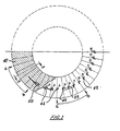
- a slip-form of substantially conventional construction includes vertical support members 1 to 40 (only some of which are shown) which locate formwork 41 (shown in Figure 3 only) that defines the inner surface of a cylinderical wall to be constructed.
- the members 1-40 are disposed spaced about the edge of the area to be bounded by the wall.
- the outer surface of the wall to be constructed can also be formed by slip-form formwork or can be formed by an earthen wall formed by excavation for an inground structure. Prior to the pouring of concrete reinforcing rods are located at selected positions in the defined wall space to form a reinforcing structure as will be described in greater detail below.
- a working deck (not shown) can be associated with the slip form in the conventional manner and raised or lowered up and down support members 1-40 in order to provide a convenient working platform.
- a further upper deck 42 also forms part of the slip form.
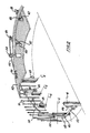
- a plurality of roller assemblies 43, 44 are releaseably engaged with support members to form two races.
- a first race formed by rollers 43 is a generally horizontal race extending around the annular wall-space.
- a second race includes rollers 44 is an inclined feed race which feeds onto the horizontal race.
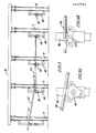
- the rollers are mounted in brackets 45 which are releasably connected to the vertical support columns. Preferably this is achieved by means of the roller brackets 45 being mounted in a removable manner to any selected one of a range of attachment points on racks 46 which extend vertically up the slip-form support column. The rollers extending away from the support columns and into the wall-space.
- the racks 46 are provided in at least two different lengths, short racks which are used to support rollers comprising only the work-race, and longer racks which are used on columns where it is desired to mount rollers for the work race and feed-race.
- the shorter racks 46 are long enough to enable the rollers to be moved up and down sufficiently to cover the range of heights at which horizontal reinforcement rods are to be installed.
- the longer racks 46 are long enough to reach from the lowest work race to the overhead deck.
- the racks preferably have pins (not shown) projecting out of either side and a hole (not shown) in the surface which faces attached roller brackets 45.
- the roller brackets 45 have two hooks for engagement with the pins and a lug (not shown) which locates in the hole in the facing surface of the rack.
- the racks may be provided with holes all along the facing surface and pins all along either side, or the pins may be removable and only inserted when a bracket is to be attached.
- the racks are attached more or less in line with the support columns and the brackets extend laterally out of the line of the columns.
- Blocks 47 which have a flat storage portion 48 adjacent a roller 49 are located on the upper deck 42. Blocks 47 are positioned such that rollers 49 form a curved path leading through an opening 50 in the deck to inclined feed race formed by rollers 44.
- the reinforcing structure within the wall-space is formed as follows.
- Vertical reinforcing rods indicated generally by 51, are positioned in the wall-space defined by the slip-form in the known manner. This is often done prior to location of the slip form.
- Pre-curved sections of horizontal reinforcing rods 52 are brought to the site and stacked, for instance by a crane, on flat portion 48 of blocks 47 on the upper deck 42.
- these reinforcing rods are pushed onto rollers 49 mounted on the blocks and then transported in a curved path around the deck and directed through opening 50 to the rollers 55 forming the inclined or feed race.
- the sections 52 pass down feed race and onto the horizontal race formed by rollers 43 for onward transport to a selected position adjacent the vertical reinforcing rods.
- the horizontal rod sections 52 are then pushed off the rollers and offered up and connected to the vertical rods by, for instance, welding.
- skid channel 53 at least in the region where the two races intersect. This may comprise some straight flat girders or bars.
- the skid channel 53 catches the ends of the reinforcement rods as they have to change direction at the bottom of the feed-race.
- roller arrangements are used in place of the skid channel.
- a tripple roller 55 arrangement as shown in Figure 5a is used on support member 5 in place of roller 43 and dual roller arrangements 56 as shown in Figure 5b are used on support members 6 and 7.
- a pair of motorised rollers 54 arranged like a mangle my be used to grip and propel the reinforcement rods 52.
- This motorised feeder is preferably located in the region of the opening 50 in the upper deck 42 so that workmen may feed the reinforcement rods through the motorised rollers and onto the feed race.
- the purpose of the motorised feeder is to control the rate of decent of reinforcement rods down the inclined race. It is preferred that the motorised feeder has the capacity to also stop or reverse the rods if feeding difficulties are encountered.
- Another preferred feature is to provide vertical pins 55 on the distal ends of the roller brackets 45 in order to ensure that the reinforcing rods 52 will stay on the rollers as they move along.
- the pins are designed to be removable or at least pivoted so that they may be moved out of the way and allow the rods to be slid sideways off the rollers when they arrive at their destinations.
- feed-race and more than one work-race may be installed and operated simultaneously.
- the racks 46 are preferably designed to engage with the support columns associated with the inner slip-form, since in this way the same equipment can be used in the construction of above-ground and in-ground walls.
- rollers composing the races may be mounted and attached in innumerable different ways as will be apparent to those skilled in the relevant art.
- the invention is not restricted to use with the positioning of pre-curved sections of horizontal reinforcing rods, and the rods may even be straight provided they are flexible enough to be curved to the contour of the wall.
Landscapes
- Engineering & Computer Science (AREA)
- Architecture (AREA)
- Mechanical Engineering (AREA)
- Civil Engineering (AREA)
- Structural Engineering (AREA)
- Forms Removed On Construction Sites Or Auxiliary Members Thereof (AREA)
- On-Site Construction Work That Accompanies The Preparation And Application Of Concrete (AREA)
Applications Claiming Priority (2)
| Application Number | Priority Date | Filing Date | Title |
|---|---|---|---|
| AUPH888086 | 1986-11-10 | ||
| AU8880/86 | 1986-11-10 |
Publications (2)
| Publication Number | Publication Date |
|---|---|
| EP0267763A2 true EP0267763A2 (fr) | 1988-05-18 |
| EP0267763A3 EP0267763A3 (fr) | 1989-02-22 |
Family
ID=3771882
Family Applications (1)
| Application Number | Title | Priority Date | Filing Date |
|---|---|---|---|
| EP87309882A Ceased EP0267763A3 (fr) | 1986-11-10 | 1987-11-09 | Procédé et appareil pour le montage des barres d'armature arquées horizontales |
Country Status (4)
| Country | Link |
|---|---|
| US (1) | US4799872A (fr) |
| EP (1) | EP0267763A3 (fr) |
| AU (1) | AU611865B2 (fr) |
| PH (1) | PH24389A (fr) |
Cited By (1)
| Publication number | Priority date | Publication date | Assignee | Title |
|---|---|---|---|---|
| CN111172995A (zh) * | 2020-01-14 | 2020-05-19 | 赵利 | 一种基坑支护的施工工艺 |
Families Citing this family (3)
| Publication number | Priority date | Publication date | Assignee | Title |
|---|---|---|---|---|
| US5558823A (en) * | 1993-04-09 | 1996-09-24 | Gray; Leroy D. | Method for forming walls |
| JP5723174B2 (ja) * | 2011-02-25 | 2015-05-27 | 任天堂株式会社 | 情報処理プログラム、情報処理システム、情報処理装置、および情報処理方法 |
| DE102022205612A1 (de) | 2022-06-01 | 2023-12-07 | Doka Gmbh | Gleitschalung und Verfahren zur Herstellung eines Betonkörpers |
Family Cites Families (5)
| Publication number | Priority date | Publication date | Assignee | Title |
|---|---|---|---|---|
| US887255A (en) * | 1906-06-19 | 1908-05-12 | Olof Kjellstroem | Manufacture of concrete and like pipes. |
| US1134202A (en) * | 1912-04-23 | 1915-04-06 | Alexander V Jensen | Apparatus for making cement pipes. |
| US2579183A (en) * | 1943-06-29 | 1951-12-18 | Freysainet Eugene | Method for tensioning reinforcements |
| NL161225C (nl) * | 1975-12-18 | 1980-01-15 | Ballast Nedam Groep Nv | Werkwijze voor het vervaardigen van een bouwwerk. |
| SU1046104A1 (ru) * | 1982-06-15 | 1983-10-07 | Институт Строительства И Архитектуры Госстроя Бсср | Устройство дл формовани трубчатых изделий из бетонных смесей |
-
1987
- 1987-11-09 US US07/118,730 patent/US4799872A/en not_active Expired - Fee Related
- 1987-11-09 EP EP87309882A patent/EP0267763A3/fr not_active Ceased
- 1987-11-09 AU AU80942/87A patent/AU611865B2/en not_active Ceased
- 1987-11-10 PH PH36052A patent/PH24389A/en unknown
Cited By (1)
| Publication number | Priority date | Publication date | Assignee | Title |
|---|---|---|---|---|
| CN111172995A (zh) * | 2020-01-14 | 2020-05-19 | 赵利 | 一种基坑支护的施工工艺 |
Also Published As
| Publication number | Publication date |
|---|---|
| AU611865B2 (en) | 1991-06-27 |
| US4799872A (en) | 1989-01-24 |
| AU8094287A (en) | 1988-05-12 |
| PH24389A (en) | 1990-06-13 |
| EP0267763A3 (fr) | 1989-02-22 |
Similar Documents
| Publication | Publication Date | Title |
|---|---|---|
| US4071988A (en) | Core and beam suspension system for a building construction and method of construction | |
| US4974700A (en) | Movable support mechanism for construction of elevator shafts and the like | |
| US2993679A (en) | Hoisting apparatus for cylindrical tanks | |
| US4799872A (en) | Slipform apparatus for emplacing horizontal arcuate re-inforcing rods | |
| CN115045507A (zh) | 一种井道支座循环爬升式混凝土布料机 | |
| US3689019A (en) | Apparatus for shuttering poured concrete structures | |
| US3699688A (en) | Apparatus and method for removing and/or adding column sections to a column of a marine structure | |
| KR910001393B1 (ko) | 케이싱과 그 케이싱을 물바닥에 설치하는 방법 | |
| US6030150A (en) | Method and apparatus for constructing subterranean walls comprised of granular material | |
| US20060045720A1 (en) | Method of fabricating a tall multi-stage work piece | |
| US20020042981A1 (en) | System for lifting and assembling re-bar cages | |
| AU705217B2 (en) | Method and apparatus for forming cages | |
| US5590978A (en) | Elevator construction for the launching and recovery of personal watercraft | |
| US4824292A (en) | Support for building structures | |
| US4272465A (en) | Method for multi-storied concrete construction and apparatus therefor | |
| JPH0390777A (ja) | コンクリート打設方法及び装置 | |
| JPS6278359A (ja) | コンクリ−ト垂直打設工法および打設装置 | |
| EP0631018A1 (fr) | Dispositif de coulée en couches d'une masse fluide et durcissable sous l'eau | |
| JP3080772B2 (ja) | トンネル掘削装置 | |
| JPH07158255A (ja) | 昇降式作業足場装置 | |
| JP3341195B2 (ja) | 底型枠取付装置 | |
| JP6917113B2 (ja) | ベルトコンベアラインの昇降装置 | |
| JPH047429B2 (fr) | ||
| KR960002379B1 (ko) | 역타설 무지보 지하구조물 구축장치와 이를 이용한 구축공법 | |
| DE1287596B (de) | Vorrichtung zum abschnittsweisen Herstellen von auf Pfeilern abgestuetzten UEberbauten von Bruecken aus Ortbeton |
Legal Events
| Date | Code | Title | Description |
|---|---|---|---|
| PUAI | Public reference made under article 153(3) epc to a published international application that has entered the european phase |
Free format text: ORIGINAL CODE: 0009012 |
|
| AK | Designated contracting states |
Kind code of ref document: A2 Designated state(s): AT BE CH DE FR GB IT LI LU NL SE |
|
| PUAL | Search report despatched |
Free format text: ORIGINAL CODE: 0009013 |
|
| AK | Designated contracting states |
Kind code of ref document: A3 Designated state(s): AT BE CH DE FR GB IT LI LU NL SE |
|
| 17P | Request for examination filed |
Effective date: 19890810 |
|
| 17Q | First examination report despatched |
Effective date: 19900720 |
|
| STAA | Information on the status of an ep patent application or granted ep patent |
Free format text: STATUS: THE APPLICATION HAS BEEN REFUSED |
|
| 18R | Application refused |
Effective date: 19910715 |