EP0267834A1 - Nach Belieben in Steckkontakt oder -dose umwandelbarer Stecker - Google Patents
Nach Belieben in Steckkontakt oder -dose umwandelbarer Stecker Download PDFInfo
- Publication number
- EP0267834A1 EP0267834A1 EP87402361A EP87402361A EP0267834A1 EP 0267834 A1 EP0267834 A1 EP 0267834A1 EP 87402361 A EP87402361 A EP 87402361A EP 87402361 A EP87402361 A EP 87402361A EP 0267834 A1 EP0267834 A1 EP 0267834A1
- Authority
- EP
- European Patent Office
- Prior art keywords
- socket
- pins
- central body
- metal
- pin
- Prior art date
- Legal status (The legal status is an assumption and is not a legal conclusion. Google has not performed a legal analysis and makes no representation as to the accuracy of the status listed.)
- Withdrawn
Links
- 239000002184 metal Substances 0.000 claims abstract description 19
- 230000001681 protective effect Effects 0.000 claims abstract description 15
- 230000007935 neutral effect Effects 0.000 claims description 9
- 229920003023 plastic Polymers 0.000 claims description 3
- 238000004519 manufacturing process Methods 0.000 description 2
- 239000000463 material Substances 0.000 description 2
- 230000000712 assembly Effects 0.000 description 1
- 238000000429 assembly Methods 0.000 description 1
- 230000000694 effects Effects 0.000 description 1
- 238000003780 insertion Methods 0.000 description 1
- 230000037431 insertion Effects 0.000 description 1
- 238000009434 installation Methods 0.000 description 1
- 238000012986 modification Methods 0.000 description 1
- 230000004048 modification Effects 0.000 description 1
- 230000000717 retained effect Effects 0.000 description 1
- 230000009466 transformation Effects 0.000 description 1
Images


Classifications
-
- H—ELECTRICITY
- H01—ELECTRIC ELEMENTS
- H01R—ELECTRICALLY-CONDUCTIVE CONNECTIONS; STRUCTURAL ASSOCIATIONS OF A PLURALITY OF MUTUALLY-INSULATED ELECTRICAL CONNECTING ELEMENTS; COUPLING DEVICES; CURRENT COLLECTORS
- H01R27/00—Coupling parts adapted for co-operation with two or more dissimilar counterparts
Definitions
- the present invention relates to sockets which can be transformed at will into a male or female socket.
- the present invention overcomes this drawback by providing an outlet characterized in that it essentially comprises: - an electric power supply; - a central body provided with metal tubular passages or ferrules in which metal pins can be inserted; - a support of metal pins; - means for locking the central body on at least one metal pin in two positions: . a first position where the pins protrude outside the main body by constituting a male plug, and . a second position where the pins remain inside the main body constituting a socket; - a protective envelope to insulate the metal parts from the outside.
- the locking means consist of a locking cylinder which, placed in a bore of the central body, cooperates with one of the notches of a neutral pin and with the protective casing to keep the locking cylinder in place, when the central body is locked in the chosen position.
- the metal pins are provided on their rear parts with threaded rods intended to pass through passages formed in the cylindrical wall forming the bottom of the protective envelope.
- the power supply unit includes a cap which surrounds a clamping ring of the power cable in which are embedded three conductive wires carrying lugs which can be fixed on the threaded rods by means of nuts.
- the protective envelope is made of transparent plastic to make the threaded rods visible and thus facilitate their insertion into the bottom of the protective cover.
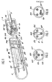
- the socket outlet essentially comprises a power supply unit 1, a central body 3, a support for metal pins 6 and a protective casing 5 of cylindrical shape.
- the power supply unit 1 comprises a cable 7 in which are incorporated three conductive wires 9, 10, 11 carrying at their free ends of terminals 9 ⁇ , 10 ⁇ , 11 ⁇ , the terminals 9 ⁇ and 10 ⁇ being less large than the terminal 11 ⁇ which corresponds to a larger neutral pin.
- the cable 7 is held in place in the center of the power supply by means of a clamping ring 12 housed inside a cap 14 of the power supply and as can be seen in FIG. 2, the cable 7 is fixed firmly in the ring 12 by means of a screw 16.
- the pin support 6 is a cylindrical element crossed axially by two metal pins 18 of sign + or - and a neutral metal pin 20. It can be observed that this neutral pin has at its base two notches 22 and 23 spaced apart from one another. the other so as to allow the assemblies indicated below. In addition, each pin is threaded at its rear part. This is how we distinguish the threaded rods 35, 36, 37.
- the central body 3 is cylindrical, full and traversed by three longitudinal metal ferrules 25, 26, 27 with a diameter just greater than the outside diameters of the pins which correspond to them. It can be noted, axially and in the vicinity of one end of the central body, the presence of a bore 29 designed to receive a locking cylinder 40.
- the protective envelope 5 is a hollow cylindrical body, preferably transparent, in order to be able to observe the position of the threaded rods of the pins and thus facilitate assembly as will be seen below.
- This envelope is closed at one of its ends by a cylindrical wall 15 carrying two passages 30 and a passage 32 with a diameter corresponding to the external diameters of the threaded rods of the pins.
- the outlet has two + or - sockets introduced into the ferrules 25 and 26 and a neutral socket of rectangular shape introduced into a corresponding ferrule 27 ⁇ .
- a locking cylinder 70 pressed into a notch of the rectangular pin in order to effect a locking similar to that obtained in the case of the locking cylinder 40.
- the socket has three pins + or - inserted in ferrules 50, 51, 52 and a neutral socket introduced in a ferrule 53, the locking cylinder 60 being inserted in a notch the neutral pin.
- the mounting of the socket can be carried out as follows with particular reference to Figures 4 to 6.
- the central body 3 and the pin support 6 are made to penetrate one another by introducing the three pins into the three ferrules 25, 26, 27 until the bore 29 arrives just in line of the notch 22.
- the locking cylinder 40 is then introduced into the bore 29 by lowering it until it touches the bottom of the notch as shown in FIG. 5.
- the desired locking is then obtained. It can be noted that the front ends of the pins are retained in the ferrules inside the central body.
- the empty part of each ferrule constitutes a female socket into which a male pin can penetrate.
- the protective casing 5 is then introduced as far as possible, suitably presenting the wall 15 so that the three threaded parts of the pins 35, 36, 37 respectively penetrate into the corresponding passages 30, 32. It is then possible to fix the three lugs to the means of nuts, it is then enough to set up and fix the power supply unit by screwing the cap 14 on an external thread 38 provided on the periphery of the wall 15. The assembly of the socket-outlet was thus carried out in female socket (figure 5).
- the number of metal pins is not limited to three or four and the protective casing of the socket can be made of a material other than a plastic and possibly be of an opaque material. .
Landscapes
- Connector Housings Or Holding Contact Members (AREA)
- Details Of Connecting Devices For Male And Female Coupling (AREA)
Applications Claiming Priority (2)
| Application Number | Priority Date | Filing Date | Title |
|---|---|---|---|
| FR8614673 | 1986-10-22 | ||
| FR8614673A FR2605808B1 (fr) | 1986-10-22 | 1986-10-22 | Prise de courant transformable a volonte en prise male ou femelle |
Publications (1)
| Publication Number | Publication Date |
|---|---|
| EP0267834A1 true EP0267834A1 (de) | 1988-05-18 |
Family
ID=9340079
Family Applications (1)
| Application Number | Title | Priority Date | Filing Date |
|---|---|---|---|
| EP87402361A Withdrawn EP0267834A1 (de) | 1986-10-22 | 1987-10-21 | Nach Belieben in Steckkontakt oder -dose umwandelbarer Stecker |
Country Status (2)
| Country | Link |
|---|---|
| EP (1) | EP0267834A1 (de) |
| FR (1) | FR2605808B1 (de) |
Citations (3)
| Publication number | Priority date | Publication date | Assignee | Title |
|---|---|---|---|---|
| US1516581A (en) * | 1922-11-02 | 1924-11-25 | Seufert Hermann | Electric contact plug |
| US2796591A (en) * | 1955-08-30 | 1957-06-18 | Carter | Electrical connector |
| FR1499288A (fr) * | 1966-08-30 | 1967-10-27 | Fiche électrique mâle et femelle |
-
1986
- 1986-10-22 FR FR8614673A patent/FR2605808B1/fr not_active Expired
-
1987
- 1987-10-21 EP EP87402361A patent/EP0267834A1/de not_active Withdrawn
Patent Citations (3)
| Publication number | Priority date | Publication date | Assignee | Title |
|---|---|---|---|---|
| US1516581A (en) * | 1922-11-02 | 1924-11-25 | Seufert Hermann | Electric contact plug |
| US2796591A (en) * | 1955-08-30 | 1957-06-18 | Carter | Electrical connector |
| FR1499288A (fr) * | 1966-08-30 | 1967-10-27 | Fiche électrique mâle et femelle |
Also Published As
| Publication number | Publication date |
|---|---|
| FR2605808A1 (fr) | 1988-04-29 |
| FR2605808B1 (fr) | 1989-09-08 |
Similar Documents
| Publication | Publication Date | Title |
|---|---|---|
| CA2030725C (fr) | Boitier metallique pour connecteur electrique | |
| EP0521751B1 (de) | Vorrichtung zur Herstellung von Abzweigungen von geschirmten Kabeln | |
| FR2559963A1 (fr) | Connecteur electrique pour cable coaxial | |
| FR2649778A3 (fr) | Indicateur optique, en particulier a usage industriel | |
| EP0055188A1 (de) | Elektrischer Verbinder für Koaxialkabel und Zweileiterkabel | |
| EP3605749B9 (de) | Halterung für ein elektrisches gerät und entsprechendes elektrisches gerät | |
| FR2791185A1 (fr) | Connecteur basse tension pourvu d'un adaptateur et adaptateur pour un tel connecteur | |
| FR2527004A1 (fr) | Porte-fusible | |
| FR3051079A1 (fr) | Dispositif de verrouillage pour connecteurs electriques et connecteurs electriques equipes du dispositif. | |
| FR2738406A1 (fr) | Prise electrique pourvue d'un etrier | |
| EP0805605B1 (de) | Abzweigverbinder für Übertragungsnetze, insbesondere für die Telephonie und Datenverarbeitung | |
| FR2674693A1 (fr) | Dispositif electrique. | |
| FR2605808A1 (fr) | Prise de courant transformable a volonte en prise male ou femelle | |
| FR2612688A1 (fr) | Porte-fusible electrique protege contre tout contact exterieur | |
| FR2551930A1 (fr) | Unite fonctionnelle pour un appareil a moteur electrique tel qu'un outil motorise ou un appareil electromenager; appareil a moteur electrique mettant en oeuvre une telle unite; composant et procede pour la fabrication d'une telle unite | |
| FR2703192A1 (fr) | Assemblage d'un connecteur à fiche et d'une prise complémentaire pour câble coaxial. | |
| EP0091867A1 (de) | Elektrische Verbindereinrichtung mit einem abnehmbaren modulartigen kapazitiven Filtergehäuse | |
| FR2475303A1 (fr) | Structure de bornier pour la connexion de conducteurs electriques pour appareils electriques en general | |
| CH402103A (fr) | Bloc de connexion électrique | |
| EP0299811A1 (de) | Vorgefertigte Stromzuleitung zur Realisierung von elektrischen Verteilungsschaltungen, die steuerbare Verteilungszonen mit verstellbaren Konfigurationen umfassen | |
| FR2716756A1 (fr) | Ensemble perfectionné d'alimentation et de commande, pour un alternateur de véhicule automobile. | |
| EP0395514B1 (de) | Sichereitszusammenbau eines Verbinders und einer Hochspannungslampe, besonders für Wagenbeleuchtung | |
| EP0099384B1 (de) | Flacher elektrischer verbinder mit drei steckstiften | |
| FR2569047A1 (fr) | Porte-fusible antichoc | |
| FR2794525A1 (fr) | Instrument indicateur du type a bobinages croises |
Legal Events
| Date | Code | Title | Description |
|---|---|---|---|
| PUAI | Public reference made under article 153(3) epc to a published international application that has entered the european phase |
Free format text: ORIGINAL CODE: 0009012 |
|
| AK | Designated contracting states |
Kind code of ref document: A1 Designated state(s): BE CH DE ES GB IT LI LU NL |
|
| 17P | Request for examination filed |
Effective date: 19881114 |
|
| STAA | Information on the status of an ep patent application or granted ep patent |
Free format text: STATUS: THE APPLICATION IS DEEMED TO BE WITHDRAWN |
|
| 18D | Application deemed to be withdrawn |
Effective date: 19910502 |