EP0267946B1 - Vorrichtung zur stimulation von gliedversteifungen - Google Patents
Vorrichtung zur stimulation von gliedversteifungen Download PDFInfo
- Publication number
- EP0267946B1 EP0267946B1 EP87903649A EP87903649A EP0267946B1 EP 0267946 B1 EP0267946 B1 EP 0267946B1 EP 87903649 A EP87903649 A EP 87903649A EP 87903649 A EP87903649 A EP 87903649A EP 0267946 B1 EP0267946 B1 EP 0267946B1
- Authority
- EP
- European Patent Office
- Prior art keywords
- plenum
- vacuum
- pump
- housing
- piston
- Prior art date
- Legal status (The legal status is an assumption and is not a legal conclusion. Google has not performed a legal analysis and makes no representation as to the accuracy of the status listed.)
- Expired - Lifetime
Links
- 230000004936 stimulating effect Effects 0.000 title claims abstract description 7
- 210000000260 male genitalia Anatomy 0.000 claims abstract description 5
- 230000003213 activating effect Effects 0.000 claims abstract description 3
- 230000033001 locomotion Effects 0.000 claims description 10
- 239000012530 fluid Substances 0.000 claims description 5
- 238000005192 partition Methods 0.000 claims 3
- 238000007789 sealing Methods 0.000 claims 1
- 210000003899 penis Anatomy 0.000 abstract description 43
- 210000005225 erectile tissue Anatomy 0.000 description 19
- 210000001367 artery Anatomy 0.000 description 15
- 230000017531 blood circulation Effects 0.000 description 14
- 239000008280 blood Substances 0.000 description 10
- 210000004369 blood Anatomy 0.000 description 10
- 210000003462 vein Anatomy 0.000 description 9
- 210000001519 tissue Anatomy 0.000 description 8
- 239000004033 plastic Substances 0.000 description 6
- 229920003023 plastic Polymers 0.000 description 6
- 210000005226 corpus cavernosum Anatomy 0.000 description 5
- 230000024883 vasodilation Effects 0.000 description 4
- 230000006835 compression Effects 0.000 description 3
- 238000007906 compression Methods 0.000 description 3
- 230000000694 effects Effects 0.000 description 3
- 210000005036 nerve Anatomy 0.000 description 3
- 230000002035 prolonged effect Effects 0.000 description 3
- 230000000638 stimulation Effects 0.000 description 3
- 230000033228 biological regulation Effects 0.000 description 2
- 239000007943 implant Substances 0.000 description 2
- 210000003205 muscle Anatomy 0.000 description 2
- 238000005086 pumping Methods 0.000 description 2
- 210000005070 sphincter Anatomy 0.000 description 2
- 210000003708 urethra Anatomy 0.000 description 2
- 208000010228 Erectile Dysfunction Diseases 0.000 description 1
- 230000009471 action Effects 0.000 description 1
- 230000008321 arterial blood flow Effects 0.000 description 1
- 230000008901 benefit Effects 0.000 description 1
- 210000003169 central nervous system Anatomy 0.000 description 1
- 230000000994 depressogenic effect Effects 0.000 description 1
- 230000010339 dilation Effects 0.000 description 1
- 201000010099 disease Diseases 0.000 description 1
- 208000037265 diseases, disorders, signs and symptoms Diseases 0.000 description 1
- 239000000835 fiber Substances 0.000 description 1
- 210000003811 finger Anatomy 0.000 description 1
- 239000007924 injection Substances 0.000 description 1
- 238000002347 injection Methods 0.000 description 1
- 235000015110 jellies Nutrition 0.000 description 1
- 239000008274 jelly Substances 0.000 description 1
- 238000004519 manufacturing process Methods 0.000 description 1
- 239000000463 material Substances 0.000 description 1
- QSHDDOUJBYECFT-UHFFFAOYSA-N mercury Chemical compound [Hg] QSHDDOUJBYECFT-UHFFFAOYSA-N 0.000 description 1
- 229910052753 mercury Inorganic materials 0.000 description 1
- 238000000034 method Methods 0.000 description 1
- 230000004048 modification Effects 0.000 description 1
- 238000012986 modification Methods 0.000 description 1
- 210000004977 neurovascular bundle Anatomy 0.000 description 1
- 231100000862 numbness Toxicity 0.000 description 1
- 230000002093 peripheral effect Effects 0.000 description 1
- 230000008569 process Effects 0.000 description 1
- 210000002307 prostate Anatomy 0.000 description 1
- 230000001107 psychogenic effect Effects 0.000 description 1
- 230000000717 retained effect Effects 0.000 description 1
- 210000004706 scrotum Anatomy 0.000 description 1
- 230000035939 shock Effects 0.000 description 1
- 239000000243 solution Substances 0.000 description 1
- 210000003813 thumb Anatomy 0.000 description 1
- 230000000304 vasodilatating effect Effects 0.000 description 1
Images


Classifications
-
- A—HUMAN NECESSITIES
- A61—MEDICAL OR VETERINARY SCIENCE; HYGIENE
- A61F—FILTERS IMPLANTABLE INTO BLOOD VESSELS; PROSTHESES; DEVICES PROVIDING PATENCY TO, OR PREVENTING COLLAPSING OF, TUBULAR STRUCTURES OF THE BODY, e.g. STENTS; ORTHOPAEDIC, NURSING OR CONTRACEPTIVE DEVICES; FOMENTATION; TREATMENT OR PROTECTION OF EYES OR EARS; BANDAGES, DRESSINGS OR ABSORBENT PADS; FIRST-AID KITS
- A61F5/00—Orthopaedic methods or devices for non-surgical treatment of bones or joints; Nursing devices ; Anti-rape devices
- A61F5/41—Devices for promoting penis erection
-
- A—HUMAN NECESSITIES
- A61—MEDICAL OR VETERINARY SCIENCE; HYGIENE
- A61F—FILTERS IMPLANTABLE INTO BLOOD VESSELS; PROSTHESES; DEVICES PROVIDING PATENCY TO, OR PREVENTING COLLAPSING OF, TUBULAR STRUCTURES OF THE BODY, e.g. STENTS; ORTHOPAEDIC, NURSING OR CONTRACEPTIVE DEVICES; FOMENTATION; TREATMENT OR PROTECTION OF EYES OR EARS; BANDAGES, DRESSINGS OR ABSORBENT PADS; FIRST-AID KITS
- A61F5/00—Orthopaedic methods or devices for non-surgical treatment of bones or joints; Nursing devices ; Anti-rape devices
- A61F5/41—Devices for promoting penis erection
- A61F2005/412—Devices for promoting penis erection by vacuum means
Definitions
- the present invention refers to a surgical apparatus for stimulating an erection of the type as disclosed in the preamble of claim 1.
- the male penis consists mainly of three spongy erectile tissues, two large corpora cavernosa tissues and a smaller corpus spongiosum tissue which insheaths the urethra. Erection of the penis occurs when the spongy erectile tissues are rapidly filled with blood which compresses the veins which ordinarily drain the penis. Blood is retained in the tissues that would normally be drained from the penis causing stiffness or an erection.
- an erection of the penis results from an increased blood flow in the dorsal and profunda arteries flowing into the large corpora cavernosa tissues and an increased blood flow in the bulbo-urethral arteries flowing into the smaller corpus spongiosum tissue.
- Vasodilation of the arteries feeding the erectile tissues may be effected by the central nervous system exciting or activating the neuro vascular bundle of nerves located near the prostate gland behind the scrotum. Local stimulation of the nervous fibers in the penis may also induce vasodilation of the arteries supplying the erectile tissues of the penis.
- Suction apparatuses as shown in US-A-3 744 486, CH-A-347 300, and GB-A-1 497 441 cause a partial vacuum surrounding the penis which includes blood flow into the erectile tissues.
- the apparatus of US-A-3 744 486 shows a pump chamber attached to the sidewall of the vacuum chamber.
- the pump means comprises a piston which slidably engage the sidewall of the pump chamber housing, and being sealed by means of an O-ring with the housing. This arrangement causes loss of efficiency by friction.
- the suction stroke is restricted, at least when the piston rod is to be actuated by a one hand operable lever, since the free end of the lever which is connected to the piston rod moves through an arcuate path about its pivot axis.
- GB-A-1497441 discloses an apparatus in which a diaphragm pump can be used for producing vacuum.
- the diaphragm pump is to be connected to the vacuum housing via a flexible hose connecting the upper end of the vacuum housing to its lower end.
- the pump housing is not connected to the vacuum housing.
- the apparatus has to be attached to the user's body by belts, and cannot be held and operated by one hand.
- the vacuum has to be applied to the vacuum chamber via the long flexible hose which might delay the application of the vacuum in the vacuum chamber, and might prevent sudden application of the vacuum.
- Apparatus employing hypodermic needles for injecting vasodilatory fluids into the corpora cavernosa to dilate the profunda and the dorsal arteries are not desirable because the needles break the skin of the penis exposing the user to harmful or even fatal diseases.
- Such devices require a high degree of skill to effect proper injections and also inflict both pain and psychological shock in the process.
- Further prior art suction devices are also provided with elastic bands which may be transferred from the end of the suction device when some degree of erection is achieved. The elastic band is preferably transferred to the base of the penis to retard blood flow from the erectile tissues, thus, maintaining an erection for a longer time.
- Vibrators devices which cause compression and/or create suction are employed as stimulators to induce blood flow into the erectile tissues.
- Elastic bands, tourniquets, straps and elastic sleeves have also been employed to impede blood flow from the penis once erection is achieved. Some of these latter devices are known to cut off the blood flow from and/or to the penis and can result in damage to nerves and/or tissue.
- the apparatus of the present invention is capable of producing an adjustable vacuum which is sufficiently high to induce an erection in impotent males with psychogenic or physical disfunction in order to provide a lengthing and enlargement of the expanded penis in the flacid state as well as to enlarge the penis size over the normal erect state.
- the present invention further provides a surgical apparatus having a novel durable vacuum seal of an enlarged area which allows greater stroke capacities of the pumping means.
- an elongated surgical appliance having a vacuum housing at one end for loosely receiving therein the male penis, a vacuum pump having a vacuum plenum is connected to the other end of the vacuum housing for providing a high vacuum in the vacuum plenum and vacuum chamber, a pump lever extends along the side wall of the vacuum housing and is connected to the vacuum pump so that it is operable with the same hand which supports the vacuum chamber, such successive operation of the pump lever produces an increasingly higher vacuum in the vacuum chamber to effect blood flow in the erectile tissue and to effect erection of the male penis.
- Fig. 1 showing a cross-section view through a male penis 10.
- the inability of the penis to achieve an erection may be psychological or physiological in nature, however, the immediate cause for the failure to produce an adequate erection results from incomplete inflation of the corpora cavernosa erectile tissue 13 with blood.
- the dorsal arteries 11 and the profunda (or deep penile) arteries 12 will be dilated to increase blood flow to the corpora cavernosa tissue 13.
- the rapid filling of the spongy erectile tissues with blood compresses the veins in the tissues which would ordinarily drain the tissues, thus, resulting in stiffness or erection of the penis.
- the bulbo-urethral artery 14, when dilated, fills the spongy erectile tissues of the corpus spongiosum tissue 15 surrounding the urethra and further enhances stiffness or erection of the penis.
- Superficial dorsal veins 17 and lateral veins 19, as well as deep dorsal vein 18 drain the blood from the erectile tissues. If the flow of the blood is restricted or impeded in the veins, the erection can be prolonged or maintained over a relatively long period.
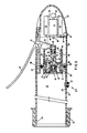
- the appliance 20 comprises a soft seal 21 on the open end of the main vacuum housing 22.
- housing 22 is cylindrical and a rigid clear plastic.
- a pump housing 23 is also cylindrical and connected to the closed end of housing 22.
- a nose cone housing 24 is connected to housing 22 and provides a cover for a vibrator or electric pump drive as will be explained hereinafter.
- the preferred mode of operation of the vacuum pump in housing 23 is by manual operation of lever 25 with the thumb or fingers while holding and operating the appliance 20 with one hand.
- the pump is designed to impart a vibratory motion to the penis which further enhances and stimulates the nerves.
- Fig. 3 showing in elevation the details of a BELLOFRAM® pump in enlarged partial section.
- Soft plastic seal 21 is permanently attached to the open end 26 of housing 22 and is adapted to serve as a vacuum seal against the body at the base of the penis in one mode of operation.
- a resilient relief valve 27 is mounted through a hole 29 in the side of housing 22 and is operable to allow air to enter the vacuum chamber 28 of housing 22 when distorted laterally to uncover a portion of hole 29.
- Lever 25 is pivotally mounted on a pivot pin 31 in pump housing 23.
- the short end of lever 25 is pivotally mounted to a piston rod 32 of piston 33 by pin 30.
- Piston rod 32 has a cylindrical recess 34 in which a check valve plug 35 is free to move.
- a resilient disk seal 36 is cooperable with plug 35 and is adapted to seal conduit 37 during a suction stroke of piston 33.
- the end wall 38 of housing 22 forms a wall of a plenum chamber 40.
- Wall 38 is provided with an aperture or conduit 39 which opens into a cylindrical recess 41 in which a check valve plug 42 is free to move.
- a resilient seal 43 cooperates with plug 42 and is adapted to seal conduit 39 during a return stroke of piston 33.
- BELLOFRAM® disk 46 is shown folded in plenum 40. During the suction stroke, the flexible disk 45 unfolds as piston 33 moves to the right. BELLOFRAM® disk 46 forms a moveable wall of the plenum 40 similar to a bellows. Cap screws 47 in piston 33 hold the inner diameter of disk 46 sealed against piston 33.
- Spring cage 48 of pump housing 23 holds the outer diameter of BELLOFRAM® disk 46 sealed against end wall 38 of vacuum housing 22.
- Tie rods 49 hold the vacuum housing 22, the pump housing 23 and cone housing 24 tightly together and also compress the end ring 50 of BELLOFRAM® disk 46 against end wall 38.
- a desirable feature of the BELLOFRAM® disk 46 is that it permits piston pin 30 to be moved through an arcuate path which tilts piston 33.
- Clamp disk 45 is loosely fitted in spring case 48 which serves as a guide for movement of piston 33.
- BELLOFRAM® disk 46 does not rub against either piston 33 or end wall 38, thus, is not subject to friction wear which could cause loss of the high vacuum seal achieved in the preferred embodiment of the present invention.
- the structure shown has been tested and is capable of achieving vacuum pressures in excess of 0,8bar (twenty-two inches of mercury), which is double the best vacuum pressure achieved with a normal piston employing a moving friction seal against a cylindrical sidewall. Depression of lever 25 starts the suction stroke that eventually creates a vacuum in plenum 40 high enough so that the vacuum in chamber 28 causes valve 42,43 to rapidly open. This rapid opening results in a pulsating and stimulating action which enhances dilation of the arteries.
- a vibrating solenoid 51 may be mounted in the nose cone 24.
- Push button switch 52 is electrically connected to the solenoid 51 and batteries 53 by wires 54 to control operation of the solenoid.
- solenoid 53 is axially aligned with piston rod 32 and may be connected thereto by a shaft or rod 55.
- bumper stop 56 is preferably connected on shaft 55 to limit the travel of the shaft 55, and lever 25 is disconnected from piston rod 32.
- the electric pump feature need not be employed when the patient-user has sufficient manual dexterity to actuate and control lever 25.
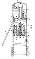
- FIG 4 showing in side elevation an enlarged partial section of a modified embodiment apparatus.
- the figure 4 embodiment has a modified piston 33' that employs a moving friction O-ring seal 57, and a fixed O-ring seal 58, otherwise the parts are the same as those shown in Figure 3 and are numbered the same.
- Nose cone 24' is larger than before and is shaped to receive a small efficient electric motor 60 having an eccentric weight 59 mounted on its rotating shaft 61.
- Adjustment wheel 62 is provided with a wheel contact 63 which engages reostate coil 64.
- Wheel 62 is mounted on the battery and motor support frame 65 and is biased into engagement with coil 64 by spring 66, held in compression by washer 67 and clip 68.
- Wheel contact 63 provides ON-OFF regulation as well as speed adjustment regulation of motor 60.
- Electrical contacts 69 and 70 are shown as connected to the battery and motor, however, the electrical wires which connect the reostat-switch with the motor and battery are well known and are not shown in this illustration.
- motor 60 is speed adjustable by reostate 64 for changing the frequency of the vibratory motion generated by eccentric weight 59.
- the vibration motor 60 is more efficient than a solenoid 51 shown in figure 3.
- motor 60 must be modified if it is desired to drive the short end of lever 27 through a lever and link, not shown in this embodiment. Whenever the motor is modified to drive the piston 33' in a manner shown in Figure 3, vibration is created as a result of the pumping action.
- the hereinbefore described apparatus 20 has a soft end seal 21 which will enable the average user to make a seal against the body in the presence of pubic hair which is sufficient to create an average vacuum. With the aid of surgical jelly even a higher vacuum is achieved in chamber 22. Once an erection is achieved and the apparatus removed, the blood engorged in the erectile tissues may return by venal flow to the body unless the sphincter muscles restrict the return flow. It is known that constricting devices applied to the outside of the penis in the form of a tourniquet will assist in maintaining an erection by restricting the return venal blood flow but the arterial blood flow should be unrestricted.
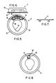
- Ring 71 is adapted to be used with the preferred embodiment apparatus 20 shown in Figures 3 and 4. Unlike most prior art devices, the ring 71 does not of itself exert a radially inward pressure similar to an elastic band or elastic strap but is surgically designed and provided with an interior aperture 74 which is not constrictive when the penis is flacid. Moreover, the novel constriction ring 71 is adapted to be used with the apparatus 20 in one of two preferred modes of operation which will be explained in more detail hereinafter.
- Ring 71 has a radial flange 72 and an axial tapered portion 73 which permits the constriction ring to be mounted onto the male penis before using the apparatus 20, or to be mounted in the apparatus 20 before the flacid penis is induced to full erection with apparatus 20.
- the penis reaches full erection, it enlarges when the arterial blood fills the erectile tissues.
- the enlarge penis presses radially outward on the aperture 74.
- the size and shape of the aperture 74 has been surgically determined to achieve and maintain full erection with the minimum constriction of blood flow in the penis. It has been found that use of the apparatus actually icnreases the diameter and the length of the penis of the average user, and more than one surgical constriction ring is desirable for the average user.
- the interior aperture 74 is not round, but is relieved at portion 75 opposite the bulbo-urethral arteries 14 shown in Figure 1.
- Ring 71 is flexible , but is sufficiently rigid to maintain its desired surgical shape shown without creating excessive pressure on the dorsal arteries 11 or the bulbo-urethral arteries 14.
- Ring 71 may be made in a single continuous molded piece, or provided with a break or split 76 which is preferred.
- the preferred embodiment quick release ring 71 shown in Figure 5 and 6 is provided with a snaplock 79 shown in Figure 7.
- the snaplock 79 is adapted to snap into recesses 78 shown in ring 71.
- Figure 8 shows a modified quick release split lock constriction ring 71' having a lock 79' insert molded integrally with the ring and adapted to snap into recess 81.
- the lock 79' and recess 81 may take any of numerous forms such as a tapered wedge and keystone shapes all of which are adapted to provide a seal to the split 76' and permits the constriction ring 71' to be removed or installed by the user in a flacid or erect state.
- Lever 25' is pivotally mounted on the outside of housing 22'.
- Pin connected lever 82 is connected to piston 83 and is movably mounted in cylinder 84.
- Piston 83 is provided with a seal 85 and a flap check valve 86.
- the base 87 is cross bored to provide a conduit 88 which connects plenum 40 with the vacuum chamber of housing 22'.
- Flap check valve 91 seals off conduit 88 during a return stroke.
- the friction seal 85 tends to wear, leak, expand and stick unless special materials such as anti-friction plastics are employed.
- the advantage of such a device resides in the ease and cheapness of manufacture, thus, making the surgical appliance available to persons who could not ordinarily afford a more reliable and more expensive high vacuum device.
- Plastic bellow 92 may be molded of plastic to provide an easily constructed vacuum pump. Flap check valve 93 is mounted on rigid drive disk 94 and flap check valve 95 is mounted on end wall 96 of vacuum chamber 22''. Lever 97 is driven by a force applied in alternate directions by means discussed hereinbefore. The retainer ring 98 is adapted to hold plastic bellows 92 against end wall 96.
- Figure 9 and 10 are intended to illustrate a basic mode of operation and structure having a very small plenum chamber 40 combined with a tight seal which will enable the apparatus to achieve an average vacuum with a rubbing seal and a high vacuum with a preferred embodiment seal.
- a high vacuum is achieved in the first part of the first suction stroke.
- each successive stroke creates a high vacuum in the plenum which is transferred to the vacuum chamber, rapidly reducing the pressure therein.
- vasodilation occurs immediately.
- the penis fills the constriction ring 71 the compressed veins in the outer peripheral area of the penis are now contracted, thus, maintaining a full erection.
- the apparatus 20 and ring 71 may be assembled before use. When a full hard erection is achieved, the apparatus 20 may be separated from the ring 71 and the full erectile tissues will be expended or exercised. Exercise of the erectile tissues with or without the constriction ring 71 will result in a semi-permanent enlargement of the penis over a short period of time, thus, resulting in a larger and more rigid than normal erection.
- the ring 71 may be placed on the penis before or after a full or partial erection is achieved.
- the erection may have been achieved with or without the use of the apparatus 20.
- Apparatus 20 may be subsequently employed at any time to achieve a full and hard erection.
- the present apparatus now assures that full penile tumescence can be achieved at any time.
Landscapes
- Health & Medical Sciences (AREA)
- Reproductive Health (AREA)
- Nursing (AREA)
- Orthopedic Medicine & Surgery (AREA)
- Engineering & Computer Science (AREA)
- Biomedical Technology (AREA)
- Heart & Thoracic Surgery (AREA)
- Vascular Medicine (AREA)
- Life Sciences & Earth Sciences (AREA)
- Animal Behavior & Ethology (AREA)
- General Health & Medical Sciences (AREA)
- Public Health (AREA)
- Veterinary Medicine (AREA)
- Orthopedics, Nursing, And Contraception (AREA)
- Percussion Or Vibration Massage (AREA)
Claims (17)
- Orthopädischer Apparat zum Stimuliern einer Errektion des männlichen Genitalorgans (10) mit einem langgestreckten, orthopädischen Gerät (20), das ein mit einem Pumpengehäuse (23) verbundenes Vakuumgehäuse (22) aufweist und geeignet ist, mit einer Hand gehalten und betätigt zu werden, wobei das Vakuumgehäuse (22) eine Vakuumkammer (28) und ein offenes, das männliche Genitalorgan (10) aufnehmendes Ende sowie ein geschlossenes Ende (38) aufweist, mit einen Vakuumraum (40) im Pumpengehäuse (23), der mit der Vakuumkammer (28) verbunden ist, eine Vakuumpumpen-Einrichtung (32, 33) im Pumpengehäuse (23), die mit dem Vakuumraum (40) zum Reduzieren des Luftdrucks im Vakuumraum (40) auf einen Wert unterhalb des Luftdrucks in der Vakuumkammer (28) verbunden ist, eine Ventileinrichtung (35, 36, 42, 43) zum abwechselnden Herstellen einer Durchflußverbindung vom Vakuumraun (40) mit: (a) der Vakuumkammer, um Luft aus der Vakuumkammer in den Raum (40) zu bewegen und den Luftdruck in der Vakuumkammer (28) zu reduzieren und (b) mit der Umgebung außerhalb des Raums (40) um Luft aus dem Raum (40) zur Umgebung außerhalb des Raums (40) zu entlassen, und mit einer Einrichtung (25, 51), die im Pumpengehäuse (23) montiert ist, um die Pumpeneinrichtung (32, 33) zu betätigen, dadurch gekennzeichnet, daß das geschlossenen Ende (38) des Vakuumgehäuses (22) und das Ende des Pumpengehäuses (23) aneinander angeordnet sind, und daß die Vakuumpumpen-Einrichtung (32, 33) eine flexible Membran (46) aufweist, die zwischen dem Pumpengehäuse (23) und der Pumpeneinrichtung (32, 33) zum Abdichten der Pumpeneinrichtung (32, 33) zum Vakuumraum (40) angeordnet ist.
- Apparat nach Anspruch 1, dadurch gekennzeichnet, daß die Pumpeneinrichtung (32, 33) eine hin- und hergehende Bewegung unternimmt, und daß die Ventileinrichtung (35, 36, 42, 43) auf die hin- und hergehende Bewegung der Pumpeneinrichtung (32, 33) anspricht, um den Raum (40) in eine Durchflußverbindung zu bringen mit: (a) der Vakuumkammer (28), wenn die Pumpeneinrichtung sich in einer ersten Richtung bewegt, um den Luftdruck in dem Raum (40) auf einen Wert unterhalb des Luftdrucks in der Vakuumkammer (28) zu reduzieren, und (b) dem Umgebungsraum außerhalb des Raums (40), wenn sich die Pumpeneinrichtung (32, 33) in einer zweiten, der ersten Richtung entgegengesetzten Richtung bewegt.
- Apparat nach Anspruch 1 oder 2, dadurch gekennzeichnet, daß sowohl das Vakuumkammergehäuse (22) und das Pumpenkammergehäuse (23) zylindrisch sind, und daß die Betätigungseinrichtung (25, 31) im Pumpenkammergehäuse (23) in einer Stellung montiert ist, wo die Betätigungseinrichtung (25, 51) mit der gleichen Hand des Benutzers des Apparats in Eingriff treten kann, die verwendet wird, um den Apparat zu halten.
- Apparat nach Anspruch 2 oder 3, dadurch gekennzeichnet, daß die Betätigungseinrichtung einen Hebel (25) enthält, der mit der Pumpeneinrichtung (32, 33) zum Bewegen der Pumpeneinrichtung (32, 33) in der ersten Richtung gekoppelt ist, und daß die Pumpeneinrichtung eine Feder (44) enthält, um die Pumpeneinrichtung zu zwingen, sich in die zweite Richtung zu bewegen.
- Apparat nach einem der Ansprüche 1 bis 3, dadurch gekennzeichnet, daß die Betätigungseinrichtung einen elektrischen Antrieb (51) für die Pumpe aufweist, der in einem Gehäuse (24) untergebracht ist, das mit seinem Ende am Ende des Pumpengehäuses (23) angeordnet ist.
- Apparat nach Anspruch 5, dadurch gekennzeichnet, daß ein Druckknopfschalter (52) zum Aktivieren der Pumpeneinrichtung (32, 33) vorgesehen ist.
- Apparat nach einem der Ansprüche 1 bis 6, dadurch gekennzeichnet, daß das geschlossene Ende eine Trennwand (38) aufweist, die die Raumkammer von der Vakuumkammer trennt, und daß die flexible Membran (46) zwischen der Trennwand (38) und der Pumpeneinrichtung (32, 33) angeordnet ist.
- Apparat nach einem der Ansprüche 1 bis 7, dadurch gekennzeichnet, daß die Pumpeneinrichtung einen Kolben (32, 33) aufweist, der sich aus dem Vakuumraum (40) zum Reduzieren des Luftdrucks im Raum (40) auf einen Wert unterhalb Atmosphärendruck herausbewegt, und wobei die Betätigungseinrichtung (25, 51) den Kolben (32, 33) in den Vakuumraum hineinbewegt, um den Luftdruck in dem Vakuumraum (40) auf einen Wert über Atmosphärendruck zu erhöhen.
- Apparat nach Anspruch 7, dadurch gekennzeichnet, daß die Ventileinrichtung enthält: (a) eine erste Ventileinrichtung (42, 43), die in der Trennwand (38) angeordnet ist und (i) auf die Bewegung des Kolbens (32, 33) aus dem Vakuumraum (40) heraus reagiert, um die Vakuumkammer (28) und den Raum (40) in Durchflußverbindung zu bringen, wenn der Luftdruck in der Vakuumkammer (28) den Luftdruck im Raum (40) übersteigt, um den Luftdruck in der Vakuumkammer (28) zu reduzieren, und (ii) auf die Bewegung des Kolbens (32, 33) in den Raum (40) anspricht, um eine Luftströmung zwischen der Vakuumkammer (28) und dem Vakuumraum (40) zu verhindern, wenn der Luftdruck in dem Raum den Luftdruck in der Vakuumkammer (28) übersteigt, und (b) eine zweite Ventileinrichtung (35, 36), die (i) auf die Bewegung des Kolbens (32, 33) aus dem Vakuumraum (40) anspricht, um eine Luftströmung zwischen dem Vakuumraum und der Umgebung außerhalb des Vakuumraums (40) zu verhindern, wenn der Luftdruck im Vakuumraum (40) unterhalb Atmosphärendruck liegt, und (ii) auf die Bewegung des Kolbens (32, 33) in den Vakuumraum (40) hinein anspricht, um den Vakuumraum (40) und die Umgebung außerhalb des Raums in Durchflußverbindung zu bringen, wenn der Luftdruck im Raum auf einem Wert oberhalb Atmosphärendruck liegt, um den Luftdruck im Vakuumraum (40) auf Atmosphärendruck zu reduzieren.
- Apparat nach Anspruch 9, dadurch gekennzeichnet, daß der Kolben (32, 33) eine Luftströmungspassage (39) aufweist, die sich mit einem ersten Ende in den Vakuumraum (40) öffnet, und sich mit einem zweiten Ende in die Umgebung außerhalb des Raums öffnet, und daß die zweite Ventileinrichtung (35, 36) sich in der Luftdurchflußpassage befindet.
- Apparat nach einem der Ansprüche 1 bis 10, dadurch gekennzeichnet, daß die flexible Membran (46) eine flexible Unterlegscheibe ist.
- Apparat nach Anspruch 11, dadurch gekennzeichnet, daß die flexible Unterlegscheibe zu einer flexiblen Wand geformt ist.
- Apparat nach Anspruch 12, dadurch gekennzeichnet, daß die Ventileinrichtung ein Kontrollventil (35, 36) aufweist, das mit dem Vakuumraum (40) durch eine zentrale Öffnung in der flexiblen Unterlegscheibe verbunden ist.
- Apparat nach Anspruch 13, dadurch gekennzeichnet, daß das Kontrollventil (35, 36) im Kolben (32, 33) angeordnet ist.
- Apparat nach einem der Ansprüche 4 bis 14, dadurch gekennzeichnet, daß der Hebel (25) mit dem Kolben (32, 33) durch einen Drehstift (30) verbunden ist.
- Apparat nach einem der Ansprüche 1 bis 15, dadurch gekennzeichnet, daß die Pumpeneinrichtung einen Kolben (33) aufweist, der für eine Hin- und Herbewegung in einem zylindrischen Gehäuse (38, 48) aufgenommen ist, wobei die flexible Membran (46) zwischen dem Kolben (33) und dem Gehäuse (38, 48) angeordnet ist, und einen Spalt zwischen einer äußeren Umfangsfläche des Kolbens (33) und einer inneren Oberfläche des Gehäuses (38, 48) überbrückt.
- Apparat nach Anspruch 16, gekennzeichnet durch eine flexible Scheibe (45), die mit der Pumpeneinrichtung (32, 33) verbunden ist und den Spalt in gleitendem Eingriff mit dem Gehäuse der Scheibe (45) überbrückt.
Priority Applications (1)
| Application Number | Priority Date | Filing Date | Title |
|---|---|---|---|
| AT87903649T ATE79529T1 (de) | 1986-05-14 | 1987-05-14 | Vorrichtung zur stimulation von gliedversteifungen. |
Applications Claiming Priority (2)
| Application Number | Priority Date | Filing Date | Title |
|---|---|---|---|
| US862987 | 1986-05-14 | ||
| US06/862,987 US4741329A (en) | 1986-05-14 | 1986-05-14 | Surgical appliance for stimulating an erection |
Publications (3)
| Publication Number | Publication Date |
|---|---|
| EP0267946A1 EP0267946A1 (de) | 1988-05-25 |
| EP0267946A4 EP0267946A4 (de) | 1988-09-19 |
| EP0267946B1 true EP0267946B1 (de) | 1992-08-19 |
Family
ID=25339940
Family Applications (2)
| Application Number | Title | Priority Date | Filing Date |
|---|---|---|---|
| EP87304239A Withdrawn EP0246080A3 (de) | 1986-05-14 | 1987-05-13 | Chirurgische Hilfsvorrichtung zur Stimulierung einer Erektion |
| EP87903649A Expired - Lifetime EP0267946B1 (de) | 1986-05-14 | 1987-05-14 | Vorrichtung zur stimulation von gliedversteifungen |
Family Applications Before (1)
| Application Number | Title | Priority Date | Filing Date |
|---|---|---|---|
| EP87304239A Withdrawn EP0246080A3 (de) | 1986-05-14 | 1987-05-13 | Chirurgische Hilfsvorrichtung zur Stimulierung einer Erektion |
Country Status (8)
| Country | Link |
|---|---|
| US (1) | US4741329A (de) |
| EP (2) | EP0246080A3 (de) |
| JP (2) | JPS63503364A (de) |
| KR (1) | KR880701095A (de) |
| AU (1) | AU607426B2 (de) |
| CA (1) | CA1276516C (de) |
| DE (1) | DE3781240T2 (de) |
| WO (1) | WO1987006822A1 (de) |
Families Citing this family (37)
| Publication number | Priority date | Publication date | Assignee | Title |
|---|---|---|---|---|
| US4856499A (en) * | 1988-04-11 | 1989-08-15 | Assist Research Corp. | Erection device |
| YU47639B (sh) * | 1989-09-11 | 1995-12-04 | Bvk Konsalting D.O.O. | Aparat za postizanje i održavanje erekcije penisa |
| US5020522A (en) * | 1990-03-08 | 1991-06-04 | Stewart Edward T | Compact vacuum therapy system |
| US5244453A (en) * | 1990-04-03 | 1993-09-14 | Osbon Medical Systems, Inc. | Apparatus for augmenting male potency |
| US5095895A (en) * | 1990-05-11 | 1992-03-17 | Dacomed Corporation | Negative pressure erection apparatus |
| US5083556A (en) * | 1990-05-31 | 1992-01-28 | Osbon Medical Systems, Ltd. | Penile cincture band operational apparatus |
| US5213563A (en) * | 1991-02-04 | 1993-05-25 | Cox Allan J | Apparatus for obtaining an artificial erection |
| US5125890A (en) * | 1991-02-22 | 1992-06-30 | Bak Medical Products | Vacuum-constriction erection aid device |
| US5094230A (en) * | 1991-09-19 | 1992-03-10 | Clark Jr Buford E | Method and apparatus for treating Peyronie's disease |
| USD343455S (en) | 1992-01-10 | 1994-01-18 | Osbon Medical Systems, Ltd. | Male organ conditioning appliance |
| USD346023S (en) | 1992-05-28 | 1994-04-12 | Stewart Sr Edward T | Manually actuated vacuum pump for male sexual disfunction |
| USD345420S (en) | 1992-05-28 | 1994-03-22 | Stewart Sr Edward T | Compact power-actuated male impotency treatment pump |
| US5462514A (en) * | 1992-12-15 | 1995-10-31 | Harris; Jesse | Apparatus for aiding erections in males |
| US5421808A (en) * | 1993-07-30 | 1995-06-06 | Osbon Medical Systems, Ltd. | Battery-operated male organ conditioning appliance |
| US5460594A (en) * | 1994-02-08 | 1995-10-24 | Walling; Allan J. | Interface plate |
| US5624378A (en) * | 1994-08-31 | 1997-04-29 | Osbon Medical Systems, Inc. | Pumpless vacuum generation for augmenting male potency |
| US5782621A (en) * | 1996-04-22 | 1998-07-21 | Mission Pharmacal Company | Manual pump with inherent vacuum limit |
| USD398998S (en) | 1996-04-25 | 1998-09-29 | Osbon Medical Systems, Ltd. | Powdered external vacuum appliance for the treatment of impotence |
| US6248059B1 (en) * | 1996-05-03 | 2001-06-19 | Timm Medical Technologies, Inc. | Powered external vacuum appliance for the treatment of impotence |
| US5997470A (en) * | 1996-12-23 | 1999-12-07 | Coates; Frank | Penile tube and constrictor ring removal guide system and method of use |
| US6036635A (en) * | 1997-02-26 | 2000-03-14 | Altshuler; Yakov | Erection control system |
| USD421652S (en) * | 1998-05-27 | 2000-03-14 | Osbon Medical Systems, Ltd. | Powered external vacuum appliance for the treatment of impotence |
| USD420740S (en) * | 1998-05-28 | 2000-02-15 | Osbon Medical Systems, Ltd. | Powered external vacuum appliance for the treatment of impotence |
| US6705987B2 (en) | 2002-04-17 | 2004-03-16 | Endocare, Inc. | Penile seal and constriction ring |
| US7585284B2 (en) * | 2004-05-04 | 2009-09-08 | Sam Zhadanov | Body rubbing device |
| GB2439927B (en) * | 2006-07-11 | 2011-03-30 | Gareth Humphreys | Apparatus for stimulating a penis |
| USD626657S1 (en) * | 2009-08-18 | 2010-11-02 | Kessel Marketing & Vertriebs Gmbh | Manual erection system |
| EP2493434A1 (de) * | 2009-10-30 | 2012-09-05 | Medispec Ltd | Verfahren und vorrichtung zur behandlung von erektiler dysfunktion mit extrakorporalen stosswellen |
| US9265750B1 (en) | 2010-02-22 | 2016-02-23 | Gene C. Benckini | Apparatus and method for correction of erectile dysfunction |
| US8810598B2 (en) | 2011-04-08 | 2014-08-19 | Nant Holdings Ip, Llc | Interference based augmented reality hosting platforms |
| US9582516B2 (en) | 2013-10-17 | 2017-02-28 | Nant Holdings Ip, Llc | Wide area augmented reality location-based services |
| JP1536458S (de) * | 2015-02-17 | 2015-11-02 | ||
| US20180228640A1 (en) | 2017-02-13 | 2018-08-16 | Nadi S. Hibri | Inflatable penile vacuum apparatus |
| US11179267B2 (en) | 2018-05-15 | 2021-11-23 | Nugyn, Inc. | Apparatus and methods for treating venous occlusive disorders |
| US11154414B2 (en) | 2018-05-15 | 2021-10-26 | Nugyn, Inc. | Apparatus and methods for treating venous occlusive disorders |
| US11246737B2 (en) | 2019-01-20 | 2022-02-15 | Maqsood Jafri | System for the treatment of erectile dysfunction |
| CN215535475U (zh) * | 2021-01-15 | 2022-01-18 | 深圳光点科技有限公司 | 男性助勃器 |
Family Cites Families (9)
| Publication number | Priority date | Publication date | Assignee | Title |
|---|---|---|---|---|
| US1225341A (en) * | 1913-11-29 | 1917-05-08 | Otto Lederer | Surgical device. |
| CH347300A (it) * | 1957-02-22 | 1960-06-30 | Meldi Giuseppe | Dispositivo per combattere l'impotenza |
| US2874698A (en) * | 1957-08-20 | 1959-02-24 | Freddie W Sell | Erector |
| US3421504A (en) * | 1966-01-25 | 1969-01-14 | De Lamar J Gibbons | Vacuum receptor |
| US3631853A (en) * | 1969-09-25 | 1972-01-04 | Marvin A Burdette Jr | Genital erector |
| US3744486A (en) * | 1971-12-06 | 1973-07-10 | E Wilson | Apparatus for obtaining an artificial erection |
| GB1497441A (en) * | 1976-08-04 | 1978-01-12 | Isbister J | Appliance to help men suffering from sexual impotence |
| US4203432A (en) * | 1978-12-04 | 1980-05-20 | Koch Edward G | Male therapeutic device |
| GB2061731B (en) * | 1979-10-12 | 1984-06-27 | Kimura Bed Mfg | Vacuum suction type urinating aid |
-
1986
- 1986-05-14 US US06/862,987 patent/US4741329A/en not_active Expired - Lifetime
-
1987
- 1987-04-28 CA CA000535842A patent/CA1276516C/en not_active Expired - Lifetime
- 1987-05-13 EP EP87304239A patent/EP0246080A3/de not_active Withdrawn
- 1987-05-14 DE DE8787903649T patent/DE3781240T2/de not_active Expired - Fee Related
- 1987-05-14 AU AU75111/87A patent/AU607426B2/en not_active Ceased
- 1987-05-14 WO PCT/US1987/001172 patent/WO1987006822A1/en not_active Ceased
- 1987-05-14 EP EP87903649A patent/EP0267946B1/de not_active Expired - Lifetime
- 1987-05-14 JP JP62503368A patent/JPS63503364A/ja active Pending
- 1987-05-14 KR KR1019880700031A patent/KR880701095A/ko not_active Ceased
- 1987-05-14 JP JP62116018A patent/JPS62298352A/ja active Pending
Also Published As
| Publication number | Publication date |
|---|---|
| JPS63503364A (ja) | 1988-12-08 |
| US4741329A (en) | 1988-05-03 |
| DE3781240T2 (de) | 1993-03-04 |
| AU607426B2 (en) | 1991-03-07 |
| CA1276516C (en) | 1990-11-20 |
| EP0246080A3 (de) | 1988-11-02 |
| WO1987006822A1 (en) | 1987-11-19 |
| EP0246080A2 (de) | 1987-11-19 |
| AU7511187A (en) | 1987-12-01 |
| JPS62298352A (ja) | 1987-12-25 |
| EP0267946A4 (de) | 1988-09-19 |
| KR880701095A (ko) | 1988-07-25 |
| DE3781240D1 (de) | 1992-09-24 |
| EP0267946A1 (de) | 1988-05-25 |
Similar Documents
| Publication | Publication Date | Title |
|---|---|---|
| US4741329A (en) | Surgical appliance for stimulating an erection | |
| US11324657B2 (en) | Wearable device with constriction elements for treatment of erectile dysfunction | |
| US4829990A (en) | Implantable hydraulic penile erector | |
| US4572168A (en) | Fully implantable vapor pressure actuated penile erection device and method | |
| EP1578339B1 (de) | Vorrichtung zur stimulierung von frauen | |
| KR101677355B1 (ko) | 남성 오르가즘을 촉진하는 장치와 방법 | |
| US5445594A (en) | Implant for expanding penile girth and length | |
| CA1283758C (en) | Penile erection device with valving in the penile cylinder | |
| US8382656B1 (en) | Apparatus and method for facilitating male orgasm | |
| US4982731A (en) | Implantable system and method for augmenting penile erection | |
| US5873813A (en) | Method and apparatus for producing and maintaining a penile erection | |
| CA2024963C (en) | Apparatus for achieving and maintaining penis erection | |
| GB2263235A (en) | Erection enhancing device | |
| US10653550B2 (en) | External penile erection system | |
| CN1007779B (zh) | 用于阴道内的装置及其操作器件 | |
| US5234402A (en) | Apparatus and method for augmenting male potency with user tissue protection | |
| US7341553B2 (en) | Device facilitating and reinforcing an erection of the penis | |
| US6926666B2 (en) | Penile tension system, device, kit, and methods of using same | |
| WO2000078255A1 (en) | Male erectile prosthesis | |
| JP3514450B2 (ja) | 海綿体器官の鍛錬器具 | |
| WO1998027898A1 (en) | Method for treating impotency and device for realising the same | |
| CN118354743A (zh) | 身体末端部位的血管扩张装置 | |
| KR102400902B1 (ko) | 귀두지 생성 탄성압축인공포피밴드 기능을 갖는 음경 확대장치 | |
| RU2062077C1 (ru) | Эректор | |
| KR19990016937U (ko) | 음경근 가압구 |
Legal Events
| Date | Code | Title | Description |
|---|---|---|---|
| PUAI | Public reference made under article 153(3) epc to a published international application that has entered the european phase |
Free format text: ORIGINAL CODE: 0009012 |
|
| AK | Designated contracting states |
Kind code of ref document: A1 Designated state(s): AT BE CH DE FR GB IT LI LU NL SE |
|
| 17P | Request for examination filed |
Effective date: 19880517 |
|
| A4 | Supplementary search report drawn up and despatched |
Effective date: 19880919 |
|
| 17Q | First examination report despatched |
Effective date: 19900509 |
|
| GRAA | (expected) grant |
Free format text: ORIGINAL CODE: 0009210 |
|
| AK | Designated contracting states |
Kind code of ref document: B1 Designated state(s): AT BE CH DE FR GB IT LI LU NL SE |
|
| PG25 | Lapsed in a contracting state [announced via postgrant information from national office to epo] |
Ref country code: IT Free format text: LAPSE BECAUSE OF FAILURE TO SUBMIT A TRANSLATION OF THE DESCRIPTION OR TO PAY THE FEE WITHIN THE PRE;WARNING: LAPSES OF ITALIAN PATENTS WITH EFFECTIVE DATE BEFORE 2007 MAY HAVE OCCURRED AT ANY TIME BEFORE 2007. THE CORRECT EFFECTIVE DATE MAY BE DIFFERENT FROM THE ONE RECORDED.SCRIBED TIME-LIMIT Effective date: 19920819 Ref country code: SE Free format text: THE PATENT HAS BEEN ANNULLED BY A DECISION OF A NATIONAL AUTHORITY Effective date: 19920819 Ref country code: NL Effective date: 19920819 Ref country code: AT Effective date: 19920819 |
|
| REF | Corresponds to: |
Ref document number: 79529 Country of ref document: AT Date of ref document: 19920915 Kind code of ref document: T |
|
| REF | Corresponds to: |
Ref document number: 3781240 Country of ref document: DE Date of ref document: 19920924 |
|
| ET | Fr: translation filed | ||
| NLV1 | Nl: lapsed or annulled due to failure to fulfill the requirements of art. 29p and 29m of the patents act | ||
| PGFP | Annual fee paid to national office [announced via postgrant information from national office to epo] |
Ref country code: FR Payment date: 19930514 Year of fee payment: 7 Ref country code: GB Payment date: 19930514 Year of fee payment: 7 |
|
| PGFP | Annual fee paid to national office [announced via postgrant information from national office to epo] |
Ref country code: CH Payment date: 19930518 Year of fee payment: 7 |
|
| PGFP | Annual fee paid to national office [announced via postgrant information from national office to epo] |
Ref country code: BE Payment date: 19930519 Year of fee payment: 7 |
|
| PG25 | Lapsed in a contracting state [announced via postgrant information from national office to epo] |
Ref country code: LU Free format text: LAPSE BECAUSE OF NON-PAYMENT OF DUE FEES Effective date: 19930531 |
|
| PLBE | No opposition filed within time limit |
Free format text: ORIGINAL CODE: 0009261 |
|
| STAA | Information on the status of an ep patent application or granted ep patent |
Free format text: STATUS: NO OPPOSITION FILED WITHIN TIME LIMIT |
|
| PGFP | Annual fee paid to national office [announced via postgrant information from national office to epo] |
Ref country code: DE Payment date: 19930630 Year of fee payment: 7 |
|
| 26N | No opposition filed | ||
| PG25 | Lapsed in a contracting state [announced via postgrant information from national office to epo] |
Ref country code: GB Effective date: 19940514 |
|
| PG25 | Lapsed in a contracting state [announced via postgrant information from national office to epo] |
Ref country code: LI Effective date: 19940531 Ref country code: CH Effective date: 19940531 Ref country code: BE Effective date: 19940531 |
|
| BERE | Be: lapsed |
Owner name: LEHIGH GROUP LTD Effective date: 19940531 |
|
| GBPC | Gb: european patent ceased through non-payment of renewal fee |
Effective date: 19940514 |
|
| PG25 | Lapsed in a contracting state [announced via postgrant information from national office to epo] |
Ref country code: FR Effective date: 19950131 |
|
| REG | Reference to a national code |
Ref country code: CH Ref legal event code: PL |
|
| PG25 | Lapsed in a contracting state [announced via postgrant information from national office to epo] |
Ref country code: DE Effective date: 19950201 |
|
| REG | Reference to a national code |
Ref country code: FR Ref legal event code: ST |