EP0267964B1 - Systeme de commande d'une operation de taraudage - Google Patents
Systeme de commande d'une operation de taraudage Download PDFInfo
- Publication number
- EP0267964B1 EP0267964B1 EP87902148A EP87902148A EP0267964B1 EP 0267964 B1 EP0267964 B1 EP 0267964B1 EP 87902148 A EP87902148 A EP 87902148A EP 87902148 A EP87902148 A EP 87902148A EP 0267964 B1 EP0267964 B1 EP 0267964B1
- Authority
- EP
- European Patent Office
- Prior art keywords
- control
- tapping
- spindle motor
- circuit
- tap
- Prior art date
- Legal status (The legal status is an assumption and is not a legal conclusion. Google has not performed a legal analysis and makes no representation as to the accuracy of the status listed.)
- Expired - Lifetime
Links
Images


Classifications
-
- B—PERFORMING OPERATIONS; TRANSPORTING
- B23—MACHINE TOOLS; METAL-WORKING NOT OTHERWISE PROVIDED FOR
- B23G—THREAD CUTTING; WORKING OF SCREWS, BOLT HEADS, OR NUTS, IN CONJUNCTION THEREWITH
- B23G1/00—Thread cutting; Automatic machines specially designed therefor
- B23G1/16—Thread cutting; Automatic machines specially designed therefor in holes of workpieces by taps
-
- G—PHYSICS
- G05—CONTROLLING; REGULATING
- G05B—CONTROL OR REGULATING SYSTEMS IN GENERAL; FUNCTIONAL ELEMENTS OF SUCH SYSTEMS; MONITORING OR TESTING ARRANGEMENTS FOR SUCH SYSTEMS OR ELEMENTS
- G05B19/00—Program-control systems
- G05B19/02—Program-control systems electric
- G05B19/18—Numerical control [NC], i.e. automatically operating machines, in particular machine tools, e.g. in a manufacturing environment, so as to execute positioning, movement or co-ordinated operations by means of program data in numerical form
- G05B19/182—Numerical control [NC], i.e. automatically operating machines, in particular machine tools, e.g. in a manufacturing environment, so as to execute positioning, movement or co-ordinated operations by means of program data in numerical form characterised by the machine tool function, e.g. thread cutting, cam making, tool direction control
- G05B19/186—Generation of screw- or gearlike surfaces
-
- G—PHYSICS
- G05—CONTROLLING; REGULATING
- G05B—CONTROL OR REGULATING SYSTEMS IN GENERAL; FUNCTIONAL ELEMENTS OF SUCH SYSTEMS; MONITORING OR TESTING ARRANGEMENTS FOR SUCH SYSTEMS OR ELEMENTS
- G05B2219/00—Program-control systems
- G05B2219/30—Nc systems
- G05B2219/41—Servomotor, servo controller till figures
- G05B2219/41255—Mode switch, select independent or dependent control of axis
-
- G—PHYSICS
- G05—CONTROLLING; REGULATING
- G05B—CONTROL OR REGULATING SYSTEMS IN GENERAL; FUNCTIONAL ELEMENTS OF SUCH SYSTEMS; MONITORING OR TESTING ARRANGEMENTS FOR SUCH SYSTEMS OR ELEMENTS
- G05B2219/00—Program-control systems
- G05B2219/30—Nc systems
- G05B2219/45—Nc applications
- G05B2219/45216—Tapping
-
- G—PHYSICS
- G05—CONTROLLING; REGULATING
- G05B—CONTROL OR REGULATING SYSTEMS IN GENERAL; FUNCTIONAL ELEMENTS OF SUCH SYSTEMS; MONITORING OR TESTING ARRANGEMENTS FOR SUCH SYSTEMS OR ELEMENTS
- G05B2219/00—Program-control systems
- G05B2219/30—Nc systems
- G05B2219/50—Machine tool, machine tool null till machine tool work handling
- G05B2219/50216—Synchronize speed and position of several axis, spindles
-
- G—PHYSICS
- G05—CONTROLLING; REGULATING
- G05B—CONTROL OR REGULATING SYSTEMS IN GENERAL; FUNCTIONAL ELEMENTS OF SUCH SYSTEMS; MONITORING OR TESTING ARRANGEMENTS FOR SUCH SYSTEMS OR ELEMENTS
- G05B2219/00—Program-control systems
- G05B2219/30—Nc systems
- G05B2219/50—Machine tool, machine tool null till machine tool work handling
- G05B2219/50226—Synchronize feed and spindle speed in forward and reverse feed
-
- Y—GENERAL TAGGING OF NEW TECHNOLOGICAL DEVELOPMENTS; GENERAL TAGGING OF CROSS-SECTIONAL TECHNOLOGIES SPANNING OVER SEVERAL SECTIONS OF THE IPC; TECHNICAL SUBJECTS COVERED BY FORMER USPC CROSS-REFERENCE ART COLLECTIONS [XRACs] AND DIGESTS
- Y10—TECHNICAL SUBJECTS COVERED BY FORMER USPC
- Y10T—TECHNICAL SUBJECTS COVERED BY FORMER US CLASSIFICATION
- Y10T408/00—Cutting by use of rotating axially moving tool
- Y10T408/16—Cutting by use of rotating axially moving tool with control means energized in response to activator stimulated by condition sensor
- Y10T408/165—Cutting by use of rotating axially moving tool with control means energized in response to activator stimulated by condition sensor to control Tool rotation
-
- Y—GENERAL TAGGING OF NEW TECHNOLOGICAL DEVELOPMENTS; GENERAL TAGGING OF CROSS-SECTIONAL TECHNOLOGIES SPANNING OVER SEVERAL SECTIONS OF THE IPC; TECHNICAL SUBJECTS COVERED BY FORMER USPC CROSS-REFERENCE ART COLLECTIONS [XRACs] AND DIGESTS
- Y10—TECHNICAL SUBJECTS COVERED BY FORMER USPC
- Y10T—TECHNICAL SUBJECTS COVERED BY FORMER US CLASSIFICATION
- Y10T408/00—Cutting by use of rotating axially moving tool
- Y10T408/16—Cutting by use of rotating axially moving tool with control means energized in response to activator stimulated by condition sensor
- Y10T408/17—Cutting by use of rotating axially moving tool with control means energized in response to activator stimulated by condition sensor to control infeed
- Y10T408/172—Responsive to Tool
-
- Y—GENERAL TAGGING OF NEW TECHNOLOGICAL DEVELOPMENTS; GENERAL TAGGING OF CROSS-SECTIONAL TECHNOLOGIES SPANNING OVER SEVERAL SECTIONS OF THE IPC; TECHNICAL SUBJECTS COVERED BY FORMER USPC CROSS-REFERENCE ART COLLECTIONS [XRACs] AND DIGESTS
- Y10—TECHNICAL SUBJECTS COVERED BY FORMER USPC
- Y10T—TECHNICAL SUBJECTS COVERED BY FORMER US CLASSIFICATION
- Y10T408/00—Cutting by use of rotating axially moving tool
- Y10T408/16—Cutting by use of rotating axially moving tool with control means energized in response to activator stimulated by condition sensor
- Y10T408/175—Cutting by use of rotating axially moving tool with control means energized in response to activator stimulated by condition sensor to control relative positioning of Tool and work
-
- Y—GENERAL TAGGING OF NEW TECHNOLOGICAL DEVELOPMENTS; GENERAL TAGGING OF CROSS-SECTIONAL TECHNOLOGIES SPANNING OVER SEVERAL SECTIONS OF THE IPC; TECHNICAL SUBJECTS COVERED BY FORMER USPC CROSS-REFERENCE ART COLLECTIONS [XRACs] AND DIGESTS
- Y10—TECHNICAL SUBJECTS COVERED BY FORMER USPC
- Y10T—TECHNICAL SUBJECTS COVERED BY FORMER US CLASSIFICATION
- Y10T408/00—Cutting by use of rotating axially moving tool
- Y10T408/23—Cutting by use of rotating axially moving tool including means to cause Tool to progressively vibrate toward work
Definitions
- the present invention relates according to the precharacterising part of claim 1 to a machine tool using a digital spindle motor for its principal-axis motor and, more particularly, to a tapping control system in which rotation of a tapping tool (tap) by means of a digital spindle motor is synchronized with axial movement of the tap by means of a servomotor, thereby ensuring ideal tapping work.
- a tap In tapping work, a tap must be advanced over a predetermined distance while it makes one revolution. Thus, the rotation and axial advance of the tap must be synchronized completely.
- high-accuracy screw or gear cutting work is conventionally performed in a manner such that rotation of a tool and its feed relative to a workpiece are synchronized.
- a principal-axis motor for tool rotation is rotated at a predetermined command speed, and rotation of a tool-feed motor is controlled in accordance with a pulse train, generated from a pulse coder attached to the tool-rotation motor, so that the two motors are rotated in synchronism with each other.
- speed commands are given to the individual motors; that is, a speed control loop is used as a control loop.
- the righting moment (correction ability) of the speed control loop against variations of speed is small, and the rotational speed of the tool-rotation motor is liable to change as the load varies.
- the rotational speed of the tool-rotation motor varies in this manner, the synchronism of the two motors lacks accuracy, so that the working accuracy is lowered.
- the tap may sometimes be broken.
- a multifunction machine tool is conventionally used for various types of machining.
- Various tools such as a tapping tool, cutter, etc., can be replaceably mounted on a tool holder of the machine tool.
- this machine tool has problems of working accuracy for the above reasons.
- a feed driver is used to move a workpiece relative to a tool, and rotation of a rotation driver, which is used to relatively rotate the workpiece and the tool in accordance with the amount of feed by the feed driver, is controlled.
- This system is intended for screw working only. Although it can therefore perform high-accuracy screw working, the disclosed system, which uses a servomotor incapable of high-speed rotation, cannot effect any other type of machining even if adapted for the attachment of various tools. In particular, the system cannot actually perform deep cutting in which the tool is subjected to a substantial load.
- EP-A-0 025 652 by the present applicant discloses a control system for synchronizing machine tool motors for tapping operations, having the features of the preamble of accompanying claim 1.
- an arithmetic circuit determines the feed speed based on the tap rotational speed and commanded pitch.
- US-A-3 878 742 discloses a numerically controlled lathe capable of performing various machining operations including drilling of a screw thread.
- a tapping control system for a machine capable of carrying out machining work on a workpiece including tapping a screw with a tap, and having a spindle motor for spindle rotation controlled by a rotation control circuit, and a feed motor for tool feed controlled by a feed control circuit
- the system comprising:- command means for supplying speed commands to the rotation control circuit and feed control circuit; and a detector responsive to rotation of the spindle motor for outputting a feedback signal indicative of a rotational speed of the spindle motor; wherein said spindle motor and said feed motor are driven in synchronism with each other; characterised in that:- said spindle motor is a digital spindle motor, said rotation control circuit is a digital control circuit, and said detector is a pulse coder; said feed motor is a servomotor, and said feed control circuit is a servo-circuit; and in that said command means comprise:- an interpolating circuit for distributing pulses individually to said digital control circuit and the servo-circuit
- An embodiment of the present invention may provide a tapping control system in which rotation and axial advance of a tap are synchronized completely, and the tap is subjected to less resistance such that even a relatively thin tap is not broken during tapping work.
- An embodiment of the invention may also provide a tapping control system in a multifunction machine tool which is adapted to be replaceably mounted with various tools, whereby both deep cutting, such as milling, and high-accuracy tapping can be performed.
- the digital spindle motor for rotating the tap and the servomotor for axially moving the tap are driven individually in response to the distributed pulses linearly interpolated by the interpolating circuit.
- the two motors are driven synchronously so that the rotational position and the axial position of the tap correspond to each other.
- the tap is retracted through the distance less than the predetermined amount.
- the tapping work is performed on the basis of such an alternating motion. Accordingly, chips are eliminated, so that the tap is subjected to less resistance.
- the tapping work can be effected with ease, and even a relatively thin tap need not be broken by the tapping work.
- the digital spindle motor used as the principal-axis motor for tool rotation, and the motor for tool feed, are driven in response to the distributed pulses from the interpolating circuit for linear interpolation in accordance with a pitch command value read from a working program. Therefore, the two motors can be rotated in synchronism with each other. Further, the digital spindle motor is digitally controlled so that it can satisfactorily follow up the command. Accordingly, high-accuracy rigid tapping can be accomplished without using a floating holder as the tool holder. In a deep-cut mode, on the other hand, a position control loop for the spindle motor is released, and the spindle motor is enabled to rotate with large torque and at high speed. Thus, deep cutting can be securely performed resisting the load.
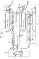
- Fig. 1 shows a multifunction machine tool to which is applied a tapping control system according to an embodiment of the present invention.
- This machine tool which operates in various working modes including tapping and deep-cut modes, comprises an AC digital spindle motor 1, for use as a principal-axis motor for tool rotation, and an AC servomotor 2 for tool feed.
- a tap 21 mounted on a tool holder 20 (Fig. 4) is rotated relative to a workpiece (not shown) by means of the digital spindle motor 1, and is driven in the working direction, with respect to the workpiece, by means of the feed motor 2.
- the spindle motor 1 is enabled to rotate at high speed so as to resist a substantial load at the time of deep cutting, e.g., milling.
- the tool holder 20 is replaceably fitted with a plurality of tools, such as the tap 21 and a milling cutter (not shown), by means of an automatic tool replacer.
- the holder 20 can also hold a tap 21 for rigid tapping in a nontelescopic manner.
- Numeral 3 denotes a numerical control unit including an interpolating circuit 3a, and symbol pC1 designates a pulse coder which produces a feedback pulse Fs with every rotation of the spindle motor 1 through a predetermined angle.
- Numeral 4 denotes position control means which delivers, as a speed command value, the difference between a distributed pulse Ps from the interpolating circuit 3a and the feedback pulse Fs from the pulse coder PC1.
- the means 4 includes an error register (not shown) and a D/A converter (not shown).
- Numerals 7 and 8 denote switching means which are shifted in response to a switching command CS from the numerical control unit 3. These means 7 and 8 are adapted to be shifted to a feedback control position, as shown in Fig.
- the switching means 7 applies the output of the position control means 4 to a digital control circuit 5, while the switching means 8 applies the feedback pulse Fs to the position control means 4.
- the means 7 and 8 are shifted to an open control position. In other words, the switching means 7 is shifted to apply a speed command SV for the spindle motor 1, delivered from the numerical control unit 3, to the digital control circuit 5, while the switching means 8 is shifted to prevent the feedback pulse Fs from being applied to the position control means 4.
- the digital control circuit 5 includes a speed control section 5a, current control section 5b, and a PWM (pulse width modulation) control section 5c.
- the speed control section 5a delivers a torque command in response to the difference between the speed command from the position control means 4 or the numerical control unit 3 and a present speed based on the feedback pulse Fs from the pulse coder PC1.
- the current control section 5b delivers a command current to each phase of the spindle motor 1 in accordance with a present driving current from current detectors 9 and 10.
- the PWM control section 5c modulates the pulse width of the command current output for each phase.
- the digital control circuit 5 delivers the modulation output thus obtained to a power circuit 6, thereby driving the same. In this manner, the spindle motor 1 is driven at a command speed.
- the digital control circuit 5 is of a conventional type (e.g., Japanese Patent Application No. 60-36051).
- Figs. 2 and 3 show motor follow-up performances for the cases in which the spindle motor is driven by means of the digital control circuit 5 and by the conventional system, individually.
- the spindle motor follows up the speed command with a considerable delay.
- the spindle motor controlled by the digital control circuit 5 can accurately follow up the speed command without any substantial delay.
- a servo-circuit 12 like the prior art one, detects the difference between a distributed pulse Pz from the interpolating circuit 3a and a feedback pulse Fz from the pulse coder PC2, by means of an error register in its position control section 12a.
- the output of this error register is converted into an analog signal by means of a D/A converter of the control section 12a, and is delivered as a speed command.
- the difference between this speed command and an actual speed from an F/V converter 12c is amplified by means of a speed control section 12b, and is delivered as a torque command.
- a driving current command for each phase is outputted in accordance with this torque command and an actual driving current value from current detectors 14 and 15 which are used to detect the driving current for the servomotor 2.
- a PWM control section 12e modulates the pulse width of the command. This modulation output is used to drive a power circuit 13, thereby driving the AC servomotor 2.
- Numerals 11 and 16 denote three-phase power sources, individually.
- tapping work is performed in a fixed cycle such that the tap 21 is first fed quickly to a working start point R, and the spindle motor 1 for tool rotation and the servomotor 2 for tool feed are then rotated forwardly, thereby effecting tapping for a predetermined distance d1 in a tapping direction (hereinafter referred to as Z-axis direction). Subsequently, the spindle motor 1 and the servomotor 2 are rotated reversely, so that the tap 21, while being rotated, is retreated or moved reversely to the work advancing direction, by a predetermined distance d2 (d1 > d2) shorter than the depth of finished work.
- the spindle motor 1 and the servomotor 2 are rotated forwardly, thereby effecting tapping again for the predetermined depth d1 (moved distance in the Z-axis direction is d1 + d2), in the same manner as aforesaid. Thereafter, the tap 21 is retreated again over the distance d2.
- the motors 1 and 2 are rotated reversely, so that the tool 4 is disengaged entirely from a tapping hole. Then, the tool is fed quickly to a position at a predetermined height, where it stands ready for the next working process.
- the tapping work is performed on the basis of the aforementioned fixed cycle. Referring now to Fig. 1, the tapping operation will be described.
- a tapping command is read from a working program by the numerical control unit 3
- a tapping tool is mounted on the tool holder by means of the automatic tool exchanger (not shown)
- the switching command CS is delivered from the numerical control unit 3.
- the switching means 7 and 8 are shifted to the feedback control position, and the speed commands Vs and Vz for the spindle motor 1 and the servomotor, which correspond to a pitch value designated by the working program, are applied to the interpolating circuit 3a.
- the distributed pulses Ps and Pz, interpolated linearly are delivered from the interpolating circuit 3a to the position control means 4 and the position control section 12a of the servo-circuit 12, respectively.
- the aforementioned pulse distribution by the interpolating circuit 3a is performed in a manner such that the servomotor 2 advances the tap 21 axially by a distance iP while the spindle motor 1 causes the tap 21 to make one revolution.
- the position control means 4 delivers, as the speed command, the difference between the distributed pulse Ps and the feedback pulse Fs from the pulse coder PC1, to the digital circuit 5.
- the digital circuit 5 executes speed control such that the spindle motor 1 is rotated forwardly at the command speed by means of the power circuit 6.
- the servo-circuit 12 also executes the aforesaid position control and speed control in accordance with the distributed pulse Pz and the feedback pulse Fz from the pulse coder PC2, so that the servomotor 2 is rotated forwardly by means of the power circuit 13.
- the spindle motor 1 and the servomotor 2 are rotated forwardly in synchronism with each other and at a required rotational speed ratio.
- the tap 21 is axially driven by the distance iP for each revolution thereof, thereby effecting the tapping work with the pitch provided by the working program.
- the speed commands Vs and Vz for the spindle motor 1 and the servomotor 2 are delivered in the opposite (or negative) direction.
- the interpolating circuit 3a delivers the distributed pulses Ps and Pz in the opposite direction through the same linear interpolation as aforesaid, thereby reversely rotating the spindle motor 1 and the servomotor 2 in synchronism with each other.
- This reverse operation is continued until the moved distance of the tap 21 attains d2.
- the tap 21 is rotated forwardly again, and is moved by (d1 + d2) in the Z-axis direction.
- the reverse direction is started in the same manner as aforesaid.
- the processes in the same fixed cycle are executed, and the workpiece is worked to the designated fixed depth position (Z-axis position).
- the spindle motor 1, used to rotate the tap 21, and the servomotor 2 are driven individually in accordance with the pulses distributed as a result of the linear interpolation in the interpolating circuit 3a. Accordingly, the spindle motor 1 and the servomotor 2 are synchronized, and the respective rotational positions of the motors 1 and 2, that is, the rotational position and the axial position of the tap 21, correspond entirely to each other. Even though the spindle motor 1 and the servomotor 2 are rotated in either direction, therefore, the aforesaid predetermined positional relationship can be maintained continually, thereby permitting accurate tapping work. Moreover, the tap 21 advances in the working direction for tapping while rotating forwardly, and then retreats by the fixed distance while rotating reversely. Thus, chips are eliminated, so that the tap 21 is subjected to less resistance, and can less frequently be broken.
- a deep cutting command e.g., a milling command
- a milling tool is mounted on the tool holder 20.
- the switching command CS is delivered from the numerical control unit 3, whereupon the switching means 7 and 8 are shifted to the open control position.
- the feedback pulse Fs from the pulse coder PC1 is stopped from being applied to the position control circuit 4, while the speed command Sv from the numerical control unit 3 is applied to the digital control circuit 5 through the switching means 7. Consequently, the spindle motor 1 starts to rotate at a speed corresponding to the speed command Sv, that is, at high speed, thus effecting deep cutting, such as milling.
Landscapes
- Engineering & Computer Science (AREA)
- Human Computer Interaction (AREA)
- Manufacturing & Machinery (AREA)
- Physics & Mathematics (AREA)
- General Physics & Mathematics (AREA)
- Automation & Control Theory (AREA)
- Mechanical Engineering (AREA)
- Numerical Control (AREA)
- Automatic Control Of Machine Tools (AREA)
Abstract
Claims (7)
- Un système de commande d'une opération de taraudage pour une machine capable d'effectuer une opération d'usinage sur une pièce d'ouvrage comprenant le taraudage d'une vis avec un taraud, et présentant un moteur de broche (1) pour la rotation d'une broche contrôlée par un circuit de commande de rotation (5), et un moteur d'alimentation (2) pour l'alimentation d'un outil contrôlée par un circuit de commande d'alimentation (12), le système comprenant :
des moyens d'instructions (3, 3a ; 4, 12a) pour fournir des instructions de vitesse au circuit de commande de rotation (5) et au circuit de commande d'alimentation (12) ; et
un détecteur (PC1) sensible à la rotation du moteur de broche (1) pour donner en sortie un signal de contre-réaction (Fs) indicateur d'une vitesse de rotation du moteur de broche ;
dans lequel ledit moteur de broche (1) et ledit moteur d'alimentation (2) sont entraînés en synchronisme l'un avec l'autre ;
caractérisé en ce que :
ledit moteur de broche (1) est un moteur de broche numérique, ledit circuit de commande de rotation (5) est un circuit de commande numérique, et ledit détecteur (PC1) est un codeur d'impulsions ;
ledit moteur d'alimentation (2) est un servomoteur et ledit circuit de commande d'alimentation (12) est un servocircuit ;
et en ce que lesdits moyens d'instructions (3, 3a, 4) comprennent :
un circuit d'interpolation (3a) pour répartir de manière individuelle des impulsions vers ledit circuit de commande numérique (5) et le circuit d'asservissement (12) pour effectuer une interpolation linéaire en accord avec une valeur de pas de l'opération de taraudage à effectuer ;
des moyens de commande de position (4) pour fournir une instruction de vitesse audit circuit de commande numérique (5) en accord avec les impulsions répartis provenant du circuit d'interpolation (3a) et le signal de contrôle de contre-réaction (Fs) sortant du codeur d'impulsions (PC1) pour effectuer une commande en contre-réaction de la position de rotation dudit moteur de broche (1) ;
et des moyens de commande d'inversion sous la forme d'une unité à commande numérique (3) qui contrôle ledit circuit d'interpolation (3a), lesdits moyens de commande de position (4) et le servocircuit (12) dans un mode de taraudage tel que ledit moteur de broche (1) et ledit servomoteur (2) sont chacun amenés à tourner vers l'avant pour effectuer une profondeur déterminée à l'avance d'opération de taraudage sur une pièce d'ouvrage, puis amener à tourner dans le sens inverse pour retirer le taraud d'une distance inférieure à ladite profondeur déterminée à l'avance, lesdites rotations vers l'avant et dans le sens inverse étant répétées de manière alternée jusqu'à l'achèvement de l'opération de taraudage sur ladite pièce d'ouvrage. - Un système de commande d'une opération de taraudage selon la revendication 1, dans lequel ledit moteur de broche (1) et ledit servomoteur (2) sont entrainés avec un rapport de vitesse de rotation déterminée à l'avance et correspondant à ladite valeur de pas.
- Un système de commande d'une opération de taraudage selon la revendication 1 ou 2, comprenant en outre des moyens de commutation (7, 8) pour commuter le système entre un mode de commande en contre-réaction et un mode de commande ouvert, ladite unité de commande numérique (3) pouvant être actionnée pour commuter lesdits moyens de commutation vers le mode de commande en contre-réaction pour effectuer l'opération de taraudage, et vers le mode de commande ouvert pour effectuer l'opération d'usinage profond.
- Un système de commande d'une opération de taraudage selon la revendication 3, dans lequel ladite unité de commande numérique (3) peut être actionnée pour faire tourner ledit moteur de broche (1) à une vitesse élevée pour un usinage profond lorsque le système est commuté vers le mode de commande ouvert.
- Un système de commande d'une opération de taraudage selon une revendication précédente quelconque, comprenant en outre un porte-outil (20) pour monter de manière non télescopique un outil tel qu'un taraud (21) ou un outil d'usinage profond.
- Un système de commande d'une opération de taraudage selon la revendication 3, monté de telle sorte que, lorsque lesdits moyens de commutation (7, 8) sont dans la position de commutation correspondant audit mode de commande ouvert, lesdites impulsions réparties et ledit signal de contre-réaction (Fs) sont empéchés d'être appliqués auxdits moyens de commande de position (4).
- Un système de commande d'une opération de taraudage selon une revendication précédente quelconque, dans lequel ledit circuit de commande numérique (5) comprend une section de commande de vitesse (5a) qui reçoit une instruction de vitesse provenant, soit des moyens de commande de position (4), soit directement de ladite unité de commande numérique (3), selon le mode choisi, une section de commande de courant (5b) couplée à ladite section de commande de vitesse (5a), et une section de commande de modulation par largeur d'impulsions (5c) pour fournir une instruction de couple au moteur de broche (1).
Applications Claiming Priority (4)
| Application Number | Priority Date | Filing Date | Title |
|---|---|---|---|
| JP64848/86 | 1986-03-25 | ||
| JP6484886A JPS62224520A (ja) | 1986-03-25 | 1986-03-25 | タツピング加工制御方式 |
| JP6484786A JPS62224519A (ja) | 1986-03-25 | 1986-03-25 | リジツトタツピング制御方式 |
| JP64847/86 | 1986-03-25 |
Publications (3)
| Publication Number | Publication Date |
|---|---|
| EP0267964A1 EP0267964A1 (fr) | 1988-05-25 |
| EP0267964A4 EP0267964A4 (fr) | 1990-04-10 |
| EP0267964B1 true EP0267964B1 (fr) | 1993-05-12 |
Family
ID=26405952
Family Applications (1)
| Application Number | Title | Priority Date | Filing Date |
|---|---|---|---|
| EP87902148A Expired - Lifetime EP0267964B1 (fr) | 1986-03-25 | 1987-03-25 | Systeme de commande d'une operation de taraudage |
Country Status (4)
| Country | Link |
|---|---|
| US (1) | US4985841A (fr) |
| EP (1) | EP0267964B1 (fr) |
| DE (1) | DE3785827T2 (fr) |
| WO (1) | WO1987005839A1 (fr) |
Families Citing this family (29)
| Publication number | Priority date | Publication date | Assignee | Title |
|---|---|---|---|---|
| JP2824648B2 (ja) * | 1988-08-02 | 1998-11-11 | ファナック株式会社 | 工作機械の主軸同期運転制御装置及びその方法 |
| JPH02256436A (ja) * | 1989-03-29 | 1990-10-17 | Okuma Mach Works Ltd | タッピング加工制御装置 |
| JPH0777691B2 (ja) * | 1989-04-28 | 1995-08-23 | オ−クマ株式会社 | 数値制御方法及びその装置 |
| JPH048423A (ja) * | 1990-04-26 | 1992-01-13 | Fanuc Ltd | タッピング方式 |
| US5193949A (en) * | 1991-02-22 | 1993-03-16 | Marantette William F | Arrangement for driving a rotary tool |
| US5165828A (en) * | 1991-08-12 | 1992-11-24 | Penn Engineering & Manufacturing Corp. | Cam-actuated thread tapper |
| JP2661422B2 (ja) * | 1991-08-16 | 1997-10-08 | 三菱電機株式会社 | 加工装置および加工方法 |
| JP3036143B2 (ja) * | 1991-09-02 | 2000-04-24 | 三菱電機株式会社 | 数値制御装置 |
| JP2866556B2 (ja) * | 1993-09-02 | 1999-03-08 | 三菱電機株式会社 | 工作機械の制御装置および制御方法 |
| DE4344817C2 (de) * | 1993-12-28 | 1995-11-16 | Hilti Ag | Verfahren und Einrichtung für handgeführte Werkzeugmaschinen zur Vermeidung von Unfällen durch Werkzeugblockieren |
| FR2720308B1 (fr) * | 1994-05-31 | 1996-08-09 | Recoules Fils Ets | Machine pneumatique d'usinage. |
| JP3595357B2 (ja) * | 1994-06-30 | 2004-12-02 | ファナック株式会社 | ディジタルサーボによるタンデム制御方法 |
| US5733198A (en) * | 1994-11-18 | 1998-03-31 | Brother Kogyo Kabushiki Kaisha | Thread cutting machine and thread cutting method |
| KR100335317B1 (ko) * | 1997-07-02 | 2002-05-06 | 다니구찌 이찌로오, 기타오카 다카시 | 서보모터의 동기제어장치 |
| JPH11245118A (ja) * | 1998-03-03 | 1999-09-14 | Brother Ind Ltd | ネジ加工制御装置 |
| DE19945395A1 (de) * | 1999-09-22 | 2001-04-05 | Deckel Maho Gmbh | Überwachungsverfahren und -einrichtung für numerisch gesteuerte Werkzeugmaschinen |
| DE60133956D1 (de) * | 2000-01-31 | 2008-06-26 | Yoshiaki Kakino | Gewindebohrgerät und Methode |
| US20050084345A1 (en) * | 2003-10-17 | 2005-04-21 | Frye Randy C. | Dual motor tapping machine |
| US7757384B2 (en) * | 2005-07-13 | 2010-07-20 | Macauley Andrew S | Apparatus for forming a hermetic seal about a cable extending from a waterproof pouch |
| GB2433454A (en) * | 2005-12-21 | 2007-06-27 | Hightown Engineering Ltd | Tap or reamer coupling |
| GB0625301D0 (en) * | 2006-12-19 | 2007-01-24 | Airbus Uk Ltd | Method and system for making holes in composite materials |
| DE102009054762A1 (de) * | 2009-12-16 | 2011-06-22 | Hilti Aktiengesellschaft | Steuerungsverfahren für eine handgeführte Werkzeugmaschine und Werkzeugmaschine |
| JP5325949B2 (ja) * | 2011-08-08 | 2013-10-23 | ファナック株式会社 | タッピング加工装置 |
| JP5314110B2 (ja) * | 2011-11-25 | 2013-10-16 | ファナック株式会社 | マスタ軸とスレーブ軸との同期制御を行うモータ制御装置 |
| US9513619B2 (en) * | 2012-06-05 | 2016-12-06 | Mitsubishi Electric Corporation | Numerical control device which performs tapping operation by using a main spindle and a feed shaft |
| JP5778801B2 (ja) * | 2014-01-23 | 2015-09-16 | ファナック株式会社 | 工作機械の数値制御装置 |
| DE102019124707B4 (de) * | 2019-09-13 | 2022-05-19 | EMUGE-Werk Richard Glimpel GmbH & Co. KG Fabrik für Präzisionswerkzeuge | Verfahren zum Erzeugen eines Gewindes mit Übersetzungseinheit |
| JP7396862B2 (ja) * | 2019-11-06 | 2023-12-12 | ファナック株式会社 | 工作機械の制御装置および工作機械の制御方法 |
| US12474692B2 (en) * | 2020-06-30 | 2025-11-18 | Fanuc Corporation | Control device and control method for machine tool |
Family Cites Families (8)
| Publication number | Priority date | Publication date | Assignee | Title |
|---|---|---|---|---|
| DE2259372B1 (de) * | 1972-12-04 | 1974-04-11 | Index-Werke Kg Hahn & Tessky, 7300 Esslingen | Numerisch gesteuerte Drehmaschine mit einer Einrichtung zum Einstellen der Hauptspindel um vorbestimmte Winkel |
| US3854353A (en) * | 1973-06-20 | 1974-12-17 | Bendix Corp | Method and apparatus for performing a threading operation on a rotating workpiece |
| US4079235A (en) * | 1976-12-27 | 1978-03-14 | Mcdonnell Douglas Corporation | Computer numerically controlled threadcutting machine tool |
| JPS5633249A (en) * | 1979-08-24 | 1981-04-03 | Fanuc Ltd | Synchronous operation control system for electric motor |
| JPS60155319A (ja) * | 1984-01-24 | 1985-08-15 | Brother Ind Ltd | ねじ加工装置 |
| JPS60167731A (ja) * | 1984-02-03 | 1985-08-31 | Fanuc Ltd | タツピング加工方法 |
| GB2164878B (en) * | 1984-08-27 | 1987-10-21 | Brother Ind Ltd | A machine tool for machining a workpiece by feeding a cutting tool in a series of discrete steps and related method |
| JPH0757444B2 (ja) * | 1985-06-28 | 1995-06-21 | ブラザー工業株式会社 | ねじ加工装置 |
-
1987
- 1987-03-25 WO PCT/JP1987/000182 patent/WO1987005839A1/fr not_active Ceased
- 1987-03-25 DE DE8787902148T patent/DE3785827T2/de not_active Expired - Lifetime
- 1987-03-25 EP EP87902148A patent/EP0267964B1/fr not_active Expired - Lifetime
- 1987-03-25 US US07/138,842 patent/US4985841A/en not_active Expired - Lifetime
Also Published As
| Publication number | Publication date |
|---|---|
| WO1987005839A1 (fr) | 1987-10-08 |
| EP0267964A4 (fr) | 1990-04-10 |
| EP0267964A1 (fr) | 1988-05-25 |
| DE3785827D1 (de) | 1993-06-17 |
| DE3785827T2 (de) | 1993-08-19 |
| US4985841A (en) | 1991-01-15 |
Similar Documents
| Publication | Publication Date | Title |
|---|---|---|
| EP0267964B1 (fr) | Systeme de commande d'une operation de taraudage | |
| US4879660A (en) | Thread cutting machine with synchronized feed and rotation motors | |
| EP0025652B1 (fr) | Système de commande pour synchroniser les moteurs d'une machine-outil pour des opérations de filetage | |
| EP0051477B1 (fr) | Procédé et appareil de commande d'orientation de broche | |
| JP3369346B2 (ja) | 停電時制御装置 | |
| JP2661422B2 (ja) | 加工装置および加工方法 | |
| US3418549A (en) | Combined numerical and torque control for a work and feed machine tool | |
| EP0557530A1 (fr) | Dispositif de commande numerique | |
| EP0331749B1 (fr) | Commande de synchronisation d'un moteur de mandrin et d'un moteur d'avance | |
| EP0374259A4 (en) | Two opposed main shaft type cnc lathe | |
| EP0034927B1 (fr) | Appareil de commande d'orientation de broche | |
| US6111382A (en) | Device for controlling tapping device provided with composite tool having boring and tapping sections | |
| EP0088133B1 (fr) | Mecanisme de changement automatique d'outils | |
| EP0364593B1 (fr) | Machine-outil pourvue de deux broches principales | |
| JP2700819B2 (ja) | タッピング方法 | |
| JPS62224520A (ja) | タツピング加工制御方式 | |
| JPH0343012B2 (fr) | ||
| JPH11165241A (ja) | 旋盤におけるワーク加工方法 | |
| JP2553384B2 (ja) | 複合工作機械の周速一定同期制御方法とその装置 | |
| US20020025758A1 (en) | Tool path preparing method and machining method | |
| JPS62228345A (ja) | 交流モ−タの制御回路 | |
| JP3729084B2 (ja) | 多軸同期制御装置および多軸同期制御方法 | |
| JPH0751992A (ja) | 穴開け加工方式 | |
| JPS6334018A (ja) | タツプ加工制御装置 | |
| EP0078855A1 (fr) | Dispositif de commande numerique |
Legal Events
| Date | Code | Title | Description |
|---|---|---|---|
| PUAI | Public reference made under article 153(3) epc to a published international application that has entered the european phase |
Free format text: ORIGINAL CODE: 0009012 |
|
| 17P | Request for examination filed |
Effective date: 19871203 |
|
| AK | Designated contracting states |
Kind code of ref document: A1 Designated state(s): DE FR GB |
|
| A4 | Supplementary search report drawn up and despatched |
Effective date: 19900410 |
|
| 17Q | First examination report despatched |
Effective date: 19911212 |
|
| GRAA | (expected) grant |
Free format text: ORIGINAL CODE: 0009210 |
|
| AK | Designated contracting states |
Kind code of ref document: B1 Designated state(s): DE |
|
| REF | Corresponds to: |
Ref document number: 3785827 Country of ref document: DE Date of ref document: 19930617 |
|
| EN | Fr: translation not filed | ||
| REG | Reference to a national code |
Ref country code: DE Ref legal event code: 8320 Ref document number: 3785827 Country of ref document: DE |
|
| PGFP | Annual fee paid to national office [announced via postgrant information from national office to epo] |
Ref country code: DE Payment date: 20060309 Year of fee payment: 20 |
|
| PLBE | No opposition filed within time limit |
Free format text: ORIGINAL CODE: 0009261 |
|
| STAA | Information on the status of an ep patent application or granted ep patent |
Free format text: STATUS: NO OPPOSITION FILED WITHIN TIME LIMIT |