EP0268005A2 - Amortisseur rotatif d'oscillation - Google Patents
Amortisseur rotatif d'oscillation Download PDFInfo
- Publication number
- EP0268005A2 EP0268005A2 EP87104055A EP87104055A EP0268005A2 EP 0268005 A2 EP0268005 A2 EP 0268005A2 EP 87104055 A EP87104055 A EP 87104055A EP 87104055 A EP87104055 A EP 87104055A EP 0268005 A2 EP0268005 A2 EP 0268005A2
- Authority
- EP
- European Patent Office
- Prior art keywords
- vibration damper
- torsional vibration
- wall parts
- chambers
- damper according
- Prior art date
- Legal status (The legal status is an assumption and is not a legal conclusion. Google has not performed a legal analysis and makes no representation as to the accuracy of the status listed.)
- Withdrawn
Links
Images

Classifications
-
- F—MECHANICAL ENGINEERING; LIGHTING; HEATING; WEAPONS; BLASTING
- F16—ENGINEERING ELEMENTS AND UNITS; GENERAL MEASURES FOR PRODUCING AND MAINTAINING EFFECTIVE FUNCTIONING OF MACHINES OR INSTALLATIONS; THERMAL INSULATION IN GENERAL
- F16F—SPRINGS; SHOCK-ABSORBERS; MEANS FOR DAMPING VIBRATION
- F16F15/00—Suppression of vibrations in systems; Means or arrangements for avoiding or reducing out-of-balance forces, e.g. due to motion
- F16F15/10—Suppression of vibrations in rotating systems by making use of members moving with the system
- F16F15/16—Suppression of vibrations in rotating systems by making use of members moving with the system using a fluid or pasty material
- F16F15/161—Suppression of vibrations in rotating systems by making use of members moving with the system using a fluid or pasty material characterised by the fluid damping devices, e.g. passages, orifices
Definitions
- the invention relates to a torsional vibration damper according to the preamble of claim 1.
- Such a torsional vibration damper is known from DE-A 31 20 407.
- the machine parts delimiting the partial chambers are designed to be unyielding in a partial area, which means that a damping effect of constant quality always results with a relative rotation of the two rings. This is unsatisfactory with regard to the isolation of high-frequency vibrations.
- the invention has for its object to develop a torsional vibration damper of the type mentioned in such a way that there is a good damping effect with respect to torsional vibrations of a large amplitude and good insulation with respect to torsional vibrations of a small amplitude.
- a torsional vibration damper of the type mentioned in that the subchambers are delimited in at least one partial area by flexible wall parts.
- the subchambers are able to absorb the changes in volume resulting from small relative rotations without pressure, so that in these cases there is no pressing of liquid through the connection opening.
- Corresponding torsional vibrations are therefore excellently isolated in the torsional vibration damper according to the invention.
- the volume compliance; e can be specifically designed to be amplitude-dependent, so that damping and hardening can be coordinated as a function of the relative amplitude.
- the torsional vibration damper according to the invention is characterized by a constant, excellent operating behavior over long periods of time. Its properties can also be modified, if necessary, by filling only part of the available segment chambers with liquid or by using a liquid with a different viscosity in part of the segment chambers.
- the flexible wall parts of the partial chambers can consist of thin-walled membranes made of plastomeric or elastomeric materials. In this case, they have a particularly good flexibility, which allows the largely unpressurized volume absorption when torsional vibrations of small amplitude are introduced.
- the use of thin-walled, rigid plates, which are held by ring membranes from the surrounding wall parts, is also possible.
- the resilient wall parts can be provided between the subchambers and the outside air, which makes it easier to control the function.
- an arrangement in the partition wall separating two associated subchambers is also possible. It is recommended in applications in which the torsional vibration damper is exposed to a greater mechanical load from the outside.
- the size of the torsional amplitude of the torsional vibration damper according to the invention, at which the damping effect begins, can be determined very precisely if the play of the movable wall parts is limited by stops. Appropriate training is particularly recommended in cases in which high-frequency interference vibrations that require insulation occur in addition to low-frequency vibrations that require damping.
- the resilient wall parts can also be resiliently suspended in order to obtain a gradual transition from the damping-free to the damped operating state of the torsional vibration damper.
- the use of attacks can be superfluous, despite similar effectiveness. This eliminates the problem of stop noises that sometimes occur when using stops.
- the resilient wall parts can be formed in one piece with the sealing elements which seal the rings from one another and / or from the partition, which simplifies production.
- a one-piece design with rubber-elastic spring bodies is also possible, which, after the previous relative rotation, bring the rings back into a neutral, mutually associated position.
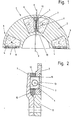
- the torsional vibration damper shown in Figures 1 and 2 consists of the drive ring 1 and the driven ring .
- the output ring 2 has an annular recess on the end face, which is closed in a liquid-tight manner by a crimped end cover 13.
- the end cover 13 forms an integral part of the output ring 2 in the operational state.
- the segment chambers 3 enclosed by the driven ring 2, the spring body 12 and the drive ring 1 are filled with a mixture of glycol and water and contain dividing walls 4 which extend in the radial direction and are fixed non-rotatably on the drive ring 1 and by a circumferential sealing lip 10 relative to that Spring body 12, the driven ring 2 and the end cover 13 are movably sealed.
- the partitions 4 essentially have a radial extension.
- the partitions a contain a resilient wall part in the form of a thin, stiff leaflet which can be moved back and forth between stops 9 between the partial chambers 5, 6 of the segment chambers.
- the size and the play of this resilient wall part are dimensioned such that there is no change in pressure in the partial chambers 5, 6 in the case of torsional vibrations of a small torsional amplitude in the drive flange 1. In this case, therefore, no liquid is pressed through the connection opening 7 between the subchambers 5, 6 and no damping effect is achieved.
- Corresponding Vernierschwin- supply e n therefore is iso- in excellent dimensions and are not noticeable in the output ring.
- the flexible wall part 8 When torsional vibrations of a greater amplitude are introduced, the flexible wall part 8 alternately comes to rest on the left and the right of the two stops located in front of it, which is followed by the pressing of liquid through the opening 7 into the partial chamber 5 or 6 of lower pressure. This results in a good damping effect with regard to torsional vibrations of this type.
- the guide ring 11 serves to ensure a rotationally symmetrical assignment of the output ring 2 to the drive ring 1. Its use is particularly recommended for small dimensions of the torsional vibration damper when no other centering means are available.
- the drawn version can also be used without it.
- the partition 4 is integrally formed with the drive ring 1 and the resilient wall part of the subchamber 6 is arranged between the same and the outside air.
- the execution can be produced particularly inexpensively. It can be used as a vibration damper due to the inertia mass 9 connected to the driven ring 2, whereby the effectiveness in this regard can be increased by a design in which the parts above the driven ring 2 are present instead of the same in a mirror-image arrangement and by a circulating belt with the Parts are connected.
- Mutual assignment in such a way that each of the subchambers 5, 6 is delimited in one wall area by a flexible wall part 8 is possible and advantageous.
- the corresponding wall parts prevent the occurrence of an increase in pressure in the subchambers 5,6 when torsional vibrations of small amplitude are introduced, as a result of which corresponding vibrations are well insulated.
- torsional vibrations of a large amplitude when torsional vibrations of a large amplitude are introduced, liquid is pressed through the connecting opening 7 to achieve a throttling effect in the space of lower pressure. Corresponding torsional vibrations are thereby damped.
Landscapes
- Engineering & Computer Science (AREA)
- General Engineering & Computer Science (AREA)
- Physics & Mathematics (AREA)
- Acoustics & Sound (AREA)
- Aviation & Aerospace Engineering (AREA)
- Mechanical Engineering (AREA)
- Combined Devices Of Dampers And Springs (AREA)
- Mechanical Operated Clutches (AREA)
- Surgical Instruments (AREA)
- Buildings Adapted To Withstand Abnormal External Influences (AREA)
Applications Claiming Priority (2)
| Application Number | Priority Date | Filing Date | Title |
|---|---|---|---|
| DE19863639190 DE3639190A1 (de) | 1986-11-15 | 1986-11-15 | Drehschwingungsdaempfer |
| DE3639190 | 1986-11-15 |
Publications (2)
| Publication Number | Publication Date |
|---|---|
| EP0268005A2 true EP0268005A2 (fr) | 1988-05-25 |
| EP0268005A3 EP0268005A3 (en) | 1989-07-05 |
Family
ID=6314102
Family Applications (1)
| Application Number | Title | Priority Date | Filing Date |
|---|---|---|---|
| EP87104055A Withdrawn EP0268005A3 (en) | 1986-11-15 | 1987-03-19 | Rotational oscillation damper |
Country Status (4)
| Country | Link |
|---|---|
| US (1) | US4873887A (fr) |
| EP (1) | EP0268005A3 (fr) |
| JP (2) | JPS63130947A (fr) |
| DE (1) | DE3639190A1 (fr) |
Cited By (3)
| Publication number | Priority date | Publication date | Assignee | Title |
|---|---|---|---|---|
| EP0403831A1 (fr) * | 1989-06-22 | 1990-12-27 | Eaton Corporation | Amortisseur à palette pour convertisseur de couple |
| GB2261716A (en) * | 1991-11-23 | 1993-05-26 | Holset Engineering Co | Torsional vibration damper |
| FR3057324A1 (fr) * | 2016-10-07 | 2018-04-13 | Peugeot Citroen Automobiles Sa | Double volant moteur comportant des membranes elastiques fermees |
Families Citing this family (15)
| Publication number | Priority date | Publication date | Assignee | Title |
|---|---|---|---|---|
| JPH01168036U (fr) * | 1988-05-18 | 1989-11-27 | ||
| JPH0357541U (fr) * | 1989-07-31 | 1991-06-03 | ||
| US5724862A (en) * | 1992-05-21 | 1998-03-10 | Eti Technologies Inc. | Dynamic balancing method and apparatus |
| JPH07110050A (ja) * | 1993-10-13 | 1995-04-25 | Daikin Mfg Co Ltd | 捩じり振動減衰装置 |
| US5931051A (en) * | 1996-02-16 | 1999-08-03 | Ott; Vern D. | Vibration dampener for a rotating shaft |
| JP2001500949A (ja) * | 1996-07-16 | 2001-01-23 | シンプスン インターナショナル(ユーケイ)リミテッド | 捩り振動ダンパ |
| DE19705873B4 (de) * | 1997-02-15 | 2006-06-08 | Stromag Ag | Elastische Wellenkupplung |
| US5935007A (en) * | 1997-05-29 | 1999-08-10 | Meritor Heavy Vehicle Systems, Llc | Torsional vibration damper |
| US6327732B1 (en) * | 2000-05-10 | 2001-12-11 | Maytag Corporation | Fluid balancing ring and method for using same |
| DE10056661C2 (de) * | 2000-11-15 | 2003-04-10 | Freudenberg Carl Kg | Dämpfungseinrichtung für eine drehelastische Kupplung |
| DE10057822C2 (de) * | 2000-11-21 | 2003-04-10 | Freudenberg Carl Kg | Dämpfungseinrichtung für eine drehelastische Kupplung |
| DE102005027834A1 (de) * | 2005-06-16 | 2006-12-28 | Man Nutzfahrzeuge Ag | Drehschwingungsdämpfer |
| US9664251B2 (en) * | 2015-01-09 | 2017-05-30 | Deere & Company | Coupler for translating rotational forces |
| US20190011013A1 (en) * | 2017-07-07 | 2019-01-10 | GM Global Technology Operations LLC | Active vibration damper for a vehicle driveline component |
| US12345309B1 (en) * | 2024-03-25 | 2025-07-01 | Ante Puljic | Gravitational torque amplifier apparatus and method |
Family Cites Families (22)
| Publication number | Priority date | Publication date | Assignee | Title |
|---|---|---|---|---|
| US1970369A (en) * | 1930-06-10 | 1934-08-14 | Nevin S Focht | Hydraulic shock absorber |
| US1893625A (en) * | 1930-11-15 | 1933-01-10 | Mechanical Dev Company | Shock absorber |
| US2181415A (en) * | 1935-12-14 | 1939-11-28 | Donald E Willard | Valve mechanism for shock absorbers |
| NL162999C (nl) * | 1971-06-30 | 1980-07-15 | Stichting Reactor Centrum | Trillingsdemper met een hermetisch gesloten vat gevuld met een dempfluidum, alsmede werkwijze voor het vervaardigen van een membraamring bij de trillingsdemper. |
| US3992963A (en) * | 1975-01-21 | 1976-11-23 | Wallace-Murray Corporation | Elastomer and liquid torsional vibration damper |
| DE2714230A1 (de) * | 1977-03-30 | 1978-10-05 | Hasse & Wrede Gmbh | Drehschwingungsdaempfer mit viskosem daempfungsmedium |
| US4339963A (en) * | 1978-10-27 | 1982-07-20 | Wallace Murray Corporation | Viscous damper |
| US4200004A (en) * | 1979-03-15 | 1980-04-29 | Wallace Murray Corporation | Zero slip torsional vibration damper |
| DE3020993A1 (de) * | 1980-06-03 | 1981-12-10 | Carl Hasse & Wrede Gmbh, 1000 Berlin | Drehschwingungsdaempfer mit viskosem daempfungsmedium |
| DE3049109A1 (de) * | 1980-12-24 | 1982-07-08 | Thyssen Industrie Ag, 4300 Essen | Drehelastische stoss- und schwingungsdaempfende kupplung mit einem scheibenartigen kupplungskoerper |
| DE3142024C1 (de) * | 1981-10-23 | 1983-04-14 | Boge Gmbh, 5208 Eitorf | Drehelastische,hydraulisch daempfende Kupplung |
| DE3215765A1 (de) * | 1982-04-28 | 1983-05-19 | Daimler-Benz Ag, 7000 Stuttgart | Drehschwingungsdaempfer fuer wellen, insbesondere antriebswellen fuer brennkraftmaschinen |
| JPS5934081A (ja) * | 1982-08-19 | 1984-02-24 | Taiheiyo Kogyo Kk | 比例制御弁の制御回路 |
| JPS5934895A (ja) * | 1982-08-23 | 1984-02-25 | Microbial Chem Res Found | プルマイシン製造法 |
| US4583723A (en) * | 1983-06-10 | 1986-04-22 | Toyoda Gosei Co., Ltd. | Elastically damping device for suspension of engine |
| DE3334630C1 (de) * | 1983-09-24 | 1984-11-15 | Fa. Carl Freudenberg, 6940 Weinheim | Verfahren zur Herstellung einer Federkupplung |
| DE3334881A1 (de) * | 1983-09-27 | 1985-04-11 | Fa. Carl Freudenberg, 6940 Weinheim | Gummikupplung |
| DE3340253A1 (de) * | 1983-11-08 | 1985-05-15 | Brown, Boveri & Cie Ag, 6800 Mannheim | Baugruppensteckeinheit |
| JPS60227016A (ja) * | 1984-04-23 | 1985-11-12 | Nissan Motor Co Ltd | たわみ継手 |
| DE3420570C1 (de) * | 1984-06-01 | 1989-12-14 | SGF Süddeutsche Gelenkscheibenfabrik GmbH & Co KG, 8264 Waldkraiburg | Drehschwingungstilger |
| DE3423222A1 (de) * | 1984-06-21 | 1984-12-06 | Klaus Prof. Dr.-Ing. 1000 Berlin Federn | Viskoelastisch gedaempfter drehschwingungstilger mit federgekoppeltem schwungring |
| DE3545401A1 (de) * | 1985-12-19 | 1987-07-02 | Federn Klaus | Gedaempfter drehschwingungstilger |
-
1986
- 1986-11-15 DE DE19863639190 patent/DE3639190A1/de active Granted
-
1987
- 1987-03-19 EP EP87104055A patent/EP0268005A3/de not_active Withdrawn
- 1987-09-07 JP JP62223821A patent/JPS63130947A/ja active Pending
- 1987-11-05 US US07/117,792 patent/US4873887A/en not_active Expired - Fee Related
-
1991
- 1991-02-04 JP JP1991003614U patent/JPH0712752Y2/ja not_active Expired - Lifetime
Cited By (4)
| Publication number | Priority date | Publication date | Assignee | Title |
|---|---|---|---|---|
| EP0403831A1 (fr) * | 1989-06-22 | 1990-12-27 | Eaton Corporation | Amortisseur à palette pour convertisseur de couple |
| GB2261716A (en) * | 1991-11-23 | 1993-05-26 | Holset Engineering Co | Torsional vibration damper |
| GB2261716B (en) * | 1991-11-23 | 1995-05-10 | Holset Engineering Co | A torsional vibration damper |
| FR3057324A1 (fr) * | 2016-10-07 | 2018-04-13 | Peugeot Citroen Automobiles Sa | Double volant moteur comportant des membranes elastiques fermees |
Also Published As
| Publication number | Publication date |
|---|---|
| JPH0712752Y2 (ja) | 1995-03-29 |
| JPS63130947A (ja) | 1988-06-03 |
| DE3639190C2 (fr) | 1989-08-31 |
| EP0268005A3 (en) | 1989-07-05 |
| JPH0488746U (fr) | 1992-07-31 |
| DE3639190A1 (de) | 1988-05-26 |
| US4873887A (en) | 1989-10-17 |
Similar Documents
| Publication | Publication Date | Title |
|---|---|---|
| EP0268005A2 (fr) | Amortisseur rotatif d'oscillation | |
| EP0044545B2 (fr) | Support de moteur à deux chambres d'amortissement hydraulique | |
| DE3528175C2 (fr) | ||
| EP0154828B1 (fr) | Support élastique à amortissement hydraulique, en particulier pour le moteur de propulsion dans des véhicules automoteurs | |
| DE2802896C2 (de) | Gummilager mit hydraulischer Dämpfung | |
| DE3721444A1 (de) | Huelsenfeder mit einer fluessigkeitsfuellung | |
| DE102004059406A1 (de) | Mit einem Fluid gefüllte Schwingungsdämpfungsvorrichtung | |
| DE112009002210T5 (de) | Schwingungsabsorber mit eingeschlossener Flüssigkeit | |
| DE68909208T2 (de) | Abgedichtete, mit flüssigkeit gefüllte lagervorrichtung. | |
| EP0335005B1 (fr) | Support en caoutchouc à amortissement hydraulique | |
| DE3440054C2 (fr) | ||
| DE3617813C2 (fr) | ||
| EP0415001B1 (fr) | Support hydraulique | |
| DE4123892C2 (de) | Elastische Lagerung | |
| DE3828132C2 (de) | Elastische Aufhängung mit einer Flüssigkeitsfüllung | |
| DE69713222T2 (de) | Fluidenthaltende, schwingungsisolierende Vorrichtung | |
| DE3829021A1 (de) | Elastische aufhaengung mit einer fluessigkeitsfuellung | |
| DE3587349T2 (de) | Schwingungsdaempfungsvorrichtung. | |
| DE4009275A1 (de) | Zylindrisches, elastisches verbindungselement mit einer fluidfuellung | |
| DE3909234C1 (fr) | ||
| DE3312529A1 (de) | Stossdaempfer | |
| DE1775432B2 (de) | Drehschwingungsdaempfer | |
| DE3638647A1 (de) | Schwingungsdaempfer | |
| DE3736162A1 (de) | Huelsengummifeder | |
| EP0248943A2 (fr) | Support à double chambre pour moteur |
Legal Events
| Date | Code | Title | Description |
|---|---|---|---|
| PUAI | Public reference made under article 153(3) epc to a published international application that has entered the european phase |
Free format text: ORIGINAL CODE: 0009012 |
|
| AK | Designated contracting states |
Kind code of ref document: A2 Designated state(s): DE FR GB IT |
|
| PUAL | Search report despatched |
Free format text: ORIGINAL CODE: 0009013 |
|
| AK | Designated contracting states |
Kind code of ref document: A3 Designated state(s): DE FR GB IT |
|
| 17P | Request for examination filed |
Effective date: 19890605 |
|
| 17Q | First examination report despatched |
Effective date: 19900731 |
|
| STAA | Information on the status of an ep patent application or granted ep patent |
Free format text: STATUS: THE APPLICATION HAS BEEN WITHDRAWN |
|
| 18W | Application withdrawn |
Withdrawal date: 19901203 |
|
| R18W | Application withdrawn (corrected) |
Effective date: 19901203 |
|
| RIN1 | Information on inventor provided before grant (corrected) |
Inventor name: ULLRICH, GUENTER Inventor name: DOERGE, UDO Inventor name: ANDRAE, RAINER HORST, DR. Inventor name: KURR, KLAUS, DR. |