EP0268013A2 - Pompe avec moteur électrique à rotor noyé ou avec accouplement magnétique - Google Patents
Pompe avec moteur électrique à rotor noyé ou avec accouplement magnétique Download PDFInfo
- Publication number
- EP0268013A2 EP0268013A2 EP87108088A EP87108088A EP0268013A2 EP 0268013 A2 EP0268013 A2 EP 0268013A2 EP 87108088 A EP87108088 A EP 87108088A EP 87108088 A EP87108088 A EP 87108088A EP 0268013 A2 EP0268013 A2 EP 0268013A2
- Authority
- EP
- European Patent Office
- Prior art keywords
- pump
- wall
- canned
- pump according
- pot
- Prior art date
- Legal status (The legal status is an assumption and is not a legal conclusion. Google has not performed a legal analysis and makes no representation as to the accuracy of the status listed.)
- Granted
Links
Images


Classifications
-
- H—ELECTRICITY
- H02—GENERATION; CONVERSION OR DISTRIBUTION OF ELECTRIC POWER
- H02K—DYNAMO-ELECTRIC MACHINES
- H02K49/00—Dynamo-electric clutches; Dynamo-electric brakes
- H02K49/10—Dynamo-electric clutches; Dynamo-electric brakes of the permanent-magnet type
- H02K49/104—Magnetic couplings consisting of only two coaxial rotary elements, i.e. the driving element and the driven element
- H02K49/106—Magnetic couplings consisting of only two coaxial rotary elements, i.e. the driving element and the driven element with a radial air gap
-
- F—MECHANICAL ENGINEERING; LIGHTING; HEATING; WEAPONS; BLASTING
- F04—POSITIVE - DISPLACEMENT MACHINES FOR LIQUIDS; PUMPS FOR LIQUIDS OR ELASTIC FLUIDS
- F04D—NON-POSITIVE-DISPLACEMENT PUMPS
- F04D13/00—Pumping installations or systems
- F04D13/02—Units comprising pumps and their driving means
- F04D13/021—Units comprising pumps and their driving means containing a coupling
- F04D13/024—Units comprising pumps and their driving means containing a coupling a magnetic coupling
- F04D13/025—Details of the can separating the pump and drive area
-
- F—MECHANICAL ENGINEERING; LIGHTING; HEATING; WEAPONS; BLASTING
- F04—POSITIVE - DISPLACEMENT MACHINES FOR LIQUIDS; PUMPS FOR LIQUIDS OR ELASTIC FLUIDS
- F04D—NON-POSITIVE-DISPLACEMENT PUMPS
- F04D13/00—Pumping installations or systems
- F04D13/02—Units comprising pumps and their driving means
- F04D13/06—Units comprising pumps and their driving means the pump being electrically driven
- F04D13/0606—Canned motor pumps
- F04D13/0626—Details of the can
-
- F—MECHANICAL ENGINEERING; LIGHTING; HEATING; WEAPONS; BLASTING
- F04—POSITIVE - DISPLACEMENT MACHINES FOR LIQUIDS; PUMPS FOR LIQUIDS OR ELASTIC FLUIDS
- F04D—NON-POSITIVE-DISPLACEMENT PUMPS
- F04D15/00—Control, e.g. regulation, of pumps, pumping installations or systems
- F04D15/0077—Safety measures
-
- F—MECHANICAL ENGINEERING; LIGHTING; HEATING; WEAPONS; BLASTING
- F04—POSITIVE - DISPLACEMENT MACHINES FOR LIQUIDS; PUMPS FOR LIQUIDS OR ELASTIC FLUIDS
- F04D—NON-POSITIVE-DISPLACEMENT PUMPS
- F04D15/00—Control, e.g. regulation, of pumps, pumping installations or systems
- F04D15/02—Stopping of pumps, or operating valves, on occurrence of unwanted conditions
- F04D15/0245—Stopping of pumps, or operating valves, on occurrence of unwanted conditions responsive to a condition of the pump
- F04D15/0263—Stopping of pumps, or operating valves, on occurrence of unwanted conditions responsive to a condition of the pump the condition being temperature, ingress of humidity or leakage
-
- H—ELECTRICITY
- H02—GENERATION; CONVERSION OR DISTRIBUTION OF ELECTRIC POWER
- H02K—DYNAMO-ELECTRIC MACHINES
- H02K49/00—Dynamo-electric clutches; Dynamo-electric brakes
- H02K49/10—Dynamo-electric clutches; Dynamo-electric brakes of the permanent-magnet type
- H02K49/104—Magnetic couplings consisting of only two coaxial rotary elements, i.e. the driving element and the driven element
-
- H—ELECTRICITY
- H02—GENERATION; CONVERSION OR DISTRIBUTION OF ELECTRIC POWER
- H02K—DYNAMO-ELECTRIC MACHINES
- H02K5/00—Casings; Enclosures; Supports
- H02K5/04—Casings or enclosures characterised by the shape, form or construction thereof
- H02K5/12—Casings or enclosures characterised by the shape, form or construction thereof specially adapted for operating in liquid or gas
- H02K5/128—Casings or enclosures characterised by the shape, form or construction thereof specially adapted for operating in liquid or gas using air-gap sleeves or air-gap discs
-
- H—ELECTRICITY
- H02—GENERATION; CONVERSION OR DISTRIBUTION OF ELECTRIC POWER
- H02K—DYNAMO-ELECTRIC MACHINES
- H02K11/00—Structural association of dynamo-electric machines with electric components or with devices for shielding, monitoring or protection
Definitions
- the invention relates to a pump with a canned motor or canned magnet drive with an outer drive part and an inner rotary part magnetically coupled therewith, the outer drive and inner rotary part being hermetically separated from one another by means of a can.
- Pumps of this type are known, e.g. B. by DBGM 82 08046. With the help of its can, its outer drive part is hermetically sealed from the pump area containing the pumped medium. Such pumps are therefore particularly suitable for pumping aggressive or otherwise dangerous media, which must be shielded from the environment or the drive area of the pump. Such proven in practice
- a pump in accordance with the aforementioned DBGM already provides emergency seals and shutdown elements which shut down the pump in the event of an accident.
- this only provides short-term protection, as these breakdown seals usually.
- d Usually consist of dynamic seals and only offer incomplete protection.
- the can is at least double-walled.
- the hermetic tightness of the pump is maintained in the event of damage to a canned wall, so that with double walls practically double protection, with multiple there is a corresponding multiple protection.
- a correspondingly damaged pump can thus be put out of operation and repaired without part of the pumped medium getting into the environment.
- a particularly advantageous embodiment of the invention consists in that the wall interior enclosed by the tube walls has a medium or a device by means of which wall leaks can be displayed on the outside of the device.
- the double or multiple walls complement one another and the display medium or a display device in their safety functions. If one of the canned walls is damaged, the hermetic seal of the pump is maintained, while at the same time this damage is indicated on the outside of the device, so that such a damaged but still hermetically sealed pump can be taken out of operation at an early stage and repaired if necessary. This means that a damage warning signal or a signal to shut down the pump can be given very early. A pump that is shut down in this way remains hermetically sealed until repair, practically for any length of time.
- the tube walls are in a tight Distance so that the wall interior delimited by the two opposite tube wall surfaces is just gas-permeable.
- Gas can then be used as the display medium for the accident, which preferably has a pressure which is at least slightly above the ambient pressure.
- the gas can still penetrate the entire interior of the wall; accordingly, if a can wall is damaged due to its overpressure compared to the ambient pressure, it can undergo a pressure drop which indicates the damage.
- the closely spaced tube walls of the canned tube keep the transmission losses between the outer drive part and the magnetically coupled inner rotating part small.
- the criteria of minimizing magnetic transmission losses on the one hand and the immediate, simple indication of damage are optimized.
- the close, contact-close distance between the two opposite pipe wall surfaces has the additional advantage that good heat transfer from the outer pipe wall to the inner pipe wall and thus to the pumped medium of the pump is possible.
- the inner tube wall of the canned tube is acted upon by the conveying medium, often by a flowing partial stream branched off from the main delivery stream of the pump, so that the aforementioned heat transfer to the inner tube wall has the advantage that heat generated due to eddy current is better transported away in the outer tube wall can.
- the interior of the wall expediently has at least one pressure connection for introducing the measuring medium and / or for pressure measurement.
- One can as mentioned, z. B. accommodate a gas whose pressure is at least slightly above the ambient pressure. If practically normal atmospheric pressure then prevails outside the can, a pressure drop in the gas initially introduced within the wall interior with a slightly excessive pressure indicates a leak in the can outer wall. An increase in pressure with this gas, on the other hand, indicates damage to the inner wall of the canned pipe, provided that - as is usually the case - the pumped liquid is under higher pressure than the gas in the inner wall.
- the at least double-walled design of the canned tube according to the invention is possible both in pumps with canned motor drive and in pumps with canned magnet drive.
- the can is generally closed off on the drive side by a base, and the can and base are then usually referred to as can cans.
- it is advantageous in the case of canned magnetic pumps designed with canned pot if the bottom of the canned pot (short: "canned pot bottom") is at least partially double-walled and a pot bottom area enclosed by a pot bottom plate and a pot bottom outer wall is connected to the wall interior of the associated canned pipe, preferably gas-permeable connected is. Due to such a comprehensive double or multiple walling of the entire canned pot, such damages can now also be indicated which originate from the pot bottom of the canned pot.
- the pot base plate is located in the immediate vicinity of a flange of the rotating drive part.
- Impurities e.g. B.
- grinding contact with the rotating drive part leads in the long run to grinding through the now provided outer wall of the pot base and thus to an indication of the pressure loss that occurs. Measured pressure fluctuations can thus provide information about possible damage to a canned wall and / or damage in the area of the bottom of the canned pot.
- a liquid measuring medium can also have advantages which far outweigh the aforementioned disadvantages.
- the delivery liquid can be used as the measurement medium use yourself, if necessary a medium that is sufficiently neutral to this.
- Another advantageous option for displaying damage to the canned or pot bottom walls is that at least one signal film is provided between these walls for the device-side display of mechanical damage and contact with the medium to be conveyed.
- a film practically fulfills the same safety function, like her before standing for a gas under pressure in the interior of the wall has been described in more detail.
- the use of a gas as the measuring medium has the advantage that the pump is easy to manufacture
- the use of a signal foil has the advantage that the tube walls can lie on top of one another while the foil is being clamped, thereby increasing the stability of the can.
- the signal film is designed to be thermally conductive, the eddy current-induced heat of the can outer wall can be passed on well to the inner wall of the can and thus into the conveying medium adjacent to it.
- FIG. 1 The basic structure of a canned magnetic pump S can be seen from FIG. 1.
- a connection housing 1 there is a drive shaft 2 and an outer drive part 3 connected to it.
- This encloses an inner rotary part 4 in a pot-like manner and concentrically.
- This is connected to a pump wheel 5.
- Drive part 3 and inner rotating part 4 are magnetically coupled via magnets 6, so that a rotational movement of the driving part 3 is transmitted via magnetic coupling forces to the inner rotating part 4, which drives the pump wheel 5.
- a canned pot 7, which is tightly attached to the pump housing P on the pump side.
- This canned pot 7 forms a hermetic seal of the outer pump drive with respect to the pump interior 70 and the conveying medium 8, which flows through the inner part of the canned pot 7 in the direction of arrows Pf 1 for cooling and lubricating the inner rotating part 4 in a known manner in a secondary flow.
- the can 9 of the can pot 7 is now double-walled.
- the tube walls 14 u. 21 enclosed wall interior 10 filled with a medium 11 or there is also a device described in more detail below, by means of which wall leaks can be displayed on the outside of the device.
- the tube walls 14 u. 21 are concentric to the axis of rotation 20 of the inner rotating part 4 and the pumps wheel 5 arranged. They have the same wall thickness W of approximately 0.5 mm and are at a very small distance d from one another (FIG. 5), which is dimensioned such that it is just just permeable to gas or liquid.
- gas In the wall interior 10 there is gas as the measuring medium, which is indicated in the area of a connecting flange 19 by points 11.
- a pressure measuring instrument 37 is connected to the pressure connection 15. If necessary. it may be advantageous to attach further pressure instruments 37 at other locations in the wall interior, e.g. B. to obtain more precise information about the pressure profile within the canned pot 7.
- the pressure connection 15 runs through a connecting flange 19 which connects the tube walls 14 u. 21 encloses on the pump side and connects the canned pot 7 to the pump housing P.
- the canned pot 7 encloses an opening 16 in the outer tubular wall 21 of the canned pot 7, through which the gas or another measuring or display medium 11 can enter the wall interior 10.
- the canned pot bottom is composed of the pot bottom plate 13 and the pot bottom outer wall 34 and thereby encloses the pot bottom interior area 33. This is connected to the wall interior 10 of the tube area 9.
- the two walls 14 and 21 of the canned pot 7 are welded separately to the pot base plate 13 and the pot base outer wall 34.
- the outer wall 34 of the pot bottom is designed to be rigid so that the weld 42 is not excessively stressed by the lever forces occurring during the bending.
- FIG. 2 shows, as a further, modified exemplary embodiment of the invention, a canned motor pump, designated as a whole by M, which has an electrical external drive area 51 and a central tube area 52. Both parts are hermetically sealed from one another by a can 50.
- a working shaft 53 is arranged in the tube area 52 and carries a motor rotor 54. This is applied in a known manner via an alternating electrical field generated by a stator 55 and a winding head 56 driven.
- corresponding pump impeller is flowed through for cooling and lubrication of the bearings in the usual manner from a branched partial flow of the medium in the direction of arrows Pf 1.
- the can 50 hermetically seals the external drive region 51, in particular the stator 55 and the winding head 56, from the rotor region 52 and the branched partial flow of the conveying medium located therein.
- damage or destruction of the single-walled canned pipe 50 mostly leads to destruction of the winding head 56 and possibly the stator 55.
- the can 50 is also double-walled with the help of tube walls 60 and 61.
- the display medium can be connected between the outer and inner walls 60 u. 61 arranged signal foil to be replaced.
- This can e.g. B. consist of a very thin electrical network, which, embedded in a thin tissue, reacts to mechanical interruptions or when wetted by liquids with changes in resistance (see. Fig. 15).
- Filling the wall interior 10 or 62 of the canned pot 7 of the canned pipe 50 with a gas also has the following particular advantages: it speaks about the temperature changes which cannot be avoided when starting up the pump-motor or pump-clutch unit and starting the delivery process, especially on its usually expected temperature increases, not as strongly as z. B. a liquid. This will make one Pressure measurement, which indicates the good or bad condition of the canned pot 7 or the canned 50, facilitates.
- suitable indicators e.g. B. moisture indicators, analyzers, gas detectors or the like. Indicators come into question, the determination and display of the good or bad condition via pressure indicator 37, namely gas-actuated pressure indicator, is a preferred embodiment.
- an automatic switch-off 38 for the drive motor of the pump and / or a warning lamp 39 can be provided in a known manner.
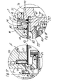
- FIG. 5 shows an embodiment of the canned pot 7 'of a canned magnet pump that is somewhat modified compared to FIG. 4.
- the outer wall 34 'of the bottom of the pot is annular and the bottom 13' of the bottom of the pot is formed with a greater thickness in its central area.
- the inner tube wall 14 is tightly connected by means of a weld 40 to a conventional welding lip located at the edge of the pot bottom wall 13 '.
- the annular pot bottom outer wall 34 ' has an inner and an outer welding lip. The latter is tightly connected to the outer tube wall 21 via the weld seam 42, while the weld seam 41 connects two adjacent weld lips from the annular outer wall 34 'and the bottom plate 13'.
- the outer wall 34 'of the pot base is particularly rigid and simple to manufacture, and the entire canned pot 7' formed in this way, in particular its sweat stitched 40, 41 u. 42 particularly susceptible to faults.
- FIG. 1 shows a centrifugal pump with a canned magnetic coupling drive according to the invention with a centrifugal pump impeller 5
- FIG. 6 shows a liquid ring gas pump F with a canned magnetic coupling drive.
- the general structure of such known liquid ring gas pumps is e.g. B. known from DE patent 29 12 938.
- the associated paddle wheel which is moved in the direction of rotation by the inner rotating part 4, is designated by 5 '.
- the remaining designations correspond to those of FIG. 1 and the associated description.
- Liquid ring gas pumps F are not infrequently used for the conveyance of highly toxic gases and / or are operated with toxic operating liquid. Their interaction with an at least double-walled canned magnetic coupling drive is accordingly an advantageous application example of the invention. Another area of application is that of positive displacement pumps.
- the canned tube can be of multi-wall design, a double-walled design, as described with reference to the exemplary embodiments, is generally the most advantageous design because the gap between the outer drive and the inner rotating part 3, 4 can be kept relatively small, so that the efficiency of the magnetic coupling is not particularly affected.
- a suitable choice of material for the can 9 or 50, z. B. when using high nickel alloys with a ferrite content of less than 0.5%, the efficiency of the magnetic coupling only needs to drop by a few percent. Then the reduction in performance is of the order of magnitude that is still included in the power reserves of such couplings.
- the distance between the tube walls 14 u. 21 is the better overview because of enlarged figures in particular. The same applies to the distance d between the tube walls 60 and 61 z. B. and 3 and 4 u. 5.
- stator 55 and the associated winding head 56 form an outer drive part 3 'which, for. B. corresponds to the outer drive part 3 in the canned magnetic coupling according to FIG. 1.
- FIG. 7 in connection with Figures 8, 9, 10 u. 10 a essentially shows the motor part of a canned motor pump M ', in which the inner pipe wall 60' can be easily replaced.
- this inner tube wall 60 ' has on its side facing the pump a radially outwardly extending sealing flange 71, while at its end remote from the pump it has a radially inwardly extending sealing flange 72 (cf. in particular FIG. 10).
- 7 shows the bearing 64 on the pump side and the bearing 65 remote from the pump of the working shaft 53 of the canned motor pump M '.
- the pump-remote bearing 65 is held in a known manner in a pump-remote bearing block 73, which in turn is inserted with a centering piece 63 a in a corresponding centering hole 63 b of a pump-remote end cover 74, these parts 73, 74 via bearing block connecting screws 75 firmly and tightly are interconnected.
- FIG. 9 shows well how the sealing flange 72 remote from the pump of the inner tube wall 60 'of the can 50 between the distant bearing bracket 73 and the end cap 74 remote from the pump is clamped.
- the essentially radially oriented pump-distant sealing flange 72 is connected to the end of the inner tube wall 60 'remote from the pump via an annular weld seam (cf.
- the pump-side sealing flange 71 is also essentially radially oriented, but, in order to create enough space for weld seams 69, 76 to be described later, it can have an annular bulge 79 directed in the direction of the pump part (indicated on the left there) (see FIG. 8 and Fig. 7, upper half).
- the pump-side sealing flange 71 can, however, as can be clearly seen from FIG.
- Corresponding sealing washers can be arranged, for example, on the sealing flange 72 remote from the pump and in a known manner on corresponding sealing surfaces of the canned motor pump M or M '; they are not shown here.
- end cap 74 remote from the pump the bearing bracket 73 remote from the pump and the stator housing with the end flanges 82, 83 including casing tube 81, motor stator 55 and outer tube wall 61
- casing tube 81, motor stator 55 and outer tube wall 61 Remove inner tube wall 60 ', for example after damage, comparatively easily and replace it with a corresponding spare part. No sweat is required seams turned off or to be welded again during assembly. This is particularly important in applications where such welds are subject to high quality requirements, which is often the case. This also applies to the use of canned motor pumps M in companies or geographical areas where appropriately qualified welding work cannot be carried out.
- FIG. 7 to 9 and 10 a also shows the formation and attachment of the outer tube wall 61 of the can 50.
- the outer tube wall 61 As can be seen particularly well from FIG. 10 a, as seen in the longitudinal section of the outer tube wall 61, it is essentially U-shaped; the outer tube wall 61 forms the U-web, while the sealing flanges 67 u. 68 form the U-legs.
- the essentially radially oriented sealing flanges 67 u. 68 are angled at their inner edge in a known manner to weld lips 57 and 58 and the parts 67, 68 and 61 are connected to one another there via corresponding annular weld seams 76, similar to what was described in more detail above for the inner tube wall 60 '.
- the wall thickness W of the tube walls 14 u. 21 or 60 u. 61 can be different or the same, depending on the attachment to a pump S with canned magnetic coupling drive or a pump M with canned motor drive; Furthermore, the area of application of the corresponding pumps S or M can play a role in the selection of the wall thicknesses of the tube walls 14, 21 or 60 u. 61 play. In the case of a canned motor pump M according to FIGS. 2, 3 or 7, one will regularly ensure that the wall thickness W of the outer pipe wall 61 withstands the delivery pressure in the pump M if the inner pipe wall 60 or 60 'has suffered damage. Under normal operating conditions. B. with a wall thickness of 0.5 mm.
- the outer tube wall 61 is not as separate replacement part of canned motor pumps M or M 'is formed, since it is hardly endangered in such canned motor pumps. If necessary, it can be replaced with the entire motor stator, which in particular comprises parts 55, 56 and 81 to 83.
- FIG. 11 shows a pump S 'which is somewhat modified compared to FIG. 1 and has a canned magnetic coupling drive with inner slide bearings 24 and 25, in which the drive shaft 26 is supported.
- This connects the inner rotating part 4 of the magnetic coupling in a rotationally fixed manner to a pump impeller similar to that from FIG. 1.
- the magnets are located analogously to FIG 6.
- the drive shaft 26 has a central shaft bore 27 through which, in a known manner, a branched-off partial flow corresponding to the arrows Pf 2 through the gap denoted overall by 9 pipe is guided.
- FIGS. 11 and 12 This is now double-walled according to the invention with an inner tube wall 14 and an outer tube wall 21, as has already been explained in more detail in the embodiment according to FIG. 1.
- the embodiment according to FIGS. 11 and 12 is characterized in that the inner tube wall 14 can be removed together with the pot base plate 13 tightly attached to it, without this being the case, for. B. a weld seam needs to be destroyed. Accordingly, the inner tube wall 14, which together with its pot bottom plate 13 forms a separate inner canned pot 28, if necessary, e.g. B. if damaged, can be replaced without complicated measures against a new inner canned pot.
- the pump-side end 29 of the inner tube wall 14 is provided with a fastening flange 30 which is tightly but releasably fastened in a corresponding recess 31 of the connecting flange 19 'by means of screws 32. 11, which is shown enlarged in FIG. 12, one can still clearly see that the pot bottom plate 13 of the inner canned pot 28 is completely separated from the pot bottom outer wall 34, similar to the embodiment according to FIG.
- the inner tube wall 14 is connected to the fastening flange 30 at its pump-side end 29 in the manner already described by means of an annular weld seam 22.
- FIG. 13 A pump S '' which is somewhat modified compared to the pump S 'shown with canned magnetic coupling drive in FIG. 11 is shown in FIG. 13. It can be seen particularly clearly that both the inner tube wall 14 and the outer tube wall 21 of the double-walled canned pot 7 are detachably attached to the connecting flange 19 'by means of a fastening flange 30 or 30'. If there is corresponding damage, the inner tube wall 14 or the outer tube wall 21 can be selected or if necessary, both tube walls 14, 21 can be easily replaced. In this case, the pot base plate 13 and the pot base outer wall 34, as can be clearly seen in FIG. 11 and in particular FIG. 12, are each designed separately and connected to the corresponding tube wall 14 and 21, respectively.
- FIG. 14 shows an auxiliary bearing 17 for a shaft end 18 attached to the inner rotating part 4, which is connected to the pot bottom plate 13, which in this case is of correspondingly thick and stable design.
- a double-walled canned pot 7 ' is shown on an enlarged scale, the inner tube wall 60' of which is connected to a fastening flange 30 via a weld seam 22 and has a separate pot base plate 13 at the pump end, on which there is an auxiliary bearing 17 is located.
- the outer tube wall 61 of the canned pot 7 ' is connected to the connecting flange 19' via a weld seam 22 '; it has a separate outer wall 34 of the bottom of the pot at its end remote from the pump.
- FIG. 15 modified from FIG. 14 a section of a canned pot 7 "modified compared to FIG. 14 is shown in partial longitudinal section.
- the two tube walls 60 'and 61 can be removed together, similar to the embodiment according to FIG. B.
- the wall thicknesses W will be increased accordingly. So that the gap between the outer drive part 3 or 3 'on the one hand and the inner rotary part 4 or the Mctorrotor 54 and thus the magnetic losses do not become too large, only the outer tube wall 21 or 61 in its wall thickness W can be on the a must be designed for the strength values specified by the operating pressure of the pump. For example, at high operating pressure of the pump, W a can be approximately 7 mm, while Wi remains in the order of 0.3 to 0.5 mm. If the inner tube wall 14 of a pump S with canned magnetic coupling drive is then destroyed, the outer tube wall 21 still secures the hermetic seal of the pump S.
- the comparatively thin inner tube wall 14 can become somewhat elastic deforming to the essentially still as a stable jacket, only at one point damaged outer tube wall 21 and support there, for example, while a display medium 11 or a corresponding device indicates the leakage of the outer tube wall 21 and z. B. stops the pump S.
- the can 9 or 50 can not only be double-walled, but can also be multi-walled if there is a corresponding need for safety.
- the inner tube wall 60 is in the section below left by adding another inner tube wall 60 a for itself double-walled again.
- a display medium 11 a or a corresponding device can also be provided in the space 88 between these two inner tube walls 60 u. 60 a. Both the medium 11 a and this device can be connected to a measuring instrument 37 a.
- FIG. 15 schematically shows how the interior 10 between the inner tube wall 14 or 60 'on the one hand and the outer tube wall 21 or 61 on the other hand is provided with a signal film 12 shown there in cross hatching. It is connected via an electrical line 89 to a measuring instrument 37b and can report damage to the inner tube wall 14 or 60 and / or the outer tube wall 21 or 61 in the manner already described or in the manner already mentioned via such Stop the pump S or M or let a warning lamp 39 light up.
- this pumped liquid or this auxiliary liquid can optionally also be used as the measuring medium 11 in the interior 10 or 62 as the measuring medium 11 accommodate.
- FIGS. 16 to 18 An embodiment of the canned motor pump M ′′ is shown in FIGS. 16 to 18.
- the motor rotor 54 and the associated motor stator 55 are omitted there.
- the inner pipe wall 60 'with a pump-side sealing flange 71 via a weld seam 69 and the outer pipe wall 61 via a weld seam 76 with an outer sealing flange 88 are sealed.
- the pump-side sealing flange 71 and the outer Sealing flanges 88 each abut the flat sides of a holding flange 43.
- All three parts 71, 43 and 88 are sealingly clamped between the pump housing P and the pump-side end flange 83 of the motor housing 81 to 83. According to the advantageous development of the invention, they have the welded seams 69 and 76 opposite ends of the tube walls 60 'and 61, however, no welded-on flanges corresponding to the sealing flanges 71 and 88. Rather, a special sealing flange 46, approximately circular in side view, is provided on the end of the motor part of the canned motor pump M''remote from the pump the sealing flange 46 has two bevels 89 and 90 on (Fig. 16 u. 18).
- end flange 74 or with the bearing flange 82 each have an annular space 47 and 48, each receiving a sealing ring 45 and 44.
- the seal ring 44 near the pump seals the outer tube wall 61 and the seal ring 45 remote from the pump seals the inner tube wall 60 '.
- Such a design has the particular advantage that if a pipe wall 60 'or 61 is damaged, it can be replaced together with the respective sealing flange 88 or 71 as an unwelded component against an undamaged new component without destroying a weld seam or with one the necessary precision and tightness must be made again.
- sealing flanges 71 and 88 at the pump-side ends of the tube walls 60 u. 61 and the aforementioned sealing rings 44 and 45 are attached to the pump distal ends of the sealing flange 46 there.
- a reverse arrangement of the sealing flanges 71 and 88 welded tightly and tightly to the tube walls 60 and 61 at the ends of these tube walls 60, 61 remote from the pump would, however, also be possible in principle.
- a gas possibly one with a vacuum relative to the ambient pressure, can be accommodated. If the canned motor pump M or M 'or M' 'works with overpressure, the following display options for a pressure gauge 37 result in a simple manner: If the pressure display rises little, this indicates damage to the outer pipe wall 51, the pressure display increases sharply, this indicates damage to the inner tube wall 60.
- the measuring device 37 can also indicate in the latter case whether the inner tube wall 14 or 60 or the outer tube wall 21 or 61 has been damaged.
- the double-walled structure of the canned pot 7 and the canned pipe 50 not only brings the safety of a thicker canned pipe but also, in conjunction with the display option, the advantages of timely warning or switching off of the pump S with canned magnetic coupling drive or the canned motor pump M.
- the simple repair remains , also in the event of an accident. 16 to 18 also has the advantage over the embodiment according to FIG.
Landscapes
- Engineering & Computer Science (AREA)
- Mechanical Engineering (AREA)
- General Engineering & Computer Science (AREA)
- Power Engineering (AREA)
- Structures Of Non-Positive Displacement Pumps (AREA)
- Measuring Fluid Pressure (AREA)
Priority Applications (3)
| Application Number | Priority Date | Filing Date | Title |
|---|---|---|---|
| AT87108088T ATE68038T1 (de) | 1986-11-20 | 1987-06-04 | Pumpe mit spaltrohr. |
| DE8787110038T DE3780125D1 (de) | 1986-11-20 | 1987-07-11 | Pumpe mit spaltrohrmotor- oder spaltrohrmagnetkupplungsantrieb. |
| AT87110038T ATE77872T1 (de) | 1986-11-20 | 1987-07-11 | Pumpe mit spaltrohrmotor- oder spaltrohrmagnetkupplungsantrieb. |
Applications Claiming Priority (2)
| Application Number | Priority Date | Filing Date | Title |
|---|---|---|---|
| DE3639720 | 1986-11-20 | ||
| DE3639720A DE3639720C1 (de) | 1986-11-20 | 1986-11-20 | Pumpe mit Spaltrohrmotor- oder Spaltrohrmagnetkupplungsantrieb |
Publications (4)
| Publication Number | Publication Date |
|---|---|
| EP0268013A2 true EP0268013A2 (fr) | 1988-05-25 |
| EP0268013A3 EP0268013A3 (en) | 1989-03-29 |
| EP0268013B1 EP0268013B1 (fr) | 1991-10-02 |
| EP0268013B2 EP0268013B2 (fr) | 1997-01-02 |
Family
ID=6314414
Family Applications (1)
| Application Number | Title | Priority Date | Filing Date |
|---|---|---|---|
| EP87108088A Expired - Lifetime EP0268013B2 (fr) | 1986-11-20 | 1987-06-04 | Pompe avec moteur électrique à rotor noyé ou avec accouplement magnétique |
Country Status (5)
| Country | Link |
|---|---|
| US (1) | US4838763A (fr) |
| EP (1) | EP0268013B2 (fr) |
| JP (1) | JPS63140888A (fr) |
| AT (1) | ATE68038T1 (fr) |
| DE (5) | DE3645260C2 (fr) |
Cited By (10)
| Publication number | Priority date | Publication date | Assignee | Title |
|---|---|---|---|---|
| EP0279220A3 (fr) * | 1987-02-14 | 1989-03-22 | Richter Chemie-Technik GmbH | Dispositif de détection des fuites pour pompe centrifuge magnétique |
| EP1158175A3 (fr) * | 2000-05-20 | 2005-04-27 | WILO GmbH | Moteur à manchon d'entrefer en feuille |
| EP1777414A1 (fr) * | 2005-10-21 | 2007-04-25 | Klaus Union GmbH & Co. KG | Pompe à entraînement magnétique |
| WO2019234170A1 (fr) * | 2018-06-07 | 2019-12-12 | Klaus Union Gmbh & Co. Kg | Pompe à un couplage magnétique pourvue d'une chemise d'entrefer double enveloppe |
| US12331781B2 (en) | 2023-02-03 | 2025-06-17 | General Electric Company | Dual thrust bearing systems and methods for operating the same |
| US12345279B2 (en) | 2022-05-03 | 2025-07-01 | General Electric Company | Oil lubricated fluid pumps with oil separators |
| US12421968B2 (en) | 2022-05-03 | 2025-09-23 | General Electric Company | Axial flux motor driven pump systems for pressurizing fluid in closed loop systems |
| US12448978B2 (en) | 2022-05-03 | 2025-10-21 | General Electric Company | Layered barrier cans for pumps and methods of producing the same |
| US12460647B2 (en) | 2022-05-03 | 2025-11-04 | General Electric Company | Integrated bearing systems for dynamically supporting shafts in pump systems |
| US12601352B2 (en) | 2022-05-03 | 2026-04-14 | General Electric Company | High pressure magnetic coupling shrouds and methods of producing the same |
Families Citing this family (37)
| Publication number | Priority date | Publication date | Assignee | Title |
|---|---|---|---|---|
| US4934902A (en) * | 1984-09-27 | 1990-06-19 | Myron Mantell | Failure sensing device for a diaphragm pump |
| DE3645260C2 (de) * | 1986-11-20 | 1995-01-19 | Hermetic Pumpen Gmbh | Pumpe mit einem Spaltrohrmagnetkupplungsantrieb |
| DE3712459A1 (de) * | 1987-04-11 | 1988-10-27 | Klaus Union Armaturen | Magnetischer pumpenantrieb |
| US4971523A (en) * | 1988-09-13 | 1990-11-20 | Nordson Corporation | Dual diaphragm apparatus with diaphragm assembly and rupture detection methods |
| DE3931665C1 (en) * | 1989-09-22 | 1991-02-21 | Wilo-Werk Gmbh & Co Pumpen- Und Apparatebau, 4600 Dortmund, De | Split-ring electric motor for pump - has feeder coupled to pump chamber at point exhibiting high pressure |
| US5253986A (en) * | 1992-05-12 | 1993-10-19 | Milton Roy Company | Impeller-type pump system |
| US5248245A (en) * | 1992-11-02 | 1993-09-28 | Ingersoll-Dresser Pump Company | Magnetically coupled centrifugal pump with improved casting and lubrication |
| DE4303629A1 (de) * | 1993-02-09 | 1994-08-18 | Junkalor Gmbh | Übertemperatur- und Anlaufsicherung in Pumpen mit Permanentmagnet-Kupplungen |
| DE19581602T1 (de) * | 1994-03-29 | 1997-04-17 | Orbital Eng Australia | Zweiteilige Pumpe |
| DE4411367A1 (de) * | 1994-03-31 | 1995-10-05 | Burgmann Dichtungswerk Feodor | Spalttopfgedichtete magnetische Antriebseinrichtung |
| US5616973A (en) * | 1994-06-29 | 1997-04-01 | Yeomans Chicago Corporation | Pump motor housing with improved cooling means |
| DE4446915A1 (de) * | 1994-12-28 | 1996-07-04 | Wilo Gmbh | Magnetischer Pumpenantrieb |
| US5505594A (en) * | 1995-04-12 | 1996-04-09 | Sheehan; Kevin | Pump with co-axial magnetic coupling |
| DE29716109U1 (de) * | 1997-09-08 | 1999-01-14 | Speck Pumpenfabrik Walter Spec | Spalttopfpumpe |
| US6183208B1 (en) * | 1997-10-03 | 2001-02-06 | Roper Holdings, Inc. | Immersible motor system |
| US6123093A (en) * | 1998-04-30 | 2000-09-26 | D'antonio Consultants International, Inc. | System for controlling fluid flow |
| AT407660B (de) * | 1998-11-04 | 2001-05-25 | Hoerbiger Hydraulik | Hydraulisches kombiaggregat |
| US6196813B1 (en) * | 1999-07-06 | 2001-03-06 | Flowserve Management Company | Pump assembly including integrated adapter |
| JP4780859B2 (ja) * | 2000-12-18 | 2011-09-28 | 日機装株式会社 | キャンドモータポンプ |
| US6722854B2 (en) | 2001-01-24 | 2004-04-20 | Sundyne Corporation | Canned pump with ultrasonic bubble detector |
| US6783322B2 (en) | 2002-04-23 | 2004-08-31 | Roper Holdings, Inc. | Pump system with variable-pressure seal |
| US6997688B1 (en) | 2003-03-06 | 2006-02-14 | Innovative Mag-Drive, Llc | Secondary containment for a magnetic-drive centrifugal pump |
| US7265468B1 (en) * | 2005-11-22 | 2007-09-04 | Mancl Dennis J | Water repellent motor sleeve |
| GB2471908B (en) * | 2009-07-17 | 2011-11-16 | Hmd Seal Less Pumps Ltd | Non-intrusive vapour detector for magnetic drive pump |
| EP2489880B1 (fr) * | 2010-09-27 | 2020-10-07 | Nikkiso Co., Ltd. | Connecteur etanche a la pression et antideflagrant |
| CH705235A1 (de) * | 2011-07-15 | 2013-01-15 | Cp Pumpen Ag | Magnetgekoppelte Kreiselpumpe mit Spalttopfüberwachung. |
| KR101220393B1 (ko) * | 2011-09-20 | 2013-01-09 | 기아자동차주식회사 | 유레아 에스씨알 시스템용 펌프 구조 |
| DE102011119625A1 (de) * | 2011-11-29 | 2013-05-29 | Wilo Se | Nassläufer-Motorpumpe |
| DE102011119626A1 (de) * | 2011-11-29 | 2013-05-29 | Wilo Se | Nassläufer-Motorpumpe |
| KR101250969B1 (ko) * | 2012-02-20 | 2013-04-05 | 캄텍주식회사 | 차량용 워터펌프 |
| CN102865975B (zh) * | 2012-09-13 | 2015-06-17 | 杭州沃镭科技有限公司 | 双工位离合器助力器密封在线检测台 |
| US20150226220A1 (en) * | 2014-02-13 | 2015-08-13 | Pentair Flow Technologies, Llc | Pump and Electric Insulating Oil for Use Therein |
| US10156240B2 (en) | 2016-06-16 | 2018-12-18 | Scott C. Mancl | Motor-driven fan with trapped adhesive for minimizing vibration |
| WO2021050870A1 (fr) * | 2019-09-13 | 2021-03-18 | Upwing Energy, LLC | Système d'entraînement magnétique à écoulement traversant pour élévation artificielle |
| US11603845B2 (en) * | 2021-02-11 | 2023-03-14 | Zi Yi Electrical Engineering Co., Ltd. | Magnetic drive pump |
| DE102021207416B3 (de) * | 2021-07-13 | 2022-11-10 | Siemens Aktiengesellschaft | Spaltrohr für eine elektrische rotierende Maschine, Herstellungsverfahren dazu |
| US12506380B2 (en) | 2023-06-24 | 2025-12-23 | Scott C. Mancl | Bearing seal for motors |
Family Cites Families (42)
| Publication number | Priority date | Publication date | Assignee | Title |
|---|---|---|---|---|
| DE7638C (de) * | Gebrüder JUNGHANS in Schramberg, (Württemberg) | Kalenderwerk | ||
| FR864365A (fr) * | 1940-03-26 | 1941-04-25 | Perfectionnement aux compresseurs à membrane | |
| US2662478A (en) * | 1950-01-31 | 1953-12-15 | Surre Francois Eugene | Diaphragm pump and compressor |
| FR1033425A (fr) * | 1950-03-08 | 1953-07-10 | Pumpenbau Brugg K Ru Tschi | Pompe de circulation pour chauffage central |
| GB748708A (en) * | 1953-06-15 | 1956-05-09 | James Russell Smith | Improvements in electric driving means |
| DE943739C (de) * | 1953-10-28 | 1956-06-01 | Josef Emmerich | Membrane fuer Pumpen, Ventile oder Schaltgeraete sowie Verfahren zum Betrieb derartiger Vorrichtungen |
| US3163790A (en) * | 1961-11-10 | 1964-12-29 | Fostoria Corp | Motor driven pumps |
| US3131638A (en) * | 1962-07-05 | 1964-05-05 | Lapp Insulator Company Inc | Leak detecting device |
| DE1226740B (de) * | 1963-07-25 | 1966-10-13 | Hofer Andreas | Anzeigevorrichtung fuer den Membranbruch an Membranverdichtern |
| FR1552305A (fr) * | 1967-12-15 | 1969-01-03 | ||
| DE1926000A1 (de) * | 1968-05-21 | 1969-11-27 | Girling Ltd | Abdichtender Trennkolben |
| DE1907677C2 (de) * | 1969-02-15 | 1983-03-24 | Hermetic-Pumpen Gmbh, 7803 Gundelfingen | Spaltrohrmotor, vorzugsweise zum Antrieb einer Hochdruckpumpe |
| DE1956632A1 (de) * | 1969-11-11 | 1971-05-19 | Veredlung Gmbh Guss & Stahl | Spaltrohrmotor-Kreiselpumpenaggregat |
| CH516795A (de) | 1969-11-26 | 1971-12-15 | Froelich Martin | Verfahren zur Dichtigkeitsprüfung einer Dichtungsstelle |
| DE2014047A1 (de) * | 1970-03-24 | 1971-10-07 | Blum A | Elektrische Tauchpumpe |
| US3661060A (en) * | 1970-08-05 | 1972-05-09 | Duriron Co | Diaphragms for high pressure compressors and pumps |
| GB1496035A (en) * | 1974-07-18 | 1977-12-21 | Iwaki Co Ltd | Magnetically driven centrifugal pump |
| DE2534740C3 (de) * | 1975-08-04 | 1983-02-03 | Franz 4630 Bochum Klaus | Spaltrohrkreiselpumpe |
| FR2389784B1 (fr) * | 1977-05-06 | 1984-02-24 | Siebec Filtres | |
| SU684679A2 (ru) * | 1978-01-20 | 1979-09-05 | Fedorov Viktor F | Защитна гильза статора |
| DE2912938C2 (de) * | 1979-03-31 | 1985-03-14 | Lederle Gmbh Pumpen Und Maschinenfabrik, 7800 Freiburg | Flüssigkeitsring-Gaspumpe |
| JPS58147627A (ja) | 1982-02-26 | 1983-09-02 | Hitachi Ltd | 流体漏れ検出素子 |
| DE3207436A1 (de) * | 1982-02-27 | 1983-09-08 | Franz Klaus Union Armaturen, Pumpen Gmbh & Co, 4630 Bochum | Geraet und aggregat zur erwaermung eines stroemenden mediums |
| DE8208046U1 (de) * | 1982-03-20 | 1982-07-08 | Lederle GmbH Pumpen- und Maschinenfabrik, 7803 Gundelfingen | Kreiselpumpenaggregat mit Spaltrohrmagnetkupplung |
| FR2533636B1 (fr) * | 1982-09-28 | 1987-03-20 | Milton Roy Dosapro | Dispositif de detection de rupture de membrane |
| DE3243617A1 (de) * | 1982-11-25 | 1984-05-30 | Hermetic-Pumpen Gmbh, 7803 Gundelfingen | Pumpe zum foerdern hochkorrosiver medien |
| GB2145882A (en) * | 1983-07-21 | 1985-04-03 | Teikoku Denki Seisakusho Kk | Partition structure for a dynamo-electric machine |
| DE3337086C2 (de) * | 1983-10-12 | 1993-12-23 | Hermann Kraemer | Kreiselpumpe mit Spaltrohr-Magnetkupplungsantrieb |
| DE3413930A1 (de) * | 1984-04-13 | 1985-10-31 | Friedrichsfeld Gmbh, Steinzeug- Und Kunststoffwerke, 6800 Mannheim | Kreiselpumpe |
| US4569634A (en) * | 1984-09-27 | 1986-02-11 | Mantell Myron E | Failure sensing diaphragm for a diaphragm pump |
| JPS6219748A (ja) | 1985-07-18 | 1987-01-28 | Junkosha Co Ltd | 腐食性液検知用センサ |
| JPS6291692A (ja) * | 1985-10-16 | 1987-04-27 | Ngk Insulators Ltd | 回転機器用マグネツト駆動装置 |
| DE3545717A1 (de) | 1985-12-21 | 1987-06-25 | Daimler Benz Ag | Einrichtung zur vortriebsregelung an kraftfahrzeugen |
| DE3629311A1 (de) * | 1986-08-28 | 1988-03-10 | Lederle Pumpen & Maschf | Kreiselpumpenaggregat mit spaltrohrmagnetkupplung |
| DE3636404A1 (de) * | 1986-10-25 | 1988-04-28 | Richter Chemie Technik Gmbh | Magnetkreiselpumpe |
| DE3645260C2 (de) | 1986-11-20 | 1995-01-19 | Hermetic Pumpen Gmbh | Pumpe mit einem Spaltrohrmagnetkupplungsantrieb |
| DE3704671A1 (de) | 1987-02-14 | 1988-08-25 | Richter Chemie Technik Gmbh | Leckanzeigevorrichtung fuer eine magnetkreiselpumpe |
| DE3712459A1 (de) | 1987-04-11 | 1988-10-27 | Klaus Union Armaturen | Magnetischer pumpenantrieb |
| DE3823113C1 (fr) | 1988-07-08 | 1989-08-10 | Uranit Gmbh, 5170 Juelich, De | |
| DE3931665C1 (en) | 1989-09-22 | 1991-02-21 | Wilo-Werk Gmbh & Co Pumpen- Und Apparatebau, 4600 Dortmund, De | Split-ring electric motor for pump - has feeder coupled to pump chamber at point exhibiting high pressure |
| DE8913923U1 (de) | 1989-11-25 | 1990-01-11 | Franz Klaus Union Armaturen, Pumpen Gmbh & Co, 4630 Bochum | Vorrichtung zur Überwachung der Unversehrtheit eines doppelschaligen Spalttopfes |
| GB9013034D0 (en) * | 1990-06-12 | 1990-08-01 | Crisp & Wilson Ltd | Improved dispenser for disposable sheet material supplied in roll form |
-
1986
- 1986-11-20 DE DE3645260A patent/DE3645260C2/de not_active Expired - Fee Related
- 1986-11-20 DE DE3639720A patent/DE3639720C1/de not_active Expired - Lifetime
-
1987
- 1987-06-04 EP EP87108088A patent/EP0268013B2/fr not_active Expired - Lifetime
- 1987-06-04 DE DE8717950U patent/DE8717950U1/de not_active Expired - Lifetime
- 1987-06-04 DE DE8717943U patent/DE8717943U1/de not_active Expired - Lifetime
- 1987-06-04 AT AT87108088T patent/ATE68038T1/de not_active IP Right Cessation
- 1987-06-04 DE DE8787108088T patent/DE3773464D1/de not_active Expired - Lifetime
- 1987-11-20 US US07/123,610 patent/US4838763A/en not_active Expired - Lifetime
- 1987-11-20 JP JP62292231A patent/JPS63140888A/ja active Pending
Cited By (11)
| Publication number | Priority date | Publication date | Assignee | Title |
|---|---|---|---|---|
| EP0279220A3 (fr) * | 1987-02-14 | 1989-03-22 | Richter Chemie-Technik GmbH | Dispositif de détection des fuites pour pompe centrifuge magnétique |
| EP1158175A3 (fr) * | 2000-05-20 | 2005-04-27 | WILO GmbH | Moteur à manchon d'entrefer en feuille |
| EP1777414A1 (fr) * | 2005-10-21 | 2007-04-25 | Klaus Union GmbH & Co. KG | Pompe à entraînement magnétique |
| EP1777414B1 (fr) | 2005-10-21 | 2019-05-22 | Klaus Union GmbH & Co. KG | Pompe à entraînement magnétique |
| WO2019234170A1 (fr) * | 2018-06-07 | 2019-12-12 | Klaus Union Gmbh & Co. Kg | Pompe à un couplage magnétique pourvue d'une chemise d'entrefer double enveloppe |
| US12345279B2 (en) | 2022-05-03 | 2025-07-01 | General Electric Company | Oil lubricated fluid pumps with oil separators |
| US12421968B2 (en) | 2022-05-03 | 2025-09-23 | General Electric Company | Axial flux motor driven pump systems for pressurizing fluid in closed loop systems |
| US12448978B2 (en) | 2022-05-03 | 2025-10-21 | General Electric Company | Layered barrier cans for pumps and methods of producing the same |
| US12460647B2 (en) | 2022-05-03 | 2025-11-04 | General Electric Company | Integrated bearing systems for dynamically supporting shafts in pump systems |
| US12601352B2 (en) | 2022-05-03 | 2026-04-14 | General Electric Company | High pressure magnetic coupling shrouds and methods of producing the same |
| US12331781B2 (en) | 2023-02-03 | 2025-06-17 | General Electric Company | Dual thrust bearing systems and methods for operating the same |
Also Published As
| Publication number | Publication date |
|---|---|
| EP0268013A3 (en) | 1989-03-29 |
| EP0268013B1 (fr) | 1991-10-02 |
| DE3645260A1 (de) | 1993-05-19 |
| DE3645260C2 (de) | 1995-01-19 |
| DE8717950U1 (de) | 1991-08-29 |
| US4838763A (en) | 1989-06-13 |
| DE3773464D1 (de) | 1991-11-07 |
| DE8717943U1 (de) | 1991-08-08 |
| ATE68038T1 (de) | 1991-10-15 |
| DE3639720C1 (de) | 1993-04-29 |
| JPS63140888A (ja) | 1988-06-13 |
| EP0268013B2 (fr) | 1997-01-02 |
Similar Documents
| Publication | Publication Date | Title |
|---|---|---|
| EP0268013B2 (fr) | Pompe avec moteur électrique à rotor noyé ou avec accouplement magnétique | |
| EP0268015B1 (fr) | Pompe avec moteur électrique à rotor noyé ou avec accouplement magnétique | |
| DE3050514C2 (de) | Mehrstufige Wellendichtung | |
| DE4331560B4 (de) | Magnetisch gekuppelte Kreiselpumpe | |
| DE1811100A1 (de) | Vorrichtung zum Schmieren eines Lagers zur Verwendung in einer gekapselten Motorpumpe oder einem gekapselten Motorruehrwerk | |
| EP2121173B1 (fr) | Dispositif d'entraînement pour le fonctionnement en immersion au-dessous d'une surface de liquide | |
| EP3803125B1 (fr) | Pompe à un couplage magnétique pourvue d'une chemise d'entrefer double enveloppe | |
| DE4214848C2 (de) | Permanentmagnetische Zentralkupplung mit Spalttopf von getrennten Wellen | |
| DE3639719A1 (de) | Spaltrohrmagnetpumpe | |
| DE3507819A1 (de) | Gleitringdichtung | |
| DE2017809A1 (de) | Dichtungsanordnung zum Abdichten einer sich drehenden Welle | |
| DE2719949A1 (de) | Lagertraeger | |
| EP0617999B1 (fr) | Mélangeur avec accouplement magnétique | |
| EP0405002A1 (fr) | Moteur électrique à rotor extérieur | |
| DE4010769C2 (fr) | ||
| DE69018608T2 (de) | Metallblech-Pumpengehäuse. | |
| DE8436638U1 (de) | Spaltrohrmagnetkupplungs-pumpenaggregat | |
| DE2939484A1 (de) | Einrichtung zum anzeigen und ableiten der leckage von arbeitsfluessigkeit, insbesondere bei faltenbalgventilen | |
| EP0176743A1 (fr) | Ensemble moto-pompe submersible | |
| CH684170A5 (de) | Vorrichtung zur Lagerung und Abdichtung von Wellen in einem Mischer. | |
| DE9408924U1 (de) | In ein Fördermedium eintauchbares Pumpenaggregat zum Fördern von Flüssigkeiten | |
| DE102014112317A1 (de) | Getriebe | |
| EP0597407A1 (fr) | Pompe à vide à deux arbres | |
| DE202023103491U1 (de) | Anordnung einer Gleitringdichtung auf einer Motor-/Pumpenwelle | |
| DE2421234C3 (de) | Anordnung der Getriebeeingangswelle in einem aus Zahnräderwechselgetriebe und Achsgetriebe gebildeten Antriebsblock für Kraftfahrzeuge |
Legal Events
| Date | Code | Title | Description |
|---|---|---|---|
| PUAI | Public reference made under article 153(3) epc to a published international application that has entered the european phase |
Free format text: ORIGINAL CODE: 0009012 |
|
| AK | Designated contracting states |
Kind code of ref document: A2 Designated state(s): AT BE CH DE ES FR GB GR IT LI LU NL SE |
|
| PUAL | Search report despatched |
Free format text: ORIGINAL CODE: 0009013 |
|
| AK | Designated contracting states |
Kind code of ref document: A3 Designated state(s): AT BE CH DE ES FR GB GR IT LI LU NL SE |
|
| 17P | Request for examination filed |
Effective date: 19890405 |
|
| 17Q | First examination report despatched |
Effective date: 19900508 |
|
| GRAA | (expected) grant |
Free format text: ORIGINAL CODE: 0009210 |
|
| AK | Designated contracting states |
Kind code of ref document: B1 Designated state(s): AT BE CH DE ES FR GB GR IT LI LU NL SE |
|
| PG25 | Lapsed in a contracting state [announced via postgrant information from national office to epo] |
Ref country code: IT Free format text: LAPSE BECAUSE OF FAILURE TO SUBMIT A TRANSLATION OF THE DESCRIPTION OR TO PAY THE FEE WITHIN THE PRE;WARNING: LAPSES OF ITALIAN PATENTS WITH EFFECTIVE DATE BEFORE 2007 MAY HAVE OCCURRED AT ANY TIME BEFORE 2007. THE CORRECT EFFECTIVE DATE MAY BE DIFFERENT FROM THE ONE RECORDED.SCRIBED TIME-LIMIT Effective date: 19911002 Ref country code: GR Free format text: LAPSE BECAUSE OF FAILURE TO SUBMIT A TRANSLATION OF THE DESCRIPTION OR TO PAY THE FEE WITHIN THE PRESCRIBED TIME-LIMIT Effective date: 19911002 Ref country code: FR Effective date: 19911002 Ref country code: BE Effective date: 19911002 Ref country code: SE Effective date: 19911002 Ref country code: GB Effective date: 19911002 Ref country code: NL Effective date: 19911002 |
|
| REF | Corresponds to: |
Ref document number: 68038 Country of ref document: AT Date of ref document: 19911015 Kind code of ref document: T |
|
| REF | Corresponds to: |
Ref document number: 3773464 Country of ref document: DE Date of ref document: 19911107 |
|
| EN | Fr: translation not filed | ||
| NLV1 | Nl: lapsed or annulled due to failure to fulfill the requirements of art. 29p and 29m of the patents act | ||
| GBV | Gb: ep patent (uk) treated as always having been void in accordance with gb section 77(7)/1977 [no translation filed] | ||
| PG25 | Lapsed in a contracting state [announced via postgrant information from national office to epo] |
Ref country code: AT Effective date: 19920604 |
|
| PG25 | Lapsed in a contracting state [announced via postgrant information from national office to epo] |
Ref country code: LU Free format text: LAPSE BECAUSE OF NON-PAYMENT OF DUE FEES Effective date: 19920630 Ref country code: CH Effective date: 19920630 Ref country code: LI Effective date: 19920630 |
|
| PLBI | Opposition filed |
Free format text: ORIGINAL CODE: 0009260 |
|
| PLBI | Opposition filed |
Free format text: ORIGINAL CODE: 0009260 |
|
| 26 | Opposition filed |
Opponent name: KSB AKTIENGESELLSCHAFT Effective date: 19920624 Opponent name: FRANZ KLAUS UNION ARMATUREN, PUMPEN GMBH & CO Effective date: 19920624 |
|
| 26 | Opposition filed |
Opponent name: RICHTER CHEMIE-TECHNIK GMBH Effective date: 19920702 Opponent name: KSB AKTIENGESELLSCHAFT Effective date: 19920624 Opponent name: FRANZ KLAUS UNION ARMATUREN, PUMPEN GMBH & CO Effective date: 19920624 Opponent name: SIHI GMBH & CO. KG Effective date: 19920701 |
|
| REG | Reference to a national code |
Ref country code: CH Ref legal event code: PL |
|
| PLAW | Interlocutory decision in opposition |
Free format text: ORIGINAL CODE: EPIDOS IDOP |
|
| PUAH | Patent maintained in amended form |
Free format text: ORIGINAL CODE: 0009272 |
|
| STAA | Information on the status of an ep patent application or granted ep patent |
Free format text: STATUS: PATENT MAINTAINED AS AMENDED |
|
| APAC | Appeal dossier modified |
Free format text: ORIGINAL CODE: EPIDOS NOAPO |
|
| APAC | Appeal dossier modified |
Free format text: ORIGINAL CODE: EPIDOS NOAPO |
|
| 27A | Patent maintained in amended form |
Effective date: 19970102 |
|
| AK | Designated contracting states |
Kind code of ref document: B2 Designated state(s): AT BE CH DE ES FR GB GR IT LI LU NL SE |
|
| REG | Reference to a national code |
Ref country code: CH Ref legal event code: AEN Free format text: AUFRECHTERHALTUNG DES PATENTES IN GEAENDERTER FORM |
|
| PG25 | Lapsed in a contracting state [announced via postgrant information from national office to epo] |
Ref country code: ES Free format text: LAPSE BECAUSE OF FAILURE TO SUBMIT A TRANSLATION OF THE DESCRIPTION OR TO PAY THE FEE WITHIN THE PRESCRIBED TIME-LIMIT Effective date: 19970413 |
|
| EN | Fr: translation not filed | ||
| APAH | Appeal reference modified |
Free format text: ORIGINAL CODE: EPIDOSCREFNO |
|
| PGFP | Annual fee paid to national office [announced via postgrant information from national office to epo] |
Ref country code: DE Payment date: 20060612 Year of fee payment: 20 |
|
| PG25 | Lapsed in a contracting state [announced via postgrant information from national office to epo] |
Ref country code: ES Free format text: LAPSE BECAUSE OF FAILURE TO SUBMIT A TRANSLATION OF THE DESCRIPTION OR TO PAY THE FEE WITHIN THE PRESCRIBED TIME-LIMIT Effective date: 19920630 |