EP0268020A1 - Système de redémarrage à asservissement fermé pour un moteur à aimant permanent - Google Patents
Système de redémarrage à asservissement fermé pour un moteur à aimant permanent Download PDFInfo
- Publication number
- EP0268020A1 EP0268020A1 EP87111623A EP87111623A EP0268020A1 EP 0268020 A1 EP0268020 A1 EP 0268020A1 EP 87111623 A EP87111623 A EP 87111623A EP 87111623 A EP87111623 A EP 87111623A EP 0268020 A1 EP0268020 A1 EP 0268020A1
- Authority
- EP
- European Patent Office
- Prior art keywords
- during
- winding
- cycle
- back emf
- permanent magnet
- Prior art date
- Legal status (The legal status is an assumption and is not a legal conclusion. Google has not performed a legal analysis and makes no representation as to the accuracy of the status listed.)
- Withdrawn
Links
- 238000004804 winding Methods 0.000 claims abstract description 57
- 238000005070 sampling Methods 0.000 claims description 4
- 238000000034 method Methods 0.000 claims description 3
- 230000000977 initiatory effect Effects 0.000 claims 2
- 101100137177 Drosophila melanogaster polyph gene Proteins 0.000 claims 1
- 230000003750 conditioning effect Effects 0.000 description 12
- 239000003990 capacitor Substances 0.000 description 8
- 230000001360 synchronised effect Effects 0.000 description 6
- 230000003247 decreasing effect Effects 0.000 description 4
- 238000010586 diagram Methods 0.000 description 3
- 230000015556 catabolic process Effects 0.000 description 2
- 230000007423 decrease Effects 0.000 description 2
- 230000001133 acceleration Effects 0.000 description 1
- 230000002411 adverse Effects 0.000 description 1
- 230000001143 conditioned effect Effects 0.000 description 1
- 230000007613 environmental effect Effects 0.000 description 1
- 230000005284 excitation Effects 0.000 description 1
- 239000000725 suspension Substances 0.000 description 1
Images

Classifications
-
- H—ELECTRICITY
- H02—GENERATION; CONVERSION OR DISTRIBUTION OF ELECTRIC POWER
- H02P—CONTROL OR REGULATION OF ELECTRIC MOTORS, ELECTRIC GENERATORS OR DYNAMO-ELECTRIC CONVERTERS; CONTROLLING TRANSFORMERS, REACTORS OR CHOKE COILS
- H02P6/00—Arrangements for controlling synchronous motors or other dynamo-electric motors using electronic commutation dependent on the rotor position; Electronic commutators therefor
- H02P6/20—Arrangements for starting
-
- H—ELECTRICITY
- H02—GENERATION; CONVERSION OR DISTRIBUTION OF ELECTRIC POWER
- H02P—CONTROL OR REGULATION OF ELECTRIC MOTORS, ELECTRIC GENERATORS OR DYNAMO-ELECTRIC CONVERTERS; CONTROLLING TRANSFORMERS, REACTORS OR CHOKE COILS
- H02P1/00—Arrangements for starting electric motors or dynamo-electric converters
- H02P1/16—Arrangements for starting electric motors or dynamo-electric converters for starting dynamo-electric motors or dynamo-electric converters
- H02P1/18—Arrangements for starting electric motors or dynamo-electric converters for starting dynamo-electric motors or dynamo-electric converters for starting an individual DC motor
Definitions
- the present invention relates to starting and driving permanent magnet motors.
- Permanent magnet motors are utilized in inertial gyroscopic sensing instruments where optimum efficiency and rate stability are required.
- gyroscope wheels were supported by a ball bearing suspension where bearing torque differential between start and run mode is relatively minor.
- Current applications requiring high performance and low noise operation utilize gyroscopes where the rotating inertia is suspended on a hydrodynamic bearing.
- the rotating member In a hydrodynamic bearing, the rotating member is constructed to generate the pressurized gas utilized by the bearing.
- These type of bearings are characterized by a relatively high dry friction start up torque and virtually zero friction running torque. Thus, the torque dynamics required to provide reliable start/run operation become very critical.
- the permanent magnet drive motor includes a two-phase stator, a permanent magnet rotor and a suitable electronic drive stage to start, run-up and maintain a synchronous speed operation.
- Starting is implemented using a two-phase drive mode during which drive current is fed to both stator windings.
- the drive mode is switched to single phase mode wherein drive current is fed to only one stator winding.
- the other stator winding functions as a sensing winding and provides a voltage which is indicative of rotor position and speed.
- the driven phase winding is driven by a signal which is a function of both the speed signal from the sensing winding as well as the input speed command reference.
- the speed signal is commutated by the position signal from the sensing winding.
- steady state acceleration torque becomes zero and the amplitude of the drive current is reduced by an appropriate feedback signal to the minimum required for the motor to overcome friction and windage torques.
- Prior art U.S. Patent Nos. 4,275,343 and 4,492,902 show exemplary permanent magnet motor starting circuits.
- a starting circuit In order to commence motor rotation from rest and drive it up to a predetermined rotational velocity, typically a small fraction of synchronous speed, a starting circuit is provided that slowly increases the excitation frequency until an appropriate speed is reached at which back EMF feedback control can effectively operate. From this point on the drive electronics switches into a single phase mode drive operation.
- the back EMF is now used to provide the following: (a) speed information to be compared to reference speed command signal; and (b) timing information for single phase drive commutation.
- a rotating magnetic field drives the motor stator windings with signals having an increasing frequency.
- the drive is disconnected from one of the stator windings for a short time during which a sensing circuit tests the magnitude of the back EMF signal.
- a restart decision circuit determines whether to maintain the single phase drive operation or to reinitiate the starting cycle.
- the restart decision making circuit remains active during steady state single phase run operation, allowing wheel speed to be continuously monitored. In case of an unexpected wheel run down during operation, the restart cycle is initiated.
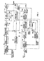
- Permanent magnet motor 12 includes a permanent magnet rotor 14 and a two-phase stator including a 0 ⁇ A winding 16 and a 0 ⁇ B winding 18.
- 0 ⁇ A winding 16 is utilized for driving the permanent magnet rotor.
- Winding 18 for 0 ⁇ B is energized for two-phase operation during start-up but thereafter is utilized as a sensing winding having a back EMF which is indicative of position and speed of rotor 14.
- a start decision circuit 20 is provided which controls starting and restarting of permanent magnet motor 12.
- An output of circuit 20 feeds a mode select switch 22 which provides for either a starting mode or a running mode for permanent magnet motor 12.
- permanent magnet motor 12 is operated in the two-phase mode with both windings 16 and 18 being driven. After the initial start-up, the permanent magnet motor is operated in the single phase mode when mode select switch 22 switches to run. At this time, winding 18, has a back EMF induced therein which is sensed by back EMF conditioning circuit 23.
- the output of back EMF conditioning circuit 23 is fed to the start circuit 20 and to a frequency to DC converter 24.
- the feedback signal from frequency to DC converter 24 is combined with the speed command signal in a speed command circuit 26.
- the output of speed command circuit 26 is a fed to a loop compensation circuit 28 and therefrom to a commutating switch 30.
- Commutating switch 30 also has an input from the back EMF conditioning circuit 23 when permanent magnet motor 12 is in a single phase run mode. This input from the back EMF conditioning circuit 23 is used to impart appropriate frequency and time characteristics to commutating switch 30. The output of commutating switch 30 is applied to 0 ⁇ A driver 32 which provides drive power input to winding 16.
- a DC voltage is applied to the start/restart command circuit 40, within start circuit 20, which in turn provides a constant DC signal input to the ramp generating cirucit 50.
- the ramp generating circuit 50 produces a decreasing ramp voltage which is supplied to a voltage controlled oscillator 60 and a start/run comparator 62.
- the start/run comparator 62 controls mode select switch 22 which selects a single or two-phase drive mode.
- An output of comparator 62 is also fed to restart decision circuit 70.
- the voltage controlled oscillator 60 generates an output signal, in response to the decreasing ramp input, which starts at DC and increases to a frequency approximately 10% of the synchronous frequency for permanent magnet motor 12.
- the start/run comparator 62 selects the two-phase drive mode and keeps the restart decision circuit in an off state.
- the increasing frequency generated by the ramping function input to the voltage controlled oscillator 60 is divided into two outputs 90° out of phase by a phase splitter circuit 64.
- the inphase output of splitter circuit 64 operates the commutating switch 30, which provides an output through drive amplifier 32 to drive winding 16.
- the quadrature output of splitter circuit 64 is fed to a power amplifying stage 34.
- the output of amplifier 34 drives winding 18 during two-phase operation.
- Permanent magnet motor 12 is driven in a two-phase mode until the ramping voltage applied to voltage oscillator 60 drops below a preset level.
- the ramping voltage output from ramping generator 50 falls below the preset level, single phase drive mode operation is initiated and the back EMF signal induced in winding 18 is processed by the back EMF conditioning circuit 23.
- the output of the back EMF conditioning circuit is sampled by the restart decision circuit 70.
- the restart decision circuit 70 determines if a run or a restart mode is to be commanded. Once a run mode is entered, the back EMF conditioning circuit processes the voltage induced in the sensing winding 28 and generates the required timing to the commutating switch 30 which is needed to obtain maximum efficiency.
- This back EMF voltage induced in winding 18 and processed by the back EMF conditioning circuit 23 provides wheel speed information to the restart decision circuit. After a predetermined sampling period the back EMF feedback voltage is tested and if its level is below a preset value, the restart decision circuit commands a restart. This sequence is repeated as necessary.
- the restart decision making circuit 70 remains active even during steady state single phase operation of permanent magnet motor 12, allowing wheel speed to be continuously monitored. In case of an unexpected wheel run down, the restart mode is again initiated.
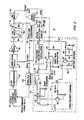
- Figure 3 shows the voltage waveforms present in circuit 10, at various points shown in Figure 2, during a start/restart cycle.
- a DC voltage is applied to the ramp generator circuit 50.
- DC voltage through resistor R1 charges a capacitor C1.
- Voltage V1 across capacitor C1 is shown in Figure 3.
- the output of ramp generator circuit 50 is a decreasing ramp voltage V2.
- Decreasing ramp voltage V2 is applied as an input to start/run comparator 62.
- the other input to start/run comparator 62 is a three volt DC reference voltage.
- mode select switch 22 switches to a run mode.
- the output, V21, of ramp generator circuit 50 is fed to voltage controlled oscillator 60.
- Voltage controlled oscillator 60 provides an output voltage V4 which is initially a zero frequency DC voltage which is changed to an increasing frequency output to drive permanent magnet motor 12 up to a suitable speed, which is typically 5% to 10% of synchronous speed.
- the output V4 of voltage controlled oscillator 60 is fed to the phase splitter circuit 64 which provides two outputs, V5A, V5B, which are 90° out of phase.
- the output V5A is fed to the commutating switch 30 and is used for toggling the speed loop command signal outputed by the loop compensation circuit 28.
- the output of the commutting switch 30 feeds the 0 ⁇ A drive 32 which provides the drive current to the 0 ⁇ A winding 16.
- the V5B output feeds the 0 ⁇ B driver 34 directly which provides the drive current to the 0 ⁇ B winding 18.
- the start/run comparator 62 changes state commanding the mode select switch 22 to change to the run mode. At this time winding 18 is no longer driven but acts as a sensing winding.
- the back EMF induced in winding 18 is fed to back RMF conditioning circuit 23.
- the output V6 of back EMF conditioning circuit 23 is fed to restart decision circuit 70.
- the conditioned back EMF, V6 is sampled.
- V6 is converted to a DC voltage across capacitors C3, which is proportional to wheel speed, in the restart decision circuit 70. If the voltage across capacitor C3 is below a preset value, determined by resistors R2 and R3, transistor Q1 is not turned on.
- the voltage, V7, across capacitor C2 therefore increases as shown in Figure 3 until the breakdown voltage of zener diode DZ1 is exceeded, at which point transistor Q2 is turned on and capacitor C1, in the ramp generating circuit 50, is discharged.
- the turning on of transistor Q2 causes the voltage V1 to drop to zero and the start cycle is again initiated.
- Voltage V2 is reset as shown at time t2 and then decreases until it falls below the run reference three voltage signal applied to comparator 62 at which time the mode select switch 22 is again switched to the run mode. If the output of the back EMF conditioning circuit 23 is large enough, the DC voltage across C3 will exceed the preset value and transistor Q1 will be turned on keeping capacitor C2 from charging and holding voltage V7 near zero preventing the start cycle from again being initiated. If during operation the output of the back EMF conditioning circuit 23 allows voltage V6 to decrease so that transistor Q1 is turned off, then capacitor C2 will charge increasing voltage V7 applied to zener diode DZ1. When the voltage V7 applied to DZ1 exceeds the breakdown level, transistor Q2 will be turned on again actuating the start cycle.
Landscapes
- Engineering & Computer Science (AREA)
- Power Engineering (AREA)
- Control Of Motors That Do Not Use Commutators (AREA)
- Motor And Converter Starters (AREA)
Applications Claiming Priority (2)
| Application Number | Priority Date | Filing Date | Title |
|---|---|---|---|
| US917586 | 1986-10-10 | ||
| US06/917,586 US4673849A (en) | 1986-10-10 | 1986-10-10 | Permanent magnet motor closed loop restarting system |
Publications (1)
| Publication Number | Publication Date |
|---|---|
| EP0268020A1 true EP0268020A1 (fr) | 1988-05-25 |
Family
ID=25439012
Family Applications (1)
| Application Number | Title | Priority Date | Filing Date |
|---|---|---|---|
| EP87111623A Withdrawn EP0268020A1 (fr) | 1986-10-10 | 1987-08-11 | Système de redémarrage à asservissement fermé pour un moteur à aimant permanent |
Country Status (3)
| Country | Link |
|---|---|
| US (1) | US4673849A (fr) |
| EP (1) | EP0268020A1 (fr) |
| JP (1) | JPS63103679A (fr) |
Families Citing this family (39)
| Publication number | Priority date | Publication date | Assignee | Title |
|---|---|---|---|---|
| JP2503230B2 (ja) * | 1987-06-17 | 1996-06-05 | 松下電器産業株式会社 | ブラシレスモ−タの駆動装置 |
| IT1211537B (it) * | 1987-11-18 | 1989-11-03 | Halsall Prod Ltd | Motore a corrente continua senza spazzole per motoventilatori pompe ed altre apparecchiature similari |
| US4928043A (en) * | 1988-11-14 | 1990-05-22 | Synektron Corporation | Back EMF sampling circuit for phase locked loop motor control |
| BR8901539A (pt) * | 1989-03-27 | 1990-10-30 | Brasil Compressores Sa | Processo e circuito eletronico para controle de motor de corrente continua sem escovas |
| US5124604A (en) * | 1989-06-15 | 1992-06-23 | Areal Technology Corp. | Disk drive motor |
| US5202616A (en) * | 1989-09-25 | 1993-04-13 | Silicon Systems, Inc. | Bipolar or unipolar drive back-EMF commutation sensing method |
| US4992710A (en) * | 1989-09-27 | 1991-02-12 | Seagate Technology, Inc. | Position detection for a brushless DC motor with sample time optimization |
| US5001405A (en) * | 1989-09-27 | 1991-03-19 | Seagate Technology, Inc. | Position detection for a brushless DC motor |
| US5311105A (en) * | 1990-02-14 | 1994-05-10 | Matsushita Electric Industrial Co. Ltd. | Brushless motor operating method and apparatus |
| US5028852A (en) * | 1990-06-21 | 1991-07-02 | Seagate Technology, Inc. | Position detection for a brushless DC motor without hall effect devices using a time differential method |
| US5254914A (en) * | 1990-06-29 | 1993-10-19 | Seagate Technology, Inc. | Position detection for a brushless DC motor without Hall effect devices using a mutual inductance detection method |
| US5703449A (en) * | 1990-10-19 | 1997-12-30 | Seiko Epson Corporation | Controller for brushless DC motor without position sensor |
| US5223772A (en) * | 1992-02-28 | 1993-06-29 | Sgs-Thomson Microelectronics, Inc. | Method and apparatus for providing the lock of a phase-locked loop system from frequency sweep |
| US5327053A (en) * | 1992-08-12 | 1994-07-05 | Seagate Technology, Inc. | Apparatus and method for detecting rotor position in a sensorless and brushless DC motor |
| US5313148A (en) * | 1992-08-21 | 1994-05-17 | Alliedsignal Inc. | Electronically commutated two-axis gyro control system |
| US5696430A (en) * | 1993-02-22 | 1997-12-09 | General Electric Company | Circuit, motor, and method generating a signal representing back EMF in an energized motor winding |
| US6080352A (en) * | 1994-07-11 | 2000-06-27 | Seagate Technologies, Inc. | Method of magnetizing a ring-shaped magnet |
| US5751131A (en) * | 1995-03-23 | 1998-05-12 | Alliedsignal, Inc. | Dynamic rate feedback PM motor starting technique |
| US5569990A (en) * | 1995-03-31 | 1996-10-29 | Seagate Technology, Inc. | Detection of starting motor position in a brushless DC motor |
| US5841252A (en) * | 1995-03-31 | 1998-11-24 | Seagate Technology, Inc. | Detection of starting motor position in a brushless DC motor |
| US5825145A (en) * | 1995-12-18 | 1998-10-20 | Siliconix Incorporated | Quiet commutation circuit for an electric motor |
| US5767643A (en) * | 1996-02-02 | 1998-06-16 | Siliconix Incorporated | Commutation delay generator for a multiphase brushless DC motor |
| US5736879A (en) * | 1996-02-02 | 1998-04-07 | Siliconix Incorporated | Closed-loop frequency-to-current converter with integrable capacitances |
| DE19781648T1 (de) * | 1996-03-15 | 1999-04-01 | Dana Corp | System zum Steuern des Betriebs eines Motors mit geschalteter Reluktanz zwischen einer Mehrphasen-Betriebsart und einer Betriebsart reduzierter Phase |
| US5861727A (en) * | 1996-04-17 | 1999-01-19 | Dana Corporation | System for controlling operation of a switched reluctance motor between multi-phase operating mode and a reduced phase operating mode |
| US5796194A (en) * | 1996-07-15 | 1998-08-18 | General Electric Company | Quadrature axis winding for sensorless rotor angular position control of single phase permanent magnet motor |
| US5796227A (en) * | 1997-02-18 | 1998-08-18 | Allied Signal Inc | Initialization damping for a permanent magnet motor |
| JP3483740B2 (ja) * | 1997-08-29 | 2004-01-06 | 株式会社東芝 | 洗濯機 |
| CN1520024A (zh) * | 1998-07-16 | 2004-08-11 | ������������ʽ���� | 不带位置传感器的电动机的控制方法及其控制装置 |
| JP2000134982A (ja) * | 1998-10-28 | 2000-05-12 | Internatl Business Mach Corp <Ibm> | スピンドルモータの起動方法およびそれを利用した装置 |
| DE10117252A1 (de) * | 2001-04-06 | 2002-10-17 | Bosch Gmbh Robert | Elektronisch kommutierter Elektromotor |
| DE10207549B4 (de) * | 2002-02-22 | 2004-05-06 | Aradex Ag | Verfahren und Vorrichtung zum Betrieb eines Synchronmotors |
| US7012391B2 (en) * | 2002-08-09 | 2006-03-14 | Seagate Technology Llc | Motor acceleration using continuous sequence of current limit values |
| US7514887B2 (en) * | 2003-10-24 | 2009-04-07 | A. O. Smith Corporation | Electrical machine and method of controlling the same |
| ATE371984T1 (de) * | 2004-05-12 | 2007-09-15 | Ebm Papst St Georgen Gmbh & Co | Elektronisch kommutierter zweipulsiger motor und verfahren zum starten eines solchen motors |
| CN101567656B (zh) * | 2008-04-23 | 2011-05-11 | 远翔科技股份有限公司 | 切换式调整电路及双线圈马达装置 |
| US8901867B2 (en) | 2011-04-28 | 2014-12-02 | Regal Beloit America, Inc. | Electrical machine, method of controlling an electrical machine, and system including an electrical machine |
| WO2013016505A2 (fr) * | 2011-07-27 | 2013-01-31 | Carrier Corporation | Procédé de démarrage progressif de moteur |
| US9559623B2 (en) | 2013-08-30 | 2017-01-31 | Regal Beloit America, Inc. | Method of controlling an electrical machine |
Citations (4)
| Publication number | Priority date | Publication date | Assignee | Title |
|---|---|---|---|---|
| US4097788A (en) * | 1975-12-17 | 1978-06-27 | Danfoss A/S | Control circuit for a self-starting electric motor |
| US4266432A (en) * | 1978-04-24 | 1981-05-12 | The Singer Company | Gyro motor control |
| US4275343A (en) * | 1978-12-28 | 1981-06-23 | The Charles Stark Draper Laboratory, Inc. | Back EMF controlled permanent magnet motor |
| US4455513A (en) * | 1982-07-26 | 1984-06-19 | Imec Corporation | Self-starting transducerless, brushless D.C. motor controller |
Family Cites Families (4)
| Publication number | Priority date | Publication date | Assignee | Title |
|---|---|---|---|---|
| JPS525418A (en) * | 1975-07-02 | 1977-01-17 | Ichikoh Ind Ltd | Drive circuit of contactless dc motor |
| DE2949947C2 (de) * | 1979-12-12 | 1982-06-24 | Braun Ag, 6000 Frankfurt | Schaltungsanordnung zum Steuern und Regeln eines kollektorlosen Elektromotors mit einem permanentmagnetischen Läufer |
| US4492902A (en) * | 1983-06-03 | 1985-01-08 | Allied Corporation | Permanent magnetic motor common leg impedance compensation means |
| DE3540011A1 (de) * | 1984-11-13 | 1986-05-15 | Hewlett-Packard Co., Palo Alto, Calif. | Verfahren und treiberschaltung zum antreiben eines buerstenlosen gleichstrommotors |
-
1986
- 1986-10-10 US US06/917,586 patent/US4673849A/en not_active Expired - Fee Related
-
1987
- 1987-08-11 EP EP87111623A patent/EP0268020A1/fr not_active Withdrawn
- 1987-10-09 JP JP62256123A patent/JPS63103679A/ja active Pending
Patent Citations (4)
| Publication number | Priority date | Publication date | Assignee | Title |
|---|---|---|---|---|
| US4097788A (en) * | 1975-12-17 | 1978-06-27 | Danfoss A/S | Control circuit for a self-starting electric motor |
| US4266432A (en) * | 1978-04-24 | 1981-05-12 | The Singer Company | Gyro motor control |
| US4275343A (en) * | 1978-12-28 | 1981-06-23 | The Charles Stark Draper Laboratory, Inc. | Back EMF controlled permanent magnet motor |
| US4455513A (en) * | 1982-07-26 | 1984-06-19 | Imec Corporation | Self-starting transducerless, brushless D.C. motor controller |
Also Published As
| Publication number | Publication date |
|---|---|
| US4673849A (en) | 1987-06-16 |
| JPS63103679A (ja) | 1988-05-09 |
Similar Documents
| Publication | Publication Date | Title |
|---|---|---|
| US4673849A (en) | Permanent magnet motor closed loop restarting system | |
| US4841216A (en) | Engine start type VSCF generating system | |
| US4455513A (en) | Self-starting transducerless, brushless D.C. motor controller | |
| US4700116A (en) | System for controlling brushless DC motor | |
| US5397972A (en) | Start-up procedure for a brushless, sensorless motor | |
| US5327053A (en) | Apparatus and method for detecting rotor position in a sensorless and brushless DC motor | |
| US5285135A (en) | Automatic adjustment of commutation delay for brushless DC motor for improved efficiency | |
| EP0089150B1 (fr) | Entraînement ayant un moteur à courant continu sans balai | |
| US6438321B1 (en) | Control of high speed DC motor vertical voltage vector component | |
| GB2206751A (en) | Starting a variable speed constant frequency generating system | |
| US4500830A (en) | Current control circuit for a plurality of loads | |
| JP3577245B2 (ja) | モータ起動制御装置 | |
| US5751131A (en) | Dynamic rate feedback PM motor starting technique | |
| US4952860A (en) | Motor control system | |
| JP3248248B2 (ja) | ブラシレス直流モータの駆動装置 | |
| JPH06343285A (ja) | ブラシレスモータの停止方法 | |
| JP2682164B2 (ja) | ブラシレスモータの起動方法及び起動装置 | |
| JP2887320B2 (ja) | ブラシレスモータの起動方法及び起動装置 | |
| JP3263993B2 (ja) | センサレスモータの起動方法 | |
| JP2778816B2 (ja) | センサレス・スピンドルモータ制御回路 | |
| JP2940281B2 (ja) | ブラシレス直流モータの駆動装置 | |
| JPH05168270A (ja) | モータ回転速度制御回路および制御方式 | |
| JP2906926B2 (ja) | ブラシレスモータの制御装置 | |
| JPH072040B2 (ja) | 電動発電機の起動トルク制御装置 | |
| JP2004096915A (ja) | 同期電動機の制御方法及び同期電動機の制御装置 |
Legal Events
| Date | Code | Title | Description |
|---|---|---|---|
| PUAI | Public reference made under article 153(3) epc to a published international application that has entered the european phase |
Free format text: ORIGINAL CODE: 0009012 |
|
| AK | Designated contracting states |
Kind code of ref document: A1 Designated state(s): DE FR GB IT |
|
| 17P | Request for examination filed |
Effective date: 19881108 |
|
| 17Q | First examination report despatched |
Effective date: 19901015 |
|
| STAA | Information on the status of an ep patent application or granted ep patent |
Free format text: STATUS: THE APPLICATION IS DEEMED TO BE WITHDRAWN |
|
| 18D | Application deemed to be withdrawn |
Effective date: 19910226 |
|
| RIN1 | Information on inventor provided before grant (corrected) |
Inventor name: KLUSS, WALTER Inventor name: PARFOMAK, WALTER Inventor name: SEARS, JEROME |