EP0268038A2 - System zur Verarbeitung von graphischen Daten - Google Patents
System zur Verarbeitung von graphischen Daten Download PDFInfo
- Publication number
- EP0268038A2 EP0268038A2 EP87113675A EP87113675A EP0268038A2 EP 0268038 A2 EP0268038 A2 EP 0268038A2 EP 87113675 A EP87113675 A EP 87113675A EP 87113675 A EP87113675 A EP 87113675A EP 0268038 A2 EP0268038 A2 EP 0268038A2
- Authority
- EP
- European Patent Office
- Prior art keywords
- area
- image
- boundary
- display
- map
- Prior art date
- Legal status (The legal status is an assumption and is not a legal conclusion. Google has not performed a legal analysis and makes no representation as to the accuracy of the status listed.)
- Granted
Links
Images


Classifications
-
- G—PHYSICS
- G09—EDUCATION; CRYPTOGRAPHY; DISPLAY; ADVERTISING; SEALS
- G09G—ARRANGEMENTS OR CIRCUITS FOR CONTROL OF INDICATING DEVICES USING STATIC MEANS TO PRESENT VARIABLE INFORMATION
- G09G5/00—Control arrangements or circuits for visual indicators common to cathode-ray tube indicators and other visual indicators
- G09G5/36—Control arrangements or circuits for visual indicators common to cathode-ray tube indicators and other visual indicators characterised by the display of a graphic pattern, e.g. using an all-points-addressable [APA] memory
- G09G5/39—Control of the bit-mapped memory
- G09G5/393—Arrangements for updating the contents of the bit-mapped memory
-
- G—PHYSICS
- G06—COMPUTING OR CALCULATING; COUNTING
- G06T—IMAGE DATA PROCESSING OR GENERATION, IN GENERAL
- G06T11/00—Two-dimensional [2D] image generation
- G06T11/20—Drawing from basic elements
Definitions
- the present invention concerns a graphics processing system comprising means for creating a pixel map of an image for display on display means.
- Graphics processing systems can take many forms. There are systems which are dedicated to graphics such as those used in computer aided design. However many general purpose and other processing systems also provide graphics functions. For example, many text processing systems are provided with facilities for creating charts such as histograms, pie charts, and special images.
- graphics processing system as used herein is consequently intended to be interpreted generally to include such systems, that is any system in which information can be represented pictorially rather than or as well as alphanumerically and one or more areas making up an image or picture for display can be defined in terms of the boundaries of those areas.
- an "area” is meant a plane figure whose outline or boundary consists of lines and/or curves. Areas can be convex, non-convex and can contain holes. In general terms, therefore, an "area” means a general form of boundary, possibly with holes and self intersections.
- a polygon is a particular form of area which has a boundary formed from straight lines. An area can be defined in a graphics system in many ways. Generally, however, an area will be defined in terms of line or curve segments. In the case of a polygon, the definitions of the vertices and the straight line segments joining the vertices suffice.
- Areas will often be filled with colour, patterns and/or shading. In general, this is done to make an image more effective. For example, it can be used to enable areas to be more readily distinguished (eg in bar and pie charts), for highlighting areas of particular importance, or to make images of a three dimensional object more realistic (eg in modelling and/or computer aided design systems).
- the shading itself can, for example, be performed using Gouraud shading. This provides for the smooth shading of flat areas of an image. If an area for display is defined in terms of its edges, it is necessary to determine which points on the final image fall within the area in order that the appropriate locations in the image buffer may be set so as to give the corresponding pixels in the image the correct colour and/or intensity.
- an additional image map called a spare bit plane is provided in addition to the image buffer and each area forming part of the image is separately processed using this additional map.
- the pixel locations in the additional map need to be reset.
- the edges of the area are computed and locations are set in the additional map.
- the edge of the area are computed and locations are set in the additional map.
- a technique of this type is described in by Ackland and West in their article entitled “The Edge Flag Algorithm - A Fill Method For Raster Scan Displays" which was published in IEEE Transactions in Computers, Vol C30, pp 41 to 48 in 1981.
- the present invention therefore, is directed to graphics processing system comprising a source of image data defining the boundary of an area forming at least part of an image to be displayed on display means, image storage for a map of the image in terms of the individual picture elements for each of plural display lines, and means for generating the image map from the image data.
- the means for generating the image map from the image data comprises a plurality of paired storage locations, the pairs of storage locations being associated with corresponding display lines, and processing means which initially processes the boundary of the area so as to determine the display lines and displacement along those lines at which sequential boundary points are to be displayed and stores the displacements of the points in free ones of the pair of locations for the appropriate display lines as they are determined.
- the processing means are arranged to continue the initial processing of the boundary either until the displacement of a position is computed where both storage locations of the appropriate display line are occupied by displacement values different from that just computed, in which case the area is non-convex in the direction of the display lines, or until the complete boundary has been processed and at most two different displacement values per display line have been detected and stored in the appropriate storage locations, in which case the area is at least one-dimensionally convex in the direction of the display lines, and then to process further the area in either a first or a second further processing mode in accordance with the determination of whether the area is convex or non-convex in said direction.
- the graphics processing system in accordance with the present invention obviates the need to set up and to process a spare bit plane for shapes which are convex in the direction of the display lines.
- areas which are convex in the direction of the display lines it therefore avoids the overhead of having to interrogate each storage location in the additional image buffer to determine the points at which the filling operation is to be turned on and off. It will still be necessary to process areas which are non-convex in this direction using conventional techniques.
- the invention provides significant processing advantages over the prior art approaches.
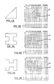
- Figures 1A, 2A and 3A show in a generalised form three simple shapes or areas which it might be desired to display in a graphics processing system.
- the areas could define display objects in themselves, or the could form part of a more complex object for display.
- the graphics processing system is a word or text processing system with image processing functions they could, for example, represent symbols for use in labelling or generating graphs.
- the graphics processing system is able to process and display representations of three dimensional objects, the areas could form surfaces of such an object.
- Graphics processing systems come in many different guises.
- the display subsystems that they incorporate also come in many forms.
- display subsystems are based on elemental image techniques where an image is made up of a matrix of individual picture elements. Examples of such display sub-systems are raster-scanned display screens and dot matrix printers. It should be noted that references to displaying and the like in this specification are intended to cover displaying by means of a printer.
- an image buffer can be provided in which an image to be displayed is stored in terms of the individual picture elements (pixels) making up the image, and then the individual elements are accessed in synchronism with the scanning of the display device.
- the image buffer will be accessed repeatedly and is generally termed a refresh buffer.
- the storage for the image may be provided by the display device itself as is the case, for example, in gas panel displays.
- the present invention is directed to graphics processing systems incorporating image storage for an image to be displayed, in which storage a map of the image is built up in terms of the individual picture elements on each of plural display lines.
- a display line is simply meant a line of individual picture elements.
- a display line could, but need not be a scan line on a raster-scanned display.
- Figures 1B, 2B and 3B illustrate, respectively, how the shapes shown in Figures 1A, 2A and 3A could be represented in the image storage of a graphics processing system by setting the bits corresponding to the appropriate pixel locations. In these figures, a set bit is indicated by a "1". It should be noted that Figures 1B, 2B and 3B are merely logical representations of the storage of image information and that the physical storage of the information need not be in the form shown (eg the information could be stored in a linear form rather than two dimensionally).
- the image buffer of the graphics processing system is arranged on a pixel basis, the system would require an immense amount of storage if all the possible images to be displayed were stored on the same basis. In the case of images made up of areas which are filled with colour, shading and/or a pattern this would be particularly inefficient. In practice it is usual to store such images in alternative, more efficient ways.
- One possible way is in terms of data defining the edges and possible the colour and/or shading and/or pattern for the areas making up the image.
- the present invention is concerned with systems of this general sort where the areas making up the image can be defined in terms of the boundaries of those areas.
- Figure 3 shows a logical arrangement of elements of a prior art arrangement such as that mentioned above.
- the prior system comprises a cathode ray tube device 30, driven by refresh logic 28 using pixel information in an image buffer 26.
- a buffer called a spare bit plane 24 is provided in addition to the image buffer 28.
- the original area definitions can be stored in image definition storage 20 in terms of its edges and information defining the colour and/or shading and/or pattern for the area.
- the detailed storage methodology used is not important to the functioning of the prior system.
- the definitions of the data defining each area could be linked by a conventional data structure such as linked lists, tables and so on. Alternatively the area definition data could be down loaded from a host processor or generated in real-time rather than being stored in storage 20.
- the spare bit plane locations Before each area is processed, the spare bit plane locations have to be reset. Then, each edge of the area is processed in turn to determine the individual pixel locations crossed by the edges and the corresponding locations in the spare bit plane are set. The processing is performed by the control logic 22. When all the edges of the area have been processed and the corresponding bit positions in the spare bit plane set, it is then possible to set up the area in the image buffer 28.
- the spare bit plane could have the same logical structure as the image buffer (see Figs. 1B, 2B, 3B and the description thereof).
- the filled area is created in the image buffer by scanning the spare bit plane and the buffer in synchronism and alternately starting writing and stopping writing information into the buffer on crossing a set location in the spare bit plane. At the same time the set locations in the spare bit plane can be reset to avoid needing a separate resetting operation before processing a subsequent area.
- the actual information written for the individual picture elements in the image buffer is dependant on the colour and/or shading and/or pattern information for that area. Subsequent areas can then be processed using the spare bit plane until a complete image including the all the filled areas is stored in the image buffer.
- the present invention provides improved performance in that, for many images, it is not necessary to use the spare bit plane when filling in areas.
- the invention is based on the principle that a straight line drawn through a convex shape will only cross the boundary of that shape at two places at most. Thus, any straight line drawn through the triangle in Figure 1A will cross the boundary of the triangle at two places at most.
- the "I" shape in Figure 2A can be said to be “one-dimensionally convex” in the horizontal direction because any horizontal line drawn through it will cross the boundary at two places at most. It is not however convex in the vertical direction because a vertical line to the left or right of the central part of the "I" will cross the boundary at four places.
- the "H" shape in Figure 3A is convex in the vertical, but not in the horizontal direction.
- the normal method for determining the convexity of a polygon uses Euclid's Theorem.
- a polygon is convex if the sum of its interior angles is not greater than 360 degrees. It would be possible therefore to determine whether a polygon is convex using the signs of the vector cross products of the polygon edges or by counting polygon vertex inflexions. In either case, however, this involves a pre-processing pass of the polygon vertices and significant calculation to determine whether the polygon is convex.
- this technique cannot be used for areas in general (unless the area is de-composed into straight line approximations), but only for polygons.
- the present invention overcomes the disadvantages of the prior art by the provision of a logical structured storage element called a convex area table.
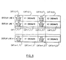
- a convex area table A possible logical configuration for this storage element is shown in Figure 6.
- the convex area table shown in Figure 6 comprises the capacity to store two "x" ordinate values for each of the scan lines on the display image. It is assumed in Figure 6 and in the following description that the "display lines" are horizontal. Figure 6 also shows an "in-use flag" for each of the storage locations for the "x" ordinates, although this is not essential as will be explained later.
- Figure 5 shows an arrangement of logical elements, including the convex area table 32, of a graphics processing system in accordance with the present invention.
- Logical elements which are also provided in the prior art system have the same numbering as in Figure 3.
- the original area definitions can be stored in the image definition storage 20 in terms of its edge and in-fill information defining the colour and/or shading and/or pattern for the area.
- the detailed storage methodology used is not important to the functioning of the present system.
- the definitions of the data defining each area could be linked by a conventional data structure such as linked lists, tables and so on.
- the provision of the image definition storage 20 is not essential as the area definition data could, for example, be generated in real time or down loaded from a host processor connected to the graphics processing system.
- the convex area table Before each area is processed, the convex area table needs to be reset. Then, as in the prior system, each edge of the area is processed in turn. To determine the individual pixel locations crossed by the edges. In the system of Figure 5 this processing is performed by the control logic 22 ⁇ which differs in operation at least from the control logic 22 in Figure 3 as will be apparent from the following.
- the control logic 22 ⁇ computes the display line and the displacement along the display line at which sequential incremental positions along the edge currently being processed are to be displayed. This can be done using any suitable algorithm, for example Bresenham's algorithm as described on pages 433-436 of Foley and Van Dam's book referred to earlier. If the display line on which a particular point is to be displayed differs from the immediately preceding point on that edge the control logic 22 ⁇ then examines the pair of locations in the convex area table corresponding to the appropriate display line to determine whether one or both are already occupied by displacement values.
- the newly calculated "x" ordinate value is stored in the free one of the paired locations. If it is determined that the newly computed "x" ordinate is the same as an "x" ordinate value already stored in the pair of locations for the current scan line, the newly computed "x” ordinate is discarded. If both of the locations for that scan line are occupied by "x" ordinate values different from that just computed, then the logic 22 ⁇ designates the area under consideration non-convex and causes the area to be processed using the spare bit plane.
- the first filling mode the contents of the convex area table are used to determine the individual picture element locations to be set in the image buffer. It should be noted that this operation will normally be independent of the scanning of the image buffer in synchronism with the scanning of the display for actually displaying of the image.
- the convex area table is examined by the control logic 22 ⁇ . If no "x" ordinate (displacement) values for a particular display line have been stored, this means that no part of the area lies on that display line and, consequently, that the line can be ignored as far as that area is concerned.
- the spare bit plane is used in a manner similar to that known from the prior art.
- the information already stored in the convex area table can be used when drawing the boundary information in the spare bit plane.
- the locations read can be reset in preparation for processing a subsequent area.
- in-use flags simplifies the control of the convex area table.
- the table is reset before the processing of an area is started, it is only necessary to reset the flags. If, on the other hand they are not provided, all the displacement values will have to be reset to some value which represents, for example, an invalid pixel location.
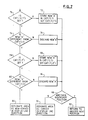
- Figure 7 is a flow diagram of a particular algorithm for determining whether an area is convex or not in the direction of the display lines for an image using a convex area table with in-use flags.
- a first test, 70 is made to determine whether the first one of the appropriate pair of locations is occupied. If it is not, then the newly computed "x" ordinate (displacement) value is stored, 72, in that first location the in use flag for that location is set, the next position on the boundary of the area can be considered, 92. If it was already occupied, the newly "x" ordinate value is compared, 74 to the stored value. If they compare equal, the newly computed value is discarded, 76, and the next position on the boundary of the area is considered, 92. If they are not equal, the second one of the pair of locations is then considered.
- a test, 78 is made to determine whether the second "x" ordinate value is occupied. If it is not, then the newly computed "x" ordinate value is stored, 80, therein, the in-use flag for that location is set and then the next position on the boundary of the area can be computed. If it was already occupied, the newly computed "x" ordinate value is compared, 82, to the value stored in said second location. If they compare equal, the newly computed "x" ordinate value is discarded, 84, and the next position on the boundary of the area is considered, 92. If they are not equal, then the control logic 22 ⁇ designates, 86, the area as being non-convex in the direction of the display lines and processing of the area using the spare bit plane is invoked.
- control logic 22 ⁇ designates, 90, the area as being at least one-dimensionally convex in the direction of the display lines and the area can be filled without using the spare bit plane.
- FIG 8. A specific implementation of graphics processing system in accordance with the invention is shown in Figure 8.
- the personal computer comprises a microprocessor 40, main storage 42, a keyboard and a cathode ray tube display 30.
- the operation of the cathode ray tube device is controlled by refresh circuitry 28.
- the microprocessor can be of any suitable type as will be evident to the person skilled in the art.
- the keyboard is connected to the bus via a keyboard adapter 50.
- Backing storage 44 with an associated I/O adapter 46 can also be provided.
- the individual units are connected to one another by a bus comprising data bus lines 56, control bus lines 52 and an interrupt line 54 in a conventional manner.
- the personal computer could, of course be provided, in a conventional manner, with connections to further personal computers and/or host processors.
- FIG. 6 The functional units shown in Figure 6 are implemented by means of suitable programming.
- a first part 60 of main memory 42 is reserved for programs and data.
- computer software is stored, which, in combination with the hardware elements of the system provide the functions of the control logic 22 ⁇ shown in Figure 6.
- the data specifying the image to be displayed ie the data contained in the image definition storage 20 shown in Figure 6) can be stored in this first part of main memory.
- Parts 62, 64 and 66 of storage in the main memory are provided, respectively, for the convex area table 32, the spare bit plane 24 and the refresh buffer 26 shown in Figure 6. It should be noted that Figure 8 shows the various parts 60, 62, 64 and 66 of storage as unitary blocks purely for the simplicity of illustration.
- the various parts of storage could be distributed throughout main memory. Indeed, it is also possible for part or all of the data, and for software as necessary to be stored on backing storage and for this to be brought into main memory only when needed.
- the display lines mentioned on Figure 6 correspond to the scan lines of a display screen or a raster printer head, this is not essential.
- the image buffer could for example be loaded by accessing it using horizontal sweeps, whereas the display itself could be scanned vertically and consequently the image buffer read vertically during scanning of the display screen and vice versa.
- the image storage may be performed by the display itself (eg gas panel displays) rather than an image buffer.
Landscapes
- Engineering & Computer Science (AREA)
- Physics & Mathematics (AREA)
- General Physics & Mathematics (AREA)
- Theoretical Computer Science (AREA)
- Computer Hardware Design (AREA)
- Image Generation (AREA)
- Controls And Circuits For Display Device (AREA)
- Digital Computer Display Output (AREA)
Applications Claiming Priority (2)
| Application Number | Priority Date | Filing Date | Title |
|---|---|---|---|
| GB8627552A GB2198019B (en) | 1986-11-18 | 1986-11-18 | Graphics processing system |
| GB8627552 | 1986-11-18 |
Publications (3)
| Publication Number | Publication Date |
|---|---|
| EP0268038A2 true EP0268038A2 (de) | 1988-05-25 |
| EP0268038A3 EP0268038A3 (en) | 1990-10-24 |
| EP0268038B1 EP0268038B1 (de) | 1993-02-03 |
Family
ID=10607532
Family Applications (1)
| Application Number | Title | Priority Date | Filing Date |
|---|---|---|---|
| EP87113675A Expired - Lifetime EP0268038B1 (de) | 1986-11-18 | 1987-09-18 | System zur Verarbeitung von graphischen Daten |
Country Status (5)
| Country | Link |
|---|---|
| US (1) | US4899294A (de) |
| EP (1) | EP0268038B1 (de) |
| JP (1) | JPH07120427B2 (de) |
| DE (1) | DE3784014T2 (de) |
| GB (1) | GB2198019B (de) |
Families Citing this family (6)
| Publication number | Priority date | Publication date | Assignee | Title |
|---|---|---|---|---|
| US5060172A (en) * | 1989-07-06 | 1991-10-22 | Digital Equipment Corporation | Method and apparatus for displaying smooth-shaded objects |
| US5432898A (en) * | 1993-09-20 | 1995-07-11 | International Business Machines Corporation | System and method for producing anti-aliased lines |
| US5463723A (en) * | 1993-09-20 | 1995-10-31 | International Business Machines Corporation | Method and apparatus for filling polygons |
| AU3313895A (en) * | 1994-10-14 | 1996-04-26 | Compaq Computer Corporation | Method and apparatus for determining simple convex polygons |
| US7502057B2 (en) * | 2002-06-20 | 2009-03-10 | Hewlett-Packard Development Company, L.P. | Method and apparatus for color non-uniformity correction in a digital camera |
| TWI383336B (zh) * | 2008-11-14 | 2013-01-21 | Delta Electronics Inc | 多邊形快速填色方法 |
Family Cites Families (9)
| Publication number | Priority date | Publication date | Assignee | Title |
|---|---|---|---|---|
| US4580231A (en) * | 1978-09-15 | 1986-04-01 | Alphatype Corporation | Ultrahigh resolution photocomposition system employing electronic character generation from magnetically stored data |
| US4425559A (en) * | 1980-06-02 | 1984-01-10 | Atari, Inc. | Method and apparatus for generating line segments and polygonal areas on a raster-type display |
| NL8300872A (nl) * | 1983-03-10 | 1984-10-01 | Philips Nv | Multiprocessor-rekenmachinesysteem voor het tot een gekleurde afbeelding verwerken van in een hierarchische datastruktuur gedefinieerde objekt-elementen. |
| JPS5971093A (ja) * | 1982-10-18 | 1984-04-21 | 株式会社日立製作所 | 塗潰し図形発生装置 |
| DE3376594D1 (en) * | 1983-12-22 | 1988-06-16 | Ibm | Area filling hardware for a colour graphics frame buffer |
| EP0157254B1 (de) * | 1984-03-16 | 1990-08-08 | Ascii Corporation | Steuersystem für ein Bildschirmsichtgerät |
| US4677574A (en) * | 1984-08-20 | 1987-06-30 | Cromemco, Inc. | Computer graphics system with low memory enhancement circuit |
| US4791582A (en) * | 1985-09-27 | 1988-12-13 | Daikin Industries, Ltd. | Polygon-filling apparatus used in a scanning display unit and method of filling the same |
| US4788538A (en) * | 1986-11-17 | 1988-11-29 | Lotus Development Corporation | Method and apparatus for determining boundaries of graphic regions |
-
1986
- 1986-11-18 GB GB8627552A patent/GB2198019B/en not_active Expired - Lifetime
-
1987
- 1987-09-18 DE DE8787113675T patent/DE3784014T2/de not_active Expired - Fee Related
- 1987-09-18 EP EP87113675A patent/EP0268038B1/de not_active Expired - Lifetime
- 1987-10-16 JP JP62259879A patent/JPH07120427B2/ja not_active Expired - Lifetime
- 1987-11-18 US US07/121,976 patent/US4899294A/en not_active Expired - Fee Related
Also Published As
| Publication number | Publication date |
|---|---|
| JPH07120427B2 (ja) | 1995-12-20 |
| DE3784014D1 (de) | 1993-03-18 |
| GB8627552D0 (en) | 1986-12-17 |
| GB2198019A (en) | 1988-06-02 |
| DE3784014T2 (de) | 1993-08-19 |
| GB2198019B (en) | 1990-09-26 |
| EP0268038B1 (de) | 1993-02-03 |
| JPS63137378A (ja) | 1988-06-09 |
| US4899294A (en) | 1990-02-06 |
| EP0268038A3 (en) | 1990-10-24 |
Similar Documents
| Publication | Publication Date | Title |
|---|---|---|
| US4907174A (en) | Z-buffer allocated for window identification | |
| US5426723A (en) | System and method for scaling graphic images | |
| EP0323558B1 (de) | Verfahren zum Füllen von Polygonen | |
| EP0356103B1 (de) | Verfahren und Prozessor zur Abtastumsetzung | |
| US4475104A (en) | Three-dimensional display system | |
| US4679041A (en) | High speed Z-buffer with dynamic random access memory | |
| US4897805A (en) | Method and apparatus for performing polygon fills in graphical applications | |
| US4609917A (en) | Three-dimensional display system | |
| US5570460A (en) | System and method for volume rendering of finite element models | |
| US4730261A (en) | Solids modelling generator | |
| US5040130A (en) | Computer graphics boundary--defined area clippping and extraneous edge deletion method | |
| US4924414A (en) | Apparatus and method for obtaining priority numbers for drawing figures forming a display figure | |
| US4945495A (en) | Image memory write control apparatus and texture mapping apparatus | |
| JPH0126072B2 (de) | ||
| US20220366621A1 (en) | Systems for Generating Anti-Aliased Vector Objects | |
| US5719598A (en) | Graphics processor for parallel processing a plurality of fields of view for multiple video displays | |
| US5295234A (en) | Apparatus for displaying a three dimensional object which appears substantially the same in different display directions by modifying stored image data by a scale factor | |
| EP0268038B1 (de) | System zur Verarbeitung von graphischen Daten | |
| CA1319996C (en) | Method and apparatus for decomposing a quadrilateral figure for display and manipulation by a computer system | |
| JPH01296389A (ja) | 図形処理方法及びその装置 | |
| US5117485A (en) | Method and apparatus for sorting line segments for display and manipulation by a computer system | |
| US5157766A (en) | Boundary drawing and area filling logic for a display system | |
| EP0568360B1 (de) | Grafisches System mit Anwendung von quadratischen Polynomelementen | |
| KR0145709B1 (ko) | 컴퓨터 그래픽 시스템 | |
| JP3493745B2 (ja) | 図形描画装置 |
Legal Events
| Date | Code | Title | Description |
|---|---|---|---|
| PUAI | Public reference made under article 153(3) epc to a published international application that has entered the european phase |
Free format text: ORIGINAL CODE: 0009012 |
|
| AK | Designated contracting states |
Kind code of ref document: A2 Designated state(s): DE FR GB |
|
| 17P | Request for examination filed |
Effective date: 19880910 |
|
| PUAL | Search report despatched |
Free format text: ORIGINAL CODE: 0009013 |
|
| AK | Designated contracting states |
Kind code of ref document: A3 Designated state(s): DE FR GB |
|
| 17Q | First examination report despatched |
Effective date: 19920427 |
|
| GRAA | (expected) grant |
Free format text: ORIGINAL CODE: 0009210 |
|
| AK | Designated contracting states |
Kind code of ref document: B1 Designated state(s): DE FR GB |
|
| REF | Corresponds to: |
Ref document number: 3784014 Country of ref document: DE Date of ref document: 19930318 |
|
| ET | Fr: translation filed | ||
| PLBE | No opposition filed within time limit |
Free format text: ORIGINAL CODE: 0009261 |
|
| STAA | Information on the status of an ep patent application or granted ep patent |
Free format text: STATUS: NO OPPOSITION FILED WITHIN TIME LIMIT |
|
| 26N | No opposition filed | ||
| PGFP | Annual fee paid to national office [announced via postgrant information from national office to epo] |
Ref country code: GB Payment date: 19950822 Year of fee payment: 9 |
|
| PGFP | Annual fee paid to national office [announced via postgrant information from national office to epo] |
Ref country code: FR Payment date: 19950911 Year of fee payment: 9 |
|
| PGFP | Annual fee paid to national office [announced via postgrant information from national office to epo] |
Ref country code: DE Payment date: 19950921 Year of fee payment: 9 |
|
| PG25 | Lapsed in a contracting state [announced via postgrant information from national office to epo] |
Ref country code: GB Effective date: 19960918 |
|
| PG25 | Lapsed in a contracting state [announced via postgrant information from national office to epo] |
Ref country code: FR Effective date: 19960930 |
|
| GBPC | Gb: european patent ceased through non-payment of renewal fee |
Effective date: 19960918 |
|
| PG25 | Lapsed in a contracting state [announced via postgrant information from national office to epo] |
Ref country code: DE Effective date: 19970603 |
|
| REG | Reference to a national code |
Ref country code: FR Ref legal event code: ST |
|
| REG | Reference to a national code |
Ref country code: FR Ref legal event code: ST |