EP0268096A1 - Machine à scier à lame circulaire - Google Patents
Machine à scier à lame circulaire Download PDFInfo
- Publication number
- EP0268096A1 EP0268096A1 EP87115385A EP87115385A EP0268096A1 EP 0268096 A1 EP0268096 A1 EP 0268096A1 EP 87115385 A EP87115385 A EP 87115385A EP 87115385 A EP87115385 A EP 87115385A EP 0268096 A1 EP0268096 A1 EP 0268096A1
- Authority
- EP
- European Patent Office
- Prior art keywords
- clamping
- inclined surfaces
- circular saw
- profile groove
- clamping block
- Prior art date
- Legal status (The legal status is an assumption and is not a legal conclusion. Google has not performed a legal analysis and makes no representation as to the accuracy of the status listed.)
- Withdrawn
Links
Images



Classifications
-
- B—PERFORMING OPERATIONS; TRANSPORTING
- B23—MACHINE TOOLS; METAL-WORKING NOT OTHERWISE PROVIDED FOR
- B23Q—DETAILS, COMPONENTS, OR ACCESSORIES FOR MACHINE TOOLS, e.g. ARRANGEMENTS FOR COPYING OR CONTROLLING; MACHINE TOOLS IN GENERAL CHARACTERISED BY THE CONSTRUCTION OF PARTICULAR DETAILS OR COMPONENTS; COMBINATIONS OR ASSOCIATIONS OF METAL-WORKING MACHINES, NOT DIRECTED TO A PARTICULAR RESULT
- B23Q3/00—Devices holding, supporting, or positioning work or tools, of a kind normally removable from the machine
- B23Q3/005—Guides for workpieces
-
- B—PERFORMING OPERATIONS; TRANSPORTING
- B23—MACHINE TOOLS; METAL-WORKING NOT OTHERWISE PROVIDED FOR
- B23D—PLANING; SLOTTING; SHEARING; BROACHING; SAWING; FILING; SCRAPING; LIKE OPERATIONS FOR WORKING METAL BY REMOVING MATERIAL, NOT OTHERWISE PROVIDED FOR
- B23D47/00—Sawing machines or sawing devices working with circular saw blades, characterised only by constructional features of particular parts
- B23D47/04—Sawing machines or sawing devices working with circular saw blades, characterised only by constructional features of particular parts of devices for feeding, positioning, clamping, or rotating work
-
- B—PERFORMING OPERATIONS; TRANSPORTING
- B23—MACHINE TOOLS; METAL-WORKING NOT OTHERWISE PROVIDED FOR
- B23Q—DETAILS, COMPONENTS, OR ACCESSORIES FOR MACHINE TOOLS, e.g. ARRANGEMENTS FOR COPYING OR CONTROLLING; MACHINE TOOLS IN GENERAL CHARACTERISED BY THE CONSTRUCTION OF PARTICULAR DETAILS OR COMPONENTS; COMBINATIONS OR ASSOCIATIONS OF METAL-WORKING MACHINES, NOT DIRECTED TO A PARTICULAR RESULT
- B23Q1/00—Members which are comprised in the general build-up of a form of machine, particularly relatively large fixed members
- B23Q1/25—Movable or adjustable work or tool supports
- B23Q1/26—Movable or adjustable work or tool supports characterised by constructional features relating to the co-operation of relatively movable members; Means for preventing relative movement of such members
- B23Q1/28—Means for securing sliding members in any desired position
-
- B—PERFORMING OPERATIONS; TRANSPORTING
- B25—HAND TOOLS; PORTABLE POWER-DRIVEN TOOLS; MANIPULATORS
- B25B—TOOLS OR BENCH DEVICES NOT OTHERWISE PROVIDED FOR, FOR FASTENING, CONNECTING, DISENGAGING, OR HOLDING
- B25B1/00—Vices
- B25B1/06—Arrangements for positively actuating jaws
- B25B1/10—Arrangements for positively actuating jaws using screws
- B25B1/103—Arrangements for positively actuating jaws using screws with one screw perpendicular to the jaw faces, e.g. a differential or telescopic screw
-
- B—PERFORMING OPERATIONS; TRANSPORTING
- B25—HAND TOOLS; PORTABLE POWER-DRIVEN TOOLS; MANIPULATORS
- B25B—TOOLS OR BENCH DEVICES NOT OTHERWISE PROVIDED FOR, FOR FASTENING, CONNECTING, DISENGAGING, OR HOLDING
- B25B1/00—Vices
- B25B1/24—Details, e.g. jaws of special shape, slideways
- B25B1/2484—Supports
-
- B—PERFORMING OPERATIONS; TRANSPORTING
- B25—HAND TOOLS; PORTABLE POWER-DRIVEN TOOLS; MANIPULATORS
- B25B—TOOLS OR BENCH DEVICES NOT OTHERWISE PROVIDED FOR, FOR FASTENING, CONNECTING, DISENGAGING, OR HOLDING
- B25B1/00—Vices
- B25B1/24—Details, e.g. jaws of special shape, slideways
- B25B1/2489—Slideways
-
- Y—GENERAL TAGGING OF NEW TECHNOLOGICAL DEVELOPMENTS; GENERAL TAGGING OF CROSS-SECTIONAL TECHNOLOGIES SPANNING OVER SEVERAL SECTIONS OF THE IPC; TECHNICAL SUBJECTS COVERED BY FORMER USPC CROSS-REFERENCE ART COLLECTIONS [XRACs] AND DIGESTS
- Y10—TECHNICAL SUBJECTS COVERED BY FORMER USPC
- Y10T—TECHNICAL SUBJECTS COVERED BY FORMER US CLASSIFICATION
- Y10T83/00—Cutting
- Y10T83/748—With work immobilizer
- Y10T83/7487—Means to clamp work
- Y10T83/756—Self-locking drive means
-
- Y—GENERAL TAGGING OF NEW TECHNOLOGICAL DEVELOPMENTS; GENERAL TAGGING OF CROSS-SECTIONAL TECHNOLOGIES SPANNING OVER SEVERAL SECTIONS OF THE IPC; TECHNICAL SUBJECTS COVERED BY FORMER USPC CROSS-REFERENCE ART COLLECTIONS [XRACs] AND DIGESTS
- Y10—TECHNICAL SUBJECTS COVERED BY FORMER USPC
- Y10T—TECHNICAL SUBJECTS COVERED BY FORMER US CLASSIFICATION
- Y10T83/00—Cutting
- Y10T83/748—With work immobilizer
- Y10T83/7487—Means to clamp work
- Y10T83/7567—Manually actuated drive means
-
- Y—GENERAL TAGGING OF NEW TECHNOLOGICAL DEVELOPMENTS; GENERAL TAGGING OF CROSS-SECTIONAL TECHNOLOGIES SPANNING OVER SEVERAL SECTIONS OF THE IPC; TECHNICAL SUBJECTS COVERED BY FORMER USPC CROSS-REFERENCE ART COLLECTIONS [XRACs] AND DIGESTS
- Y10—TECHNICAL SUBJECTS COVERED BY FORMER USPC
- Y10T—TECHNICAL SUBJECTS COVERED BY FORMER US CLASSIFICATION
- Y10T83/00—Cutting
- Y10T83/748—With work immobilizer
- Y10T83/7487—Means to clamp work
- Y10T83/7573—Including clamping face of specific structure
-
- Y—GENERAL TAGGING OF NEW TECHNOLOGICAL DEVELOPMENTS; GENERAL TAGGING OF CROSS-SECTIONAL TECHNOLOGIES SPANNING OVER SEVERAL SECTIONS OF THE IPC; TECHNICAL SUBJECTS COVERED BY FORMER USPC CROSS-REFERENCE ART COLLECTIONS [XRACs] AND DIGESTS
- Y10—TECHNICAL SUBJECTS COVERED BY FORMER USPC
- Y10T—TECHNICAL SUBJECTS COVERED BY FORMER US CLASSIFICATION
- Y10T83/00—Cutting
- Y10T83/768—Rotatable disc tool pair or tool and carrier
- Y10T83/7684—With means to support work relative to tool[s]
- Y10T83/7693—Tool moved relative to work-support during cutting
- Y10T83/7697—Tool angularly adjustable relative to work-support
Definitions
- the invention relates to a circular saw machine with a machine frame, a workpiece support, a rotatably driven circular saw blade and with a clamping device consisting of a clamping arm and a clamping block for clamping workpieces on the workpiece support, the clamping block on the machine frame in a profile groove and by means of at least one in this profile groove engaging sliding block is slidable and clampable relative to the circular saw blade.
- the object is achieved in that two slot nuts are arranged in the profile groove at a mutual spacing, that the slot nuts have mutually facing, transverse to the profile groove, first inclined surfaces, that on the clamping block second, parallel to the first inclined surfaces are formed, on each of which a sliding block rests with its first inclined surface, and that a screw spindle freely penetrating the clamping block is rotatably and axially immovably supported at one end on the sliding block, while its other end engages in an internal thread of the other sliding block, so that when the screw spindle is rotated the distance between the sliding blocks changes and the sliding blocks with their first inclined surfaces slide onto the second inclined surfaces of the clamping block for the purpose of jamming in the profile groove.
- the circular saw machine shown in FIG. 1 has a machine frame 1, a workpiece support 2, a circular saw blade 4 rotated by a motor 3 and a clamping device 5 for clamping a workpiece 6, for example a U-beam, on the workpiece support 2.
- the circular saw blade 4 is covered in a conventional manner by a protective box 7 and can be moved up and down in a guide together with the motor 3, so that the rotating saw blade 4 executes the desired cut in the workpiece 6.
- the workpiece 6 is sawn perpendicular to its longitudinal axis.
- the saw blade 4 can, however, be adjustable in machines of this type, including its mounting and its drive motor 3, in such a way that miter cuts can be made on the workpiece 6 at an angle different from 90 ° or slots parallel to the longitudinal axis can be sawn.
- the saw blade arrangement can be rotated about an axis running perpendicular to the workpiece support 2 in a manner known per se and therefore not specifically illustrated and described.
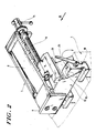
- the clamping device 5 (cf. in particular FIGS. 2 and 3) conventionally comprises a hollow clamping arm 8 with a stop plate 9 acting on the workpiece 6. Inside the clamping arm 8, a screw spindle 10 is rotatably and axially immovably mounted. The screw spindle 10 projects with its one end (located on the left in FIG. 1) beyond the clamping arm 8 and there has the usual, transversely displaceable actuating arm 11.
- the clamping arm 8 is mounted in a known manner on a clamping block 12 parallel to the axis of the screw 10 slidably, as best seen in FIGS. 2 and 4.
- the end of the screw spindle 10 opposite the actuating arm 11 engages in an internal thread 13 of the clamping block 12.
- the clamping arm 8 moves relative to the stationary clamping block 12 in order to clamp the workpiece 6 against a part of the machine frame 1 opposite the stop plate 9.
- the clamping block 12 is assigned two movable slot nuts 14, 15 which protrude into a profile slot 16 in the machine frame 1 which is complementary to the cross-sectional profile of these stones 14, 15.
- the sliding blocks 14 and 15 and the profile groove 16 can, as shown, have a T-profile, but they could also be provided with the usual dovetail or other cross-sectional profile.
- each sliding block 14, 15 has first inclined surfaces 17 and 18 which face one another and extend transversely to the profile groove 16 and which, for example, are inclined at 45 ° to the horizontal. With these first inclined surfaces 17, 18, the sliding blocks 14, 15 rest slidably on corresponding, second inclined surfaces 19, 20 of the clamping block 12.
- the clamping block 12 has a relatively wide bore 21 which runs transversely to the longitudinal axis of the screw spindle 10 and is freely traversed by a further screw spindle 22 such that the spindle 22 (in FIG. 4) is a certain distance (in the plane of the drawing) can move up and down.
- the Screw spindle 22 lies with a screwed-on and wedged extension 23 against the free end face of the sliding block 15 in such a way that the spindle 22 is rotatably supported on this sliding block 15 and axially (in FIG. 4 to the left) it is immovably supported.
- the screw spindle 22 can be rotated by means of a clamping lever 24 firmly connected to the screw spindle 22. With its end opposite the clamping lever 24, the screw spindle 22 engages in an internal thread 25 of the sliding block 14.
- the two sliding blocks 14, 15 mediate a clamping of the clamping device 5 in the profile groove 16 at two relatively remote locations.
- This clamping is more precise and can be carried out with greater force than in known arrangements, where only a single clamping sliding block approximately in the center of the clamping block 12 (FIG. 4) is provided, which is also displaced by an eccentric and not by inclined surfaces.
- the inclined surfaces 17, 18 and 19, 20 can be adjusted with their inclination so that a sensitive clamping with great force can be achieved.
- the screw spindle 22 runs parallel to the profile groove 16 and thus also transversely to the screw spindle 10.
- the clamping lever 24 is arranged in the region of an end face of the sliding block 15 extending transversely to the groove 16, that is to say laterally on the clamping block 12.
- the corresponding end face of the sliding block 14 opposite on the clamping block 12 is free, so that additional parts, for example a second clamping arm, can be arranged there.
Landscapes
- Engineering & Computer Science (AREA)
- Mechanical Engineering (AREA)
- Sawing (AREA)
- Finish Polishing, Edge Sharpening, And Grinding By Specific Grinding Devices (AREA)
Applications Claiming Priority (2)
| Application Number | Priority Date | Filing Date | Title |
|---|---|---|---|
| DE19863636050 DE3636050A1 (de) | 1986-10-23 | 1986-10-23 | Kreissaegemaschine |
| DE3636050 | 1986-10-23 |
Publications (1)
| Publication Number | Publication Date |
|---|---|
| EP0268096A1 true EP0268096A1 (fr) | 1988-05-25 |
Family
ID=6312297
Family Applications (1)
| Application Number | Title | Priority Date | Filing Date |
|---|---|---|---|
| EP87115385A Withdrawn EP0268096A1 (fr) | 1986-10-23 | 1987-10-21 | Machine à scier à lame circulaire |
Country Status (3)
| Country | Link |
|---|---|
| US (1) | US4815350A (fr) |
| EP (1) | EP0268096A1 (fr) |
| DE (1) | DE3636050A1 (fr) |
Cited By (3)
| Publication number | Priority date | Publication date | Assignee | Title |
|---|---|---|---|---|
| EP0445406A3 (en) * | 1990-03-09 | 1991-11-13 | Keuro Maschinenbau Gmbh & Co. Kg | Device for horizontally clamping workpieces to the table of a vertical saw |
| EP0614728A1 (fr) * | 1993-03-06 | 1994-09-14 | Handtmann A-Punkt Automation Gmbh | Etan |
| CN104400462A (zh) * | 2014-11-28 | 2015-03-11 | 重庆红旗缸盖制造有限公司 | 辅助支撑座 |
Families Citing this family (6)
| Publication number | Priority date | Publication date | Assignee | Title |
|---|---|---|---|---|
| JPH0516051U (ja) * | 1991-08-05 | 1993-03-02 | リヨービ株式会社 | 切断機のバイス装置 |
| US5239905A (en) * | 1992-10-19 | 1993-08-31 | Dunn Gail E | Miter table molding positioning apparatus |
| US5720096A (en) * | 1993-04-26 | 1998-02-24 | Black & Decker Inc. | Power tool with locking fence |
| US20050115376A1 (en) * | 1997-12-23 | 2005-06-02 | Industrial Solutions Llc | Jig for cut-off saw |
| US8601925B1 (en) * | 2011-07-01 | 2013-12-10 | Rangel Coto | Dental prosthesis mold shaping apparatus |
| CN103586709B (zh) * | 2013-11-01 | 2015-08-19 | 哈尔滨汽轮机厂有限责任公司 | 五轴数控机床汽道加工件的辅助装夹方法及辅助夹具 |
Citations (5)
| Publication number | Priority date | Publication date | Assignee | Title |
|---|---|---|---|---|
| DE855790C (de) * | 1950-04-27 | 1952-11-20 | Hahn & Kolb | Drehbank, vorzugsweise Revolverdrehbank, mit Spaeneauffangwanne |
| US2687188A (en) * | 1951-10-10 | 1954-08-24 | Genevoise Instr Physique | Arrangement for locking machine tool spindles |
| CH386208A (de) * | 1960-02-23 | 1964-12-31 | Chr Eisele Kg Maschinenfabrik | Metallkreissäge |
| DE3306743A1 (de) * | 1983-02-25 | 1984-08-30 | Chr. Eisele Maschinenfabrik GmbH & Co KG, 7316 Köngen | Kreissaegemaschine |
| US4494591A (en) * | 1983-09-14 | 1985-01-22 | Shopsmith, Inc. | Tilting table for a woodworking tool |
Family Cites Families (1)
| Publication number | Priority date | Publication date | Assignee | Title |
|---|---|---|---|---|
| US3971186A (en) * | 1975-08-13 | 1976-07-27 | Electronic Memories And Magnetics Corporation | Wedge lock unit |
-
1986
- 1986-10-23 DE DE19863636050 patent/DE3636050A1/de not_active Withdrawn
-
1987
- 1987-10-21 EP EP87115385A patent/EP0268096A1/fr not_active Withdrawn
- 1987-10-22 US US07/112,384 patent/US4815350A/en not_active Expired - Fee Related
Patent Citations (5)
| Publication number | Priority date | Publication date | Assignee | Title |
|---|---|---|---|---|
| DE855790C (de) * | 1950-04-27 | 1952-11-20 | Hahn & Kolb | Drehbank, vorzugsweise Revolverdrehbank, mit Spaeneauffangwanne |
| US2687188A (en) * | 1951-10-10 | 1954-08-24 | Genevoise Instr Physique | Arrangement for locking machine tool spindles |
| CH386208A (de) * | 1960-02-23 | 1964-12-31 | Chr Eisele Kg Maschinenfabrik | Metallkreissäge |
| DE3306743A1 (de) * | 1983-02-25 | 1984-08-30 | Chr. Eisele Maschinenfabrik GmbH & Co KG, 7316 Köngen | Kreissaegemaschine |
| US4494591A (en) * | 1983-09-14 | 1985-01-22 | Shopsmith, Inc. | Tilting table for a woodworking tool |
Cited By (3)
| Publication number | Priority date | Publication date | Assignee | Title |
|---|---|---|---|---|
| EP0445406A3 (en) * | 1990-03-09 | 1991-11-13 | Keuro Maschinenbau Gmbh & Co. Kg | Device for horizontally clamping workpieces to the table of a vertical saw |
| EP0614728A1 (fr) * | 1993-03-06 | 1994-09-14 | Handtmann A-Punkt Automation Gmbh | Etan |
| CN104400462A (zh) * | 2014-11-28 | 2015-03-11 | 重庆红旗缸盖制造有限公司 | 辅助支撑座 |
Also Published As
| Publication number | Publication date |
|---|---|
| DE3636050A1 (de) | 1988-04-28 |
| US4815350A (en) | 1989-03-28 |
Similar Documents
| Publication | Publication Date | Title |
|---|---|---|
| DE3501657A1 (de) | Vorrichtung zum vorritzen von werkstuecken | |
| DE3636050A1 (de) | Kreissaegemaschine | |
| DE1453213C3 (fr) | ||
| EP0994766B1 (fr) | Dispositif de butee pour scie a onglet | |
| DE4004705A1 (de) | Tischkreissaege | |
| CH441942A (de) | Bügelsägemaschine | |
| EP0430228A2 (fr) | Machine à percer | |
| DE4406034C2 (de) | Konturen-Seilsäge | |
| DE2951355A1 (de) | Rolltisch fuer holzbearbeitungsmaschinen | |
| EP0123028A1 (fr) | Machine à scier à lame circulaire | |
| DE3422101C2 (fr) | ||
| DE9207811U1 (de) | Gehrungsanschlag | |
| EP0727271B1 (fr) | Dispositif pour l'ajustement fine de la position latérale d'une lame de scie à inciser sur une scie circulaire | |
| DE3813852C2 (fr) | ||
| EP0118077B1 (fr) | Butée à onglets | |
| DE4337681C1 (de) | Verfahren und Vorrichtung zum Aussägen von im wesentlichen kreisförmigen Scheiben aus im wesentlichen plattenförmigem Material | |
| WO1990007405A1 (fr) | Machine d'enlevement de copeaux | |
| DE3344963C2 (fr) | ||
| DE9307670U1 (de) | Rolltischführung eines Rolltisches einer Werkzeugmaschine | |
| CH386208A (de) | Metallkreissäge | |
| DE9307673U1 (de) | Gehrungsanschlag für Werkzeugmaschinen | |
| DE10000102A1 (de) | Anschlagvorrichtung | |
| DE3733454A1 (de) | Gestell zur bearbeitung von kabelschaechten mit einer elektromotorisch betriebenen handstichsaege | |
| DD228986A3 (de) | Vorrichtung zur lageaenderung von bauelementen | |
| EP0293819B1 (fr) | Scie circulaire à froid dont la lame peut basculer pour se présenter par en-dessous dans la fente d'une table d'appui |
Legal Events
| Date | Code | Title | Description |
|---|---|---|---|
| PUAI | Public reference made under article 153(3) epc to a published international application that has entered the european phase |
Free format text: ORIGINAL CODE: 0009012 |
|
| AK | Designated contracting states |
Kind code of ref document: A1 Designated state(s): AT BE CH DE ES FR GB IT LI NL SE |
|
| 17P | Request for examination filed |
Effective date: 19881125 |
|
| 17Q | First examination report despatched |
Effective date: 19900228 |
|
| STAA | Information on the status of an ep patent application or granted ep patent |
Free format text: STATUS: THE APPLICATION HAS BEEN WITHDRAWN |
|
| 18W | Application withdrawn |
Withdrawal date: 19900627 |
|
| R18W | Application withdrawn (corrected) |
Effective date: 19900627 |
|
| RIN1 | Information on inventor provided before grant (corrected) |
Inventor name: FAIG, PAUL |