EP0268183A2 - Système de freinage de stationnement pour véhicules ferroviaires - Google Patents
Système de freinage de stationnement pour véhicules ferroviaires Download PDFInfo
- Publication number
- EP0268183A2 EP0268183A2 EP87116538A EP87116538A EP0268183A2 EP 0268183 A2 EP0268183 A2 EP 0268183A2 EP 87116538 A EP87116538 A EP 87116538A EP 87116538 A EP87116538 A EP 87116538A EP 0268183 A2 EP0268183 A2 EP 0268183A2
- Authority
- EP
- European Patent Office
- Prior art keywords
- handbrake
- brake
- pipe
- spring
- release
- Prior art date
- Legal status (The legal status is an assumption and is not a legal conclusion. Google has not performed a legal analysis and makes no representation as to the accuracy of the status listed.)
- Withdrawn
Links
Images


Classifications
-
- B—PERFORMING OPERATIONS; TRANSPORTING
- B61—RAILWAYS
- B61H—BRAKES OR OTHER RETARDING DEVICES SPECIALLY ADAPTED FOR RAIL VEHICLES; ARRANGEMENT OR DISPOSITION THEREOF IN RAIL VEHICLES
- B61H13/00—Actuating rail-vehicle brakes
- B61H13/02—Hand or other personal actuation
Definitions
- This invention relates to spring applied air pressure released parking brakes for railway vehicles, and it more particularly relates to parking brakes governed jointly by fluid spring handbrake cylinders as well as manual handbrake control devices. It has been proposed, as U.S. Patent No. 4,033,629, that a parking brake system having a spring applied and fluid pressure released handbrake cylinder be provided having a special reserve reservoir for providing release pressure to provide handbrake operation in the absence of pressure in the brake pipe. This special reservoir pressure must be carried above normal brake pipe pressure, requiring a special compressor to raise the pressure, and at times the attachment of an additional supply of fluid pressure to the system is required.
- a fluid brake control system for a railway vehicle having a brake pipe, control valve device, brake cylinder, and a brake rigging, and having means including the control valve device and brake cylinder for selectively controlling the brake rigging in accordance with variations in fluid pressure within the brake pipe, characterized by fluid pressure releaseable spring handbrake cylinder means for controlling the brake rigging, manually operable handbrake application and release means having an axially operable handbrake rod for controlling the brake rigging, the manually operable handbrake application and release means having locking means for at times locking the handbrake rod against axial movement in one direction, said locking means including toggle means having reset and release positions for normally locking the handbrake rod in a reset position wherein brakes of the brake rigging can be applied or released by fluid pressure in the spring handbrake cylinder, and linkage means having a fulcrum point connection to said handbrake rod for connecting the spring handbrake cylinder and the handbrake rod to the brake cylinder for operating the brake rigging by
- a protective device for charging a handbrake release pipe from a brake pipe characterized by brake pipe, auxiliary reservoir and handbrake release pipe ports, cut-off, charging and exhaust pistons, a charging passage extending from the brake pipe port to the handbrake pipe port including a charging check valve and a chamber at one side of the cut-off piston, the charging passage also being connected to a chamber above the exhaust piston and below the charging piston, and graduating spring means biasing the respective pistons in opposition to fluid pressure in the chambers adjoining the respecting pistons.
- a manual handbrake mechanism adapted to selectively govern utilization of a spring handbrake cylinder to control brakes of a brake rigging, characterized by a handbrake mechanism housing, a handbrake rod journalled in the housing for axial movement to first and second axially operated positions, locking means in the housing for selectively limiting axial movement of the handbrake rod in a particular direction, said locking means including a toggle that is normally in a reset locking position restraining the handbrake rod against axial movement in a particular direction, and a manual handbrake handle for selectively governing the locking means.
- a conventional fluid brake control system for a railway vehicle having a brake pipe, control valve device, and a brake cylinder for selectively governing the application of force to the brakes of a brake rigging in accordance with fluid pressure in the brake pipe.
- Additional apparatus for parking brake control is provided including a handbrake release pipe, a protective device, a fluid pressure releaseable spring handbrake cylinder, and a mechanical manual handbrake device for selectively controlling the force applied to brakes of a brake rigging, irrespective of whether fluid pressure is available for use in releasing the brakes.
- linkage means connecting the manual handbrake control apparatus to the brake cylinder having a moveable fulcrum that is applied on a handbrake rod for connecting the handbrake spring brake cylinder and the handbrake rod to the brake cylinder for operating the brake rigging by either the spring brake cylinder or the manual handbrake rod independently.
- a fluid brake control system is illustrated as having a conventional brake pipe 10, a control valve device 11, a brake cylinder 12 and a brake rigging 13, all of which are operable in response to changes in fluid pressure in the brake pipe 10 according to usual practice, and as disclosed, for example, in U.S. Patents Nos. 3,175,869 and 4,060,152.
- a handbrake control system including a train, or handbrake pipe 14, a protective device 15, a fluid pressure releaseable spring handbrake cylinder 16 and a manually operable handbrake mechanism having toggle type locking apparatus 18 (see Fig. 2), all of which is operable through linkage 19 to selectively operate the brake cylinder 12 for applying brakes to the vehicle through operation of the brake rigging 13.
- the linkage 19 comprises a brake link 20 that is connected at its mid-point by a clevis pin 21 fastening a clevis 22 on a manual handbrake rod 23.
- the lower end of the brake link 20 is connected by a pin 24 to a spring handbrake rod 25, and the upper end of the brake link 20 is connected by a link 26 to a lower arm of a bell crank 27, the upper arm of which being connected through a link 28 to cables 29, which are connected to the piston (not shown) of brake cylinder 12 to actuate the brake rigging 13 to a brake application position by the rotation of the bell crank 27 in a clockwise direction for pulling on the cables 29.
- the protection device 15 is illustrated as comprising a diaphragm operated vent valve 30 that is continually comparing the fluid pressure in the train or handbrake pipe 14 over line 31 with the force of a graduating spring 32 in the valve 30 so as to insure that a sufficient pressure is applied from the train pipe 14 over a passage 33 to a chamber 34 for compressing spring 35 to maintain the handbrake control system in a normal released position.
- the protective device 15 also has a vent valve 36 that is controlled over line 37 by a pilot vent valve 38 in the manual handbrake mechanism 17.
- the pilot valve 38 is actuated at point 38a to vent the train pipe 14 by movement of a handle 39 from its normal stow position, in which it is biased by springs 39a and 39b of Fig. 1A, to an application position.
- the vent valve 38 can be actuated, for example, by a spring biased shaft depressed at 38a by movement of the lever 39.
- a modified form of the invention is applied to a single brake pipe braking system for connection throughout a train, while a local handbrake supply pipe 45 is used for each vehicle to supply fluid for the handbrakes of the various trucks of each car having separately controlled handbrakes.
- fluid pressure for the handbrake supply pipe 45 is obtained from the brake pipe 10 by a modified protective device 46 having ports connected over lines 47, 48 and 49 to the brake pipe 10, an auxiliary reservoir 50 and supply pipe 45 respectively.
- the protective device 46 comprises a charging check valve 51, a charging piston 52, a cut-off piston 53, and an exhaust piston 54.
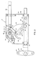
- the manual handbrake mechanism 17 comprises a housing 60 having a cover 61 for journalling the manual handbrake rod 23 and housing a sector gear 62 journalled by a journal pin 63 and driven manually by ratcheting a pinion gear 64.
- the gear 24 is driven by a ratchet wheel 65, both of which are secured on a shaft 66.
- the ratchet wheel has associated therewith a holding pawl 67 pivoted on a retaining plate at a point 69.
- the holding pawl 67 is biased against the ratchet wheel 65 by a spring 70.
- a driving pawl 71 is operably connected by pin 72 to the manually operable handle 39.
- a strike plate 73 coordinates operation of the driving pawl 71 and the holding pawl 67 and is preferably adjusted to release both the driving pawl 71 and the holding pawl 67 from engagement of the ratchet wheel 65 when the lever 32 is in a stow position in which it is biased by springs 39a and 39b of Fig. 1A.
- the toggle locking mechanism 18 comprises laterally spaced over center links 75 and 76 pivotally secured at one end to the manual handbrake rod 23 by a hinge pin 77.
- the over center links 75 and 76 are journalled on a pin 78 operably connecting their other ends to an off center point 78 on the opposite sides respectively of the sector gear 62.
- the toggle mechanism 18 is shown in its reset position wherein the links 75 and 76 are in an over center position wherein the longitudinal center line 79 dips below a center line between the journal pin 63 of the sector gear and the hinge pin 77.
- the spring handbrake cylinder 16, which is connected at 24 can selectively apply and release the brakes of the brake rigging 13 without requiring operation of the manual handbrake rod 23, the rod 23 being locked against movement to the left by the toggle mechanism 18.
- a toggle spring 80 helps in positive operation of the toggle 18 to its locking and unlocking positions. The spring 80 is stretched between a pin 81 in the manual handbrake rod 23 and a pin 82 in the sector gear 23, which in turn operates in an annular slot 83 in the cover plate 61.
- the operation of the system, according to Fig. 1, as governed by the brake pipe 10, is according to usual practice wherein the control valve 11 and the auxiliary and emergency reservoirs 50 and 55 provide control for a conventional brake cylinder 12, which in turn operates the brakes of a brake rigging 13 in the usual manner.
- the train pipe 14 is normally pressurized to maintain all of the spring handbrake cylinders 16 that are connected thereto in released positions, and the handbrakes are not normally applied unless initiated manually by operation of a manual handbrake unit 17, which must generally take place when the train is stopped.
- the pilot valve 38 is actuated to exhaust air over passage 37, and it in turn causes actuation of the vent valve 36 in protective device 15, which causes exhaust of fluid pressure in the train pipe 14 over passage 31. This also vents air from the brake pipe over passage 32a, but if the train is stopped, the air is generally vented from the brake pipe 10 at this time anyway.
- the brake thus applied can be released, either by supplying air to the spring handbrake cylinders 16 through the train pipe 14, or by operating the levers 39 of similar devices 17 to their release positions.
- the brakes will be released because air will compress the spring 35 within the spring handbrake cylinder 16, while in the second case, the brakes will be released because a fulcrum point 21 in each case is allowed to move to the left, thus allowing the spring brake cylinder 16 to go to full travel of the spring 35 for releasing the brakes of the brake rigging 13.
- the protection valves 15 serve to prevent application of brakes by the spring handbrake cylinders 16 without knowledge of the train operators. In operation, this device senses the pressure in the chamber 34 of the spring handbrake cylinder 16, and if this pressure is below a pressure for maintaining the brakes released, which may be 40 lbs. pressure, for example, the protection device 15 vents the brake pipe 10 to atmosphere, causing the brakes on the entire train to apply in emergency. This prevents the dangerous condition of the dragging of a single spring applied handbrake for a long distance on an otherwise released train.
- ratcheting the handle 39 between the stow and apply positions causes the application of a previously released spring brake by retracting the fulcrum point 21 in the direction of the housing of the manual handbrake mechanism 17, thus permitting the handbrake spring 35 to actuate the brake rigging 13 to an application position by rotation of brake link 20 in a clockwise direction when fulcrum point 21 is moved to the right.
- the operators action with or without fluid pressure in the train pipe 14 is always the same, to move the operating handle 39 to the application position.
- FIG. 4 operation will now be considered of the modification to require only a single continuous brake pipe 10 extending throughout the train.
- This form is modified from Fig. 1 primarily in a protective device 46 in that an additional piston 52 operates to permit charging of supply pipe 45 when brake pipe pressure is below 55 psi as long as the brake pipe 10 is being charged.
- This charging take place in the protective device 46 from the brake pipe 10 over passage 48, passage 91, through an open passage 92 in a spool valve 93, charging check valve 51, passage 96, to a chamber 97 over a cut-off piston 53, and over passage 49 to a supply pipe 45.
- Brake pipe fluid pressure is also applied from passage 96 through passage 99 to a chamber 100 above an exhaust piston 54.
- This charging of the supply pipe 45 is accomplished only if the exhaust valve 102 can be held closed by a 10 lb. spring 103 in piston 52 to hold valve 102 closed subsequently until supply pressure builds up over 55 lbs. by a pressure differential between brake pipe pressure in chamber 100 and auxiliary reservoir pressure of reservoir 50 that is applied over passages 48 and 104 to chamber 105 beneath piston 54.
- a 1 lb. spring under piston 101 assures that the vent valve 102 will remain closed until brake pipe pressure in chamber 97 is above 55 lbs. as long as brake pipe pressure is increasing to hold the vent valve 102 closed because of being higher pressure than the force of a 55 lb. spring 107 beneath the charging piston 53.
- the mechanism as illustrated can be said to be in a reset position as shown, with the manual handbrake rod 23 retracted to the right and locked against movement to the left by the toggle mechanism 18. From this position of the fulcrum pin 21, the spring handbrake cylinder 16 rotates the brake link 20 clockwise for brake application and counter clockwise for brake release (see Fig. 1).
- handbrake application must be initiated by actuating a handbrake lever 39 from its normal stow to an application position.
- the handle 39 is biased by springs 39a and 39b (see Fig. 1A) to be restored to the stow position in which it is shown when released by an operator. In the stow position both pawls 67 and 71 are released from the ratchet wheel 65.
- a manual lever 39 is moved to an application position, which in Fig. 2 is upwardly, but in Fig. 1, the mechanism 17 is disposed in the opposite direction, and movement of lever 39 is downwardly from its stow position for handbrake application.
- This actuates the pilot vent valve 38 of Fig. 1 as has been described to vent the handbrake release train pipe 14 and cause springs 35 to expand in their cylinders 16 and apply the brakes of riggings 13 by clockwise rotation of the brake links 20.
- the reverse operation is effective upon restoration of fluid pressure to the train pipe 14 to release the handbrakes.
- the distance of travel for rod 23 under these conditions is selected to be sufficient for the release of brakes of the brake rigging 13, which by using slack adjusters, may be about 4 inches, and which is obtained by rotation of bell crank 19 in a clockwise direction by extension of the rod 23 to the left.
- the toggle spring 80 snaps pin 82 in its groove 83 into its released position, with the sector gear 62 rotated counter clockwise.
- pressurization of cylinders 16 Upon restoration of fluid pressure to the train line 14, after brakes have been manually released without fluid pressure as described above, pressurization of cylinders 16 resets any of the manual mechanism 17 that have been operated to this release position by actuating rods 23 to the right to rotate the gear sectors 62 clockwise to cause springs 80 (see Fig. 2) to snap the toggle mechanism 18 into their locked positions, and thus restore the system to its normal positions.
Landscapes
- Engineering & Computer Science (AREA)
- Mechanical Engineering (AREA)
- Braking Systems And Boosters (AREA)
Applications Claiming Priority (2)
| Application Number | Priority Date | Filing Date | Title |
|---|---|---|---|
| US06/932,418 US4746171A (en) | 1986-11-19 | 1986-11-19 | Parking brake system for railway vehicles |
| US932418 | 1986-11-19 |
Publications (2)
| Publication Number | Publication Date |
|---|---|
| EP0268183A2 true EP0268183A2 (fr) | 1988-05-25 |
| EP0268183A3 EP0268183A3 (fr) | 1990-05-02 |
Family
ID=25462272
Family Applications (1)
| Application Number | Title | Priority Date | Filing Date |
|---|---|---|---|
| EP87116538A Withdrawn EP0268183A3 (fr) | 1986-11-19 | 1987-11-09 | Système de freinage de stationnement pour véhicules ferroviaires |
Country Status (6)
| Country | Link |
|---|---|
| US (1) | US4746171A (fr) |
| EP (1) | EP0268183A3 (fr) |
| AU (1) | AU594195B2 (fr) |
| CA (1) | CA1289484C (fr) |
| MX (1) | MX160855A (fr) |
| ZA (1) | ZA877009B (fr) |
Cited By (5)
| Publication number | Priority date | Publication date | Assignee | Title |
|---|---|---|---|---|
| FR2644419A1 (fr) * | 1988-11-14 | 1990-09-21 | Westinghouse Brake & Signal | Ensemble de freinage ferroviaire |
| CN102490760A (zh) * | 2011-11-29 | 2012-06-13 | 南车株洲电力机车有限公司 | 一种用于停放制动装置的手缓解辅助装置 |
| WO2016018215A1 (fr) * | 2014-07-28 | 2016-02-04 | New York Air Brake, LLC | Système de commande pour frein de stationnement de véhicule ferroviaire |
| US9393945B2 (en) | 2014-07-28 | 2016-07-19 | New York Air Brake, LLC | Control system for rail car parking brake |
| EP1516791B1 (fr) * | 2003-09-15 | 2017-08-09 | CNH Industrial Italia S.p.A. | Frein de stationnement pour véhicule, notamment tracteur |
Families Citing this family (17)
| Publication number | Priority date | Publication date | Assignee | Title |
|---|---|---|---|---|
| US4978178A (en) * | 1989-06-09 | 1990-12-18 | General Signal Corporation | Automatic self-resetting parking brake |
| US5469941A (en) * | 1994-02-07 | 1995-11-28 | James T. Williamson | Automatic handbrake release system for a railroad car |
| US5738416A (en) * | 1994-07-22 | 1998-04-14 | Westinghouse Air Brake Company | Railway braking apparatus to effect a change in a handbrake |
| RU2129502C1 (ru) * | 1996-07-22 | 1999-04-27 | Акционерное общество открытого типа "Тверской вагоностроительный завод" | Автоматический стояночный тормоз железнодорожного подвижного состава |
| US6491352B2 (en) * | 1999-02-22 | 2002-12-10 | Westinghouse Air Brake Technologies Corporation | Spring applied parking brake for rail cars |
| WO2001074638A1 (fr) * | 2000-04-04 | 2001-10-11 | Utd, Inc. | Systeme de freins et procede correspondant |
| US6375278B1 (en) | 2000-12-20 | 2002-04-23 | New York Air Brake Corporation | Hydraulic parking brake |
| US7306295B2 (en) * | 2003-03-05 | 2007-12-11 | New York Air Brake Corporation | Pump system for parking brakes for a rail vehicle |
| US6854570B2 (en) | 2003-05-14 | 2005-02-15 | Westinghouse Air Brake Technologies Corporation | Brake cylinder parking brake system |
| US7140477B2 (en) * | 2003-09-09 | 2006-11-28 | Wabtec Holding Corp. | Automatic parking brake for a rail vehicle |
| US7404473B2 (en) * | 2003-09-09 | 2008-07-29 | Wabtec Holding Corp. | Automatic parking brake for a rail vehicle |
| US6994191B2 (en) * | 2003-11-04 | 2006-02-07 | Arvinmeritor Technology, Llc | Pneumatically actuated parking brake |
| US9623855B2 (en) * | 2004-01-08 | 2017-04-18 | New York Air Brake Llc | Parking brake system including a brake cylinder |
| US7249659B2 (en) * | 2004-01-08 | 2007-07-31 | New York Air Brake Corporation | Fluid actuator |
| US7121634B2 (en) * | 2004-06-09 | 2006-10-17 | Arvinmeritor Technology, Llc | Pneumatically actuated parking brake |
| US9725080B1 (en) * | 2009-01-23 | 2017-08-08 | New York Air Brake Corporation | Parking brake system for locomotive |
| CN106364523A (zh) * | 2016-10-21 | 2017-02-01 | 中车青岛四方车辆研究所有限公司 | 机车停放制动机构的缓解辅助装置 |
Family Cites Families (14)
| Publication number | Priority date | Publication date | Assignee | Title |
|---|---|---|---|---|
| US3175869A (en) * | 1961-07-21 | 1965-03-30 | Westinghouse Air Brake Co | Fluid pressure brake control apparatus with accelerated release after service application |
| US3272566A (en) * | 1963-12-30 | 1966-09-13 | James H Clack | Combined service and emergency brake system apparatus |
| US3276551A (en) * | 1964-05-18 | 1966-10-04 | Charles C Buletti | Vehicle emergency brake |
| US3394779A (en) * | 1966-03-21 | 1968-07-30 | Graubremse Gmbh | Pressure operated braking device for vehicles |
| FR1506522A (fr) * | 1966-11-08 | 1967-12-22 | Saviem | Frein à ressort perfectionné |
| US3508794A (en) * | 1968-05-06 | 1970-04-28 | Gen Signal Corp | Hydraulic brake circuits |
| GB1285158A (en) * | 1970-05-05 | 1972-08-09 | Dba Sa | Manual release mechanism for emergency and parking brake systems |
| US3746403A (en) * | 1971-10-04 | 1973-07-17 | Abex Corp | Hydraulic brakes |
| US4060152A (en) * | 1975-06-24 | 1977-11-29 | General Signal Corporation | Rail car brake apparatus |
| US4033629A (en) * | 1976-06-09 | 1977-07-05 | Westinghouse Air Brake Company | Automatic freight car brake apparatus with spring-applied fluid-pressure-released hand brake |
| SE402081B (sv) * | 1976-10-11 | 1978-06-19 | Bromsregulator Svenska Ab | Anordning med reglerventil for att uppheva och ateruppretta arbetsfunktionen hos en fjederbromsaktuator |
| DE2708629A1 (de) * | 1977-02-28 | 1978-08-31 | Knorr Bremse Gmbh | Druckmittelbremseinrichtung, insbesondere fuer schienenfahrzeuge |
| US4236424A (en) * | 1979-02-08 | 1980-12-02 | American Standard Inc. | Hand brake for railway vehicles |
| US4279332A (en) * | 1979-10-01 | 1981-07-21 | American Standard Inc. | Manual release mechanism for spring-applied parking brake |
-
1986
- 1986-11-19 US US06/932,418 patent/US4746171A/en not_active Expired - Lifetime
-
1987
- 1987-09-17 ZA ZA877009A patent/ZA877009B/xx unknown
- 1987-09-23 AU AU78905/87A patent/AU594195B2/en not_active Expired
- 1987-10-28 CA CA000550471A patent/CA1289484C/fr not_active Expired - Lifetime
- 1987-11-09 EP EP87116538A patent/EP0268183A3/fr not_active Withdrawn
- 1987-11-19 MX MX9426A patent/MX160855A/es unknown
Cited By (8)
| Publication number | Priority date | Publication date | Assignee | Title |
|---|---|---|---|---|
| FR2644419A1 (fr) * | 1988-11-14 | 1990-09-21 | Westinghouse Brake & Signal | Ensemble de freinage ferroviaire |
| EP1516791B1 (fr) * | 2003-09-15 | 2017-08-09 | CNH Industrial Italia S.p.A. | Frein de stationnement pour véhicule, notamment tracteur |
| CN102490760A (zh) * | 2011-11-29 | 2012-06-13 | 南车株洲电力机车有限公司 | 一种用于停放制动装置的手缓解辅助装置 |
| CN102490760B (zh) * | 2011-11-29 | 2015-02-25 | 南车株洲电力机车有限公司 | 一种用于停放制动装置的手缓解辅助装置 |
| WO2016018215A1 (fr) * | 2014-07-28 | 2016-02-04 | New York Air Brake, LLC | Système de commande pour frein de stationnement de véhicule ferroviaire |
| US9393945B2 (en) | 2014-07-28 | 2016-07-19 | New York Air Brake, LLC | Control system for rail car parking brake |
| CN106536308A (zh) * | 2014-07-28 | 2017-03-22 | 纽约气闸有限公司 | 用于轨道车停车制动器的控制系统 |
| CN106536308B (zh) * | 2014-07-28 | 2019-03-26 | 纽约气闸有限公司 | 用于轨道车停车制动器的控制系统 |
Also Published As
| Publication number | Publication date |
|---|---|
| US4746171A (en) | 1988-05-24 |
| ZA877009B (en) | 1988-03-23 |
| EP0268183A3 (fr) | 1990-05-02 |
| AU594195B2 (en) | 1990-03-01 |
| CA1289484C (fr) | 1991-09-24 |
| AU7890587A (en) | 1988-06-09 |
| MX160855A (es) | 1990-06-05 |
Similar Documents
| Publication | Publication Date | Title |
|---|---|---|
| US4746171A (en) | Parking brake system for railway vehicles | |
| US4978178A (en) | Automatic self-resetting parking brake | |
| EP2109560B1 (fr) | Ensemble de frein de stationnement pour système de frein de véhicule ferroviaire | |
| US4874065A (en) | Parking brake system for railway vehicles | |
| EP1127766B1 (fr) | Actuateur de frein de stationnement à ressort | |
| CA2188107C (fr) | Frein de stationnement a commande pneumatique pour vehicule ferroviaire | |
| US6854570B2 (en) | Brake cylinder parking brake system | |
| US3999075A (en) | Control system for an integral spring-loaded parking and service brake | |
| US4799741A (en) | Parking brake system for railway vehicles | |
| US7404473B2 (en) | Automatic parking brake for a rail vehicle | |
| US4844554A (en) | Empty-load valve device | |
| US5469941A (en) | Automatic handbrake release system for a railroad car | |
| US3891277A (en) | Hand brake automatic release assembly | |
| US2121366A (en) | Braking mechanism | |
| US20030034689A1 (en) | Automatic set and release hand brake pneumatic circuit design II/automatic application function | |
| AU2020202656B2 (en) | Brake cylinder with parking brake mechanism | |
| US4368928A (en) | Inertial hand brake release apparatus | |
| US5201890A (en) | Railroad car handbrake release system | |
| US2945571A (en) | Automatic vehicle hand brake release | |
| US7048095B1 (en) | Hydraulically actuated parking brake | |
| CA2403695C (fr) | Conception de circuit pneumatique de serrage et de desserrage automatique de frein a main ii/fonction d'application automatique | |
| US1837466A (en) | Safety car control equipment | |
| EP1526056A1 (fr) | Frein à main à serrage et desserrage automatique pour circuit pneumatique design II/fonction d'application automatique |
Legal Events
| Date | Code | Title | Description |
|---|---|---|---|
| PUAI | Public reference made under article 153(3) epc to a published international application that has entered the european phase |
Free format text: ORIGINAL CODE: 0009012 |
|
| AK | Designated contracting states |
Kind code of ref document: A2 Designated state(s): DE FR GB |
|
| PUAL | Search report despatched |
Free format text: ORIGINAL CODE: 0009013 |
|
| AK | Designated contracting states |
Kind code of ref document: A3 Designated state(s): DE FR GB |
|
| 17P | Request for examination filed |
Effective date: 19900823 |
|
| RAP1 | Party data changed (applicant data changed or rights of an application transferred) |
Owner name: KNORR BRAKE HOLDING CORPORATION |
|
| 17Q | First examination report despatched |
Effective date: 19930217 |
|
| STAA | Information on the status of an ep patent application or granted ep patent |
Free format text: STATUS: THE APPLICATION IS DEEMED TO BE WITHDRAWN |
|
| 18D | Application deemed to be withdrawn |
Effective date: 19930828 |
|
| RIN1 | Information on inventor provided before grant (corrected) |
Inventor name: ENGLE, THOMAS H. |