EP0268244A2 - Dispositif de sécurité - Google Patents
Dispositif de sécurité Download PDFInfo
- Publication number
- EP0268244A2 EP0268244A2 EP87116884A EP87116884A EP0268244A2 EP 0268244 A2 EP0268244 A2 EP 0268244A2 EP 87116884 A EP87116884 A EP 87116884A EP 87116884 A EP87116884 A EP 87116884A EP 0268244 A2 EP0268244 A2 EP 0268244A2
- Authority
- EP
- European Patent Office
- Prior art keywords
- operator
- supply line
- sensor
- relief
- actuation sensor
- Prior art date
- Legal status (The legal status is an assumption and is not a legal conclusion. Google has not performed a legal analysis and makes no representation as to the accuracy of the status listed.)
- Granted
Links
- 230000001681 protective effect Effects 0.000 claims abstract description 12
- RYGMFSIKBFXOCR-UHFFFAOYSA-N Copper Chemical compound [Cu] RYGMFSIKBFXOCR-UHFFFAOYSA-N 0.000 claims description 3
- 229910052782 aluminium Inorganic materials 0.000 claims description 3
- XAGFODPZIPBFFR-UHFFFAOYSA-N aluminium Chemical compound [Al] XAGFODPZIPBFFR-UHFFFAOYSA-N 0.000 claims description 3
- 229910052802 copper Inorganic materials 0.000 claims description 3
- 239000010949 copper Substances 0.000 claims description 3
- 210000003811 finger Anatomy 0.000 claims description 3
- 230000035699 permeability Effects 0.000 claims description 3
- 210000003813 thumb Anatomy 0.000 claims description 3
- 239000011888 foil Substances 0.000 claims description 2
- 239000000696 magnetic material Substances 0.000 claims description 2
- 230000006698 induction Effects 0.000 claims 1
- 238000005516 engineering process Methods 0.000 abstract description 5
- 238000005422 blasting Methods 0.000 description 31
- 230000029058 respiratory gaseous exchange Effects 0.000 description 6
- 239000003795 chemical substances by application Substances 0.000 description 4
- 230000000694 effects Effects 0.000 description 4
- 241000282414 Homo sapiens Species 0.000 description 3
- 238000010276 construction Methods 0.000 description 3
- 230000010354 integration Effects 0.000 description 3
- 238000005270 abrasive blasting Methods 0.000 description 2
- 239000006260 foam Substances 0.000 description 2
- 230000001939 inductive effect Effects 0.000 description 2
- 229910052751 metal Inorganic materials 0.000 description 2
- 239000002184 metal Substances 0.000 description 2
- 230000004044 response Effects 0.000 description 2
- 239000004065 semiconductor Substances 0.000 description 2
- 239000007921 spray Substances 0.000 description 2
- 238000003860 storage Methods 0.000 description 2
- 229910000831 Steel Inorganic materials 0.000 description 1
- HCHKCACWOHOZIP-UHFFFAOYSA-N Zinc Chemical compound [Zn] HCHKCACWOHOZIP-UHFFFAOYSA-N 0.000 description 1
- 230000009471 action Effects 0.000 description 1
- 230000006978 adaptation Effects 0.000 description 1
- 239000000654 additive Substances 0.000 description 1
- 230000000996 additive effect Effects 0.000 description 1
- 230000008901 benefit Effects 0.000 description 1
- 230000008859 change Effects 0.000 description 1
- 230000006835 compression Effects 0.000 description 1
- 238000007906 compression Methods 0.000 description 1
- 210000003608 fece Anatomy 0.000 description 1
- 238000000227 grinding Methods 0.000 description 1
- 230000003993 interaction Effects 0.000 description 1
- 239000000463 material Substances 0.000 description 1
- 238000005259 measurement Methods 0.000 description 1
- 238000001465 metallisation Methods 0.000 description 1
- 150000002739 metals Chemical class 0.000 description 1
- 238000000034 method Methods 0.000 description 1
- 238000003801 milling Methods 0.000 description 1
- 230000003287 optical effect Effects 0.000 description 1
- 238000010422 painting Methods 0.000 description 1
- 230000000241 respiratory effect Effects 0.000 description 1
- 230000008054 signal transmission Effects 0.000 description 1
- 239000010959 steel Substances 0.000 description 1
- 238000009423 ventilation Methods 0.000 description 1
- XLYOFNOQVPJJNP-UHFFFAOYSA-N water Substances O XLYOFNOQVPJJNP-UHFFFAOYSA-N 0.000 description 1
- 238000003466 welding Methods 0.000 description 1
- 210000000707 wrist Anatomy 0.000 description 1
- 229910052725 zinc Inorganic materials 0.000 description 1
- 239000011701 zinc Substances 0.000 description 1
Images



Classifications
-
- B—PERFORMING OPERATIONS; TRANSPORTING
- B24—GRINDING; POLISHING
- B24C—ABRASIVE OR RELATED BLASTING WITH PARTICULATE MATERIAL
- B24C7/00—Equipment for feeding abrasive material; Controlling the flowability, constitution, or other physical characteristics of abrasive blasts
-
- B—PERFORMING OPERATIONS; TRANSPORTING
- B24—GRINDING; POLISHING
- B24C—ABRASIVE OR RELATED BLASTING WITH PARTICULATE MATERIAL
- B24C5/00—Devices or accessories for generating abrasive blasts
- B24C5/02—Blast guns, e.g. for generating high velocity abrasive fluid jets for cutting materials
-
- F—MECHANICAL ENGINEERING; LIGHTING; HEATING; WEAPONS; BLASTING
- F16—ENGINEERING ELEMENTS AND UNITS; GENERAL MEASURES FOR PRODUCING AND MAINTAINING EFFECTIVE FUNCTIONING OF MACHINES OR INSTALLATIONS; THERMAL INSULATION IN GENERAL
- F16P—SAFETY DEVICES IN GENERAL; SAFETY DEVICES FOR PRESSES
- F16P3/00—Safety devices acting in conjunction with the control or operation of a machine; Control arrangements requiring the simultaneous use of two or more parts of the body
- F16P3/12—Safety devices acting in conjunction with the control or operation of a machine; Control arrangements requiring the simultaneous use of two or more parts of the body with means, e.g. feelers, which in case of the presence of a body part of a person in or near the danger zone influence the control or operation of the machine
-
- H—ELECTRICITY
- H03—ELECTRONIC CIRCUITRY
- H03K—PULSE TECHNIQUE
- H03K17/00—Electronic switching or gating, i.e. not by contact-making and –breaking
- H03K17/94—Electronic switching or gating, i.e. not by contact-making and –breaking characterised by the way in which the control signals are generated
-
- H—ELECTRICITY
- H01—ELECTRIC ELEMENTS
- H01H—ELECTRIC SWITCHES; RELAYS; SELECTORS; EMERGENCY PROTECTIVE DEVICES
- H01H9/00—Details of switching devices, not covered by groups H01H1/00 - H01H7/00
- H01H9/02—Bases, casings, or covers
- H01H9/0214—Hand-held casings
- H01H2009/0221—Hand-held casings the switches being fixed to the operator's hand, e.g. integrated in a glove or fixed to a ring
-
- H—ELECTRICITY
- H01—ELECTRIC ELEMENTS
- H01H—ELECTRIC SWITCHES; RELAYS; SELECTORS; EMERGENCY PROTECTIVE DEVICES
- H01H2223/00—Casings
- H01H2223/04—Casings portable; hand held
-
- H—ELECTRICITY
- H01—ELECTRIC ELEMENTS
- H01H—ELECTRIC SWITCHES; RELAYS; SELECTORS; EMERGENCY PROTECTIVE DEVICES
- H01H2300/00—Orthogonal indexing scheme relating to electric switches, relays, selectors or emergency protective devices covered by H01H
- H01H2300/026—Application dead man switch: power must be interrupted on release of operating member
-
- Y—GENERAL TAGGING OF NEW TECHNOLOGICAL DEVELOPMENTS; GENERAL TAGGING OF CROSS-SECTIONAL TECHNOLOGIES SPANNING OVER SEVERAL SECTIONS OF THE IPC; TECHNICAL SUBJECTS COVERED BY FORMER USPC CROSS-REFERENCE ART COLLECTIONS [XRACs] AND DIGESTS
- Y10—TECHNICAL SUBJECTS COVERED BY FORMER USPC
- Y10S—TECHNICAL SUBJECTS COVERED BY FORMER USPC CROSS-REFERENCE ART COLLECTIONS [XRACs] AND DIGESTS
- Y10S200/00—Electricity: circuit makers and breakers
- Y10S200/02—Body attached switches
Definitions
- the invention relates to a safety device according to the preamble of claim 1.
- a safety device of the type in question is recommended for all types of devices to be handled by an operator, in order to protect an operator against accidents or to avoid an uncontrolled function of the device to be handled by the operator.
- a safety device is, for example, for a grinding machine operated by an operator. Milling machine or the like is just as recommendable as for a water extinguisher or foam extinguisher of a fire-fighting system, a welding torch, a spray head for painting work or spray metallization, etc.
- Such a safety device is particularly important for a blasting device of a blasting system for pressure medium blasting - dry blasting, wet blasting, wet blasting - where such a safety device, which acts as a dead man's switch, is required by safety regulations. Without this being intended to express a restriction for the area of application of a safety device of the type in question, this safety device is explained below primarily on the basis of the example of a blasting device of a blasting system.
- a known safety device for a device to be handled by an operator (DE-U 86 13 771) which is intended and suitable in particular for a blasting device of a blasting system, in which the device to be handled by the operator via a supply line for a supply means, there compressed air , is connected to a supply source
- the function of the device is controlled from the supply source.
- a control device is provided on the supply means source with which the supply of supply means can be controlled.
- the control device is influenced by an actuation sensor which is arranged on a handle of the device.
- the actuation sensor is connected to the control device via a cable dung. If the operator no longer influences the actuation sensor, the device is switched off.
- the actuation sensor of the known safety device is designed as an electronic, preferably contactlessly actuable, preferably only by a special influencing element, in particular a film that can be influenced.
- the device is also assigned a normal actuation unit for remote control of the device. This normal operating unit has a plurality of operating elements for different functions.
- a relief device for the supply line is also provided in the known safety device explained above.
- This relief device is arranged at a point on the supply line remote from the device near the connection of the supply line to the supply means source and has a relief cross section which roughly corresponds to the flow cross section of the supply line.
- the relief device is assigned a shut-off device for the supply line, the two devices being interlocked in terms of circuitry.
- the actuation sensor is considerably more difficult to bridge than, for example, a mechanical hand lever of a dead man's switch or the like. Nevertheless, a bridge is not impossible.
- the rear relief of the supply line which is essential for safety reasons, is effective in its effect, but is complex in terms of construction and wear, particularly when using highly abrasive blasting media in a blasting media line.
- the invention has for its object to improve the known safety device so that a bridging of the actuation sensor practically table is impossible and in the event of a response the supply line is optimally switched off.
- the above-stated object is achieved by the features of the characterizing part of claim 1. Due to the fact that the actuation sensor is attached to the hand of the operator, a bridging of the safety device or the actuation sensor is not possible at all, since the device itself is only passive. Without the actuation sensor assigned to the hand of the operator, a function of the device is systematically excluded.
- the above-mentioned object is further achieved by the features of the characterizing part of claim 9.
- the design of the relief device and / or the shut-off device as pinch devices is particularly simple and robust and has an optimal adaptation to the technical requirements, also and in particular when using highly abrasive blasting media as a result.
- the blasting system shown in FIG. 1 shows a compressed air line 1 which is connected to a supply medium source 3, here in the form of a conventional blasting medium storage container.
- a supply line 7 leads from a connecting device of the blasting agent storage container 3 to a device 8 which can be handled by an operator 30.
- the supply line 7 is a compressed air / blasting agent line and the device 8 is a blasting device or a blasting nozzle.
- the blasting system shown in FIG. 1 is equipped with a safety device 9 for the device 8 to be handled by an operator, which has a control device 10 for controlling the function of the device 8 and a control device assigned to the device 8 and to be influenced by an operator 10 has actuation sensor 12 connected via a cable 11. If the influence on the actuation sensor 12 is eliminated by the operator 30, the device 8 can be switched off.
- the actuation sensor 12 is arranged very inconspicuously in the exemplary embodiment shown here. This is possible because the actuation sensor 12 as electro African, preferably contactlessly operated proximity sensor is executed. In general, such a proximity sensor can be influenced inductively, capacitively, optically, thermally or also acoustically, which will be explained in more detail later. For the rest, reference can be made to the extensive specialist literature on electronic, preferably contactlessly operated proximity switches.
- a normal actuation unit 15 is provided for remote control of the device 8.
- a normal actuation unit 15 is used for the normal actuation of the device 8
- the actuation sensor 12 is used more for emergency actuation, in particular in the context of a dead man's switch.
- a normal actuation unit 15 can, for example, have normal actuation elements for the functions blasting agent open / closed, compressed air open / closed, additive open / closed etc.
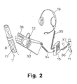
- FIG. 2 shows that such a normal actuation unit 15 can be arranged on a belt of an operator 30, spatially separated from the device 8.
- the device 8 has a handle 17 which can be grasped or encompassed by one hand of the operator 30 and that, according to preferred teaching, an intercom device 19 is provided here.
- the normal actuation unit 15 on the belt of the operator 30 also serves as a local control center including the intercom device 19.
- a relief device 21 for the supply line 7 and, in this respect, is also preferred at a point on the supply line 7 remote from the device 8, namely at a point close to the connection of the supply line 7 to the supply means source 3
- a shut-off device 22 for the supply line 7 are provided.
- the relief device 21 has a relief cross section which is approximately the same as the flow cross section the supply line 7 coincides, so that a very quick, effective relief can take place backwards.
- the supply line 7 may have a diameter of 42 mm, that is to say a flow cross section of approximately 1,330 mm 2.
- the relief device 21 would then also have this cross section. In the case of a supply line with a length of 400 m, the relief takes a few seconds, probably significantly less than 5 seconds be that no further supply means flows from the supply source 3.
- the actuation sensor 12 here specifically an indicator element of the actuation sensor 12
- the indicator element of the actuation sensor 12 is integrated in a protective glove 32 for the hand of the operator 30.
- an air coil 33 serves as an indicator element of the actuation sensor 12, which is integrated here in the grip surface of the protective glove 32.
- the air coil 33 is connected via a connecting cable 34 to central electronics or control electronics, for which more will be explained later.
- Plug or button contacts for connecting the connecting cable 34 are indicated in the wrist area of the protective glove 32.
- the air coil 33 is distributed over the gripping surface of the protective glove 32 and into the index finger and the thumb. It applies that it is particularly expedient if the indicator element is arranged in the gripping surface of the protective glove 32 at a largely motion-free location, in particular between the thumb and index finger.
- the indicator element does not necessarily have to be the in Fig. 2 have specifically shown large-scale expansion.
- a further safety effect is achieved, namely that reaching around the device 8 with the bare hand does not influence the actuation sensor 12, so an operator 30 is forced to wear the protective glove 32 at work.
- a film forming the influencing element can itself be wound or glued around a nozzle, a nozzle holder or the supply line 7.
- the influencing element can, for example, be integrated, in particular vulcanized, into a rubber hose which is attached to the device 8 at the appropriate point. In any case, it is particularly advisable to integrate the influencing element into the handle 17, preferably of course into the handle surface of the handle 17.
- the electronic proximity switch provided according to the invention which can preferably be operated in a contactless manner, can be operated as an actuation sensor by inductive, capacitive, optical, thermal or similar influencing by the operator.
- inductive proximity switch various further embodiments are to be explained, which are not shown in the figures.
- the actuation sensor it may be advisable to design the actuation sensor as a capacitive proximity sensor.
- the operator's hand could then, for example, influence the response capacity of the capacitive proximity sensor.
- the actuation sensor is designed as a magnetoelastic sensor.
- the magneto-elastic effect of such a sensor could be used when gripping a handle and the associated change in the mechanical load on an operator's work glove.
- a piezoelectric sensor could also be provided. Mechanical work would then be converted into electrical voltage.
- the actuation sensor could also be designed as a strain gauge sensor, in particular with at least one semiconductor strain gauge. Strain gauge sensors of this type can be used inexpensively and expediently, in particular with modern semiconductor technology.
- the actuation sensor is designed as a sound sensor, preferably as a structure-borne sound sensor, in particular as a structure-borne sound sensor.
- a structure-borne sound sensor is provided in a particularly preferred manner. Often this will be a microphone specially designed for structure-borne noise and structure-borne noise measurement.
- the supply means emerging from the device in particular a blasting agent of a blasting system conveyed by air, generates high-frequency vibrations in the device, in particular in the nozzle body of the blasting device.
- a structure-borne sound microphone is now in an operator's work glove integrated and connected to the control device, this structure-borne noise microphone registers the structure-borne noise in the nozzle body only when the work glove fits tightly around the handle of the nozzle body. This technique avoids the need to prepare the device in any way.
- the control device has at least one frequency filter assigned to the sound sensor.
- a frequency filter in the control device can e.g. B. as low-pass, high-pass or bandpass. It is also possible to connect several frequency filters in parallel in order to selectively determine different frequencies that usually occur when the device is in operation. Certain frequency ranges can also be filtered out with such frequency filters (target sound).
- the control device has a bridging switch and that when the device to be handled by the operator is started up, the actuation sensor can be bridged until the corresponding target sound occurs.
- the bypass switch in the control device is opened automatically as soon as a actuation sensor has emitted a desired signal which indicates the influence by the operator and the function of the device.
- the actuation sensor can be assigned a delay circuit if this appears expedient from the application. It is also not apparent in the figures that the actuation sensor, as already mentioned, can be designed as a proximity switch which can be influenced only by a special influencing element, in particular a foil, preferably made of aluminum, copper, a soft magnetic material with high initial permeability such as mumetal, or the like .
- a special influencing element in particular a foil, preferably made of aluminum, copper, a soft magnetic material with high initial permeability such as mumetal, or the like .
- Mum metal, or materials with a high initial permeability as are known, for example, for use in magnetic shielding, are particularly suitable here, since the actuation sensor cannot be influenced by metals such as steel, aluminum, zinc, copper or the like. Accidental influences can be prevented here safely.
- control electronics associated with the indicator element of the actuation sensor 12 can be integrated in the normal actuation unit 15 in the embodiment shown there. 2 also shows that the intercom device 19 is connected to the normal operating unit 15 via a cable 35.
- the connection of the control device 10 to the device 8 or the operator 30 via a cable 11 requires special attention.
- the cable 11 can be made in two parts, the power supply to the operator 30 taking place via one partial cable and the signal transmission taking place via the other partial cable.
- one-piece cables 11 can of course also be used.
- a particular problem is the protection of the cable 11 against damage.
- 2 in conjunction with FIG. 1 shows a particularly preferred exemplary embodiment in that a respiratory air line 36 is laid from supply source 3 or a pressure generator to operator 30 and cable 11 for connecting control device 10 is laid with the device 8 inside the breathing air line 36.
- This integration of cable 11 and breathing air line 36 for an otherwise necessary protective ventilation of the operator 30 ensures a particularly protected routing of the cable 11 to the operator 30.
- the cable 11 can of course also be used in other existing lines. for example, into the supply line 7, but expediently be integrated into an auxiliary air line that sometimes runs parallel to the supply line 7. What is explained below for integration into the breathing air line 36 also applies analogously to the integration into other lines.
- the breathing air line 36 should of course each have a cable connection 37 or a cable entry near the control device 10 and near the device 8.
- a cable connection 37 can be designed as a plug connection in various conceivable ways. Designed as a cable entry or cable entry, a real connection device is not necessary. In contrast, it is then necessary to seal the cable 11 that is introduced or carried out. For the rest, reference can be made to the state of the art for the construction of such connections or entries.
- Fig. 1 shows in this respect a special design as here the breathing air line 36 or any other line consists of individual line pieces 39 that can be coupled via connecting pieces 38 and the connecting pieces 38 simultaneously the pneumatic connection of the line pieces 39 and the electrical connection of individual cable pieces of the cable 11 serve. 4 shows this schematically for two line pieces 39.
- shut-off devices are in the state of the ball valve valves, slide or the like ..
- a relief device 21 for the supply line 7 and a shut-off device 22 The exemplary embodiments shown here require that the supply line 7 at least in the area of Relief device 21 and / or the shut-off device 22 can be squeezed together. This applies on the one hand to the supply line 7 itself, and on the other hand to a relief connection 50 guided through the relief device 21.
- the relief device 21 and / or the shut-off device 22 have one or each movable squeezing element 51 for squeezing the corresponding supply line 7 together or the relief connector 50.
- the pinch element 51 can be moved by a pneumatic or hydraulic drive, in particular a bellows cylinder 52.
- the initially preferred exemplary embodiment shown in FIG. 3 has supply line 7 and relief connector 50 running next to one another, running parallel to one another.
- a squeeze element 51 is arranged between the supply line 7 and the relief port 50.
- the actuator is therefore double-acting.
- a spring 55 designed as a helical compression spring is provided, which normally combines the bellows cylinder 52 tries to press and moves the squeeze element 51 in the construction shown here in the direction of the relief state. Only when the bellows cylinder 52 is pressurized is the supply line 7 opened and the relief port 50 closed, does the control pressure drop, then the spring 55 presses the bellows cylinder 52 upward in FIG. 3 and thus squeezes the supply line 7 together.
- FIG. 1 shows in the previously explained context that the control pressure line 54 for the relief device 21 and the shut-off device 22 can be easily connected to a common compressed air generator to which, for example, the compressed air line 1 assigned to the supply medium source 3 is also connected.
- FIG. 3 also shows a control valve 56 on the control pressure line 54, which in the exemplary embodiment shown here can be designed as a simple 3/2 valve.
- the further exemplary embodiment of the teaching of the invention which has been explained in principle in FIGS. 4 and 5, also initially has a squeezing element 51 and a bellows cylinder 52 as a pneumatic drive.
- This exemplary embodiment explained with reference to FIG. 4 for the shut-off device 22 of the supply line 7, is distinguished by particular simplicity and excellent retrofittability on existing supply lines 7.
- the housing 53 is here box-shaped with side walls and end walls, the end walls at the upper edge each having approximately U-shaped recesses for receiving the supply line 7.
- the supply line 7 can be inserted into these recesses 57 from above. As shown in FIG.
- the housing 53 is then closed by an insertable cover 58, which is prevented from being lifted upwards from the housing 53 by inwardly bent retaining flanges on the housing 53 in the inserted position.
- a corresponding squeeze element 59 is on the inside of the cover 58 to the squeeze element 51 on the bellows cylinder 52, which is designed here as a squeeze bar arranged transversely to the supply line 7 orderly. If compressed air is supplied to the bellows cylinder 52 via the control pressure line 54, which is also present here, when the supply line 7 is inserted, the bellows cylinder expands, raises the squeeze element 51 upwards and thus squeezes the supply line 7 between the squeeze elements 51 and 59.
- a pressure relief line 60 for the bellows cylinder 52 is also shown.
- a control valve not shown here, for example a 4/2 control valve, can be connected to the lines 54, 60.
- FIG. 5 now shows in an easily understandable representation the interaction of a relief device 21 and a shut-off device 22, both constructed according to the system of FIG.
- the two bellows cylinders 52 which also form the drive for the squeezing elements 51 in the exemplary embodiment shown here, are connected via a control valve 56, which is designed here as a 5/2-way valve, to a control pressure line (not shown) and to one another, so that in a first / 0 signal always one of the two bellows cylinders 52 extended and the other of the two bellows cylinders 52 is contracted.
- the left half of FIG. 5 shows the normal operating state with the supply line 7 open and the relief connector 50 squeezed together, the direction of flow being shown at the bottom left in FIG. 5.
- the relief position is then shown in the right half of FIG. 5 with the supply line 7 squeezed together and the relief port 50 open, the flow directions again at the bottom right.
- This technology is particularly useful and can be easily retrofitted to an existing system.
- the design of the drives as bellows cylinders 52 is robust and largely maintenance-free, especially since the bellows cylinders 52 in the present exemplary embodiment are also protected against damage by the housing 53. Pneumatic control from the compressed air source via the control pressure line is typical of the system and therefore particularly useful.
Landscapes
- Engineering & Computer Science (AREA)
- Mechanical Engineering (AREA)
- General Engineering & Computer Science (AREA)
- Fluid-Pressure Circuits (AREA)
- Gloves (AREA)
- Auxiliary Devices For Machine Tools (AREA)
Priority Applications (1)
| Application Number | Priority Date | Filing Date | Title |
|---|---|---|---|
| AT87116884T ATE63625T1 (de) | 1986-11-20 | 1987-11-16 | Sicherheitseinrichtung. |
Applications Claiming Priority (4)
| Application Number | Priority Date | Filing Date | Title |
|---|---|---|---|
| DE3639628 | 1986-11-20 | ||
| DE3639628 | 1986-11-20 | ||
| DE3643060 | 1986-12-17 | ||
| DE19863643060 DE3643060A1 (de) | 1986-04-22 | 1986-12-17 | Sicherheitseinrichtung |
Related Child Applications (1)
| Application Number | Title | Priority Date | Filing Date |
|---|---|---|---|
| EP88113579.2 Division-Into | 1987-11-16 |
Publications (3)
| Publication Number | Publication Date |
|---|---|
| EP0268244A2 true EP0268244A2 (fr) | 1988-05-25 |
| EP0268244A3 EP0268244A3 (en) | 1988-11-30 |
| EP0268244B1 EP0268244B1 (fr) | 1991-05-15 |
Family
ID=25849560
Family Applications (2)
| Application Number | Title | Priority Date | Filing Date |
|---|---|---|---|
| EP19870116884 Expired - Lifetime EP0268244B1 (fr) | 1986-11-20 | 1987-11-16 | Dispositif de sécurité |
| EP19880113579 Expired - Lifetime EP0299541B1 (fr) | 1986-11-20 | 1987-11-16 | Dispositif de sécurité pour un dispositif manipulé par un opérateur |
Family Applications After (1)
| Application Number | Title | Priority Date | Filing Date |
|---|---|---|---|
| EP19880113579 Expired - Lifetime EP0299541B1 (fr) | 1986-11-20 | 1987-11-16 | Dispositif de sécurité pour un dispositif manipulé par un opérateur |
Country Status (4)
| Country | Link |
|---|---|
| US (2) | US4814632A (fr) |
| EP (2) | EP0268244B1 (fr) |
| DE (2) | DE3769984D1 (fr) |
| ES (2) | ES2022270B3 (fr) |
Cited By (8)
| Publication number | Priority date | Publication date | Assignee | Title |
|---|---|---|---|---|
| WO1991013286A1 (fr) * | 1990-02-28 | 1991-09-05 | Cabot Safety Corporation | Systeme de detection pour equipement de securite |
| EP0362937A3 (fr) * | 1988-10-04 | 1992-03-11 | Giorgio Grasselli | Système de sécurité pour appareillage actionné par moteur |
| FR2673265A1 (fr) * | 1991-02-21 | 1992-08-28 | Townsend Engineering Co | Moyen de securite pour machines a moteur, en particulier pour machines a depouiller la viande. |
| DE19941767A1 (de) * | 1999-09-02 | 2001-05-03 | Schoebel Industriereinigung Gm | Vorrichtung zur Personenüberwachung |
| US7757982B2 (en) | 2006-09-28 | 2010-07-20 | Fellowes, Inc. | Shredder with intelligent activation switch |
| US9573135B2 (en) | 2005-07-11 | 2017-02-21 | Fellowes, Inc. | Shredder with thickness detector |
| US9669410B2 (en) | 2007-08-02 | 2017-06-06 | ACCO Brands Corporation | Shredding machine |
| US9724704B2 (en) | 2007-10-04 | 2017-08-08 | Fellowes Inc. | Shredder thickness with anti-jitter feature |
Families Citing this family (42)
| Publication number | Priority date | Publication date | Assignee | Title |
|---|---|---|---|---|
| DE3912287A1 (de) * | 1989-04-14 | 1990-10-18 | Diehl Gmbh & Co | Ladeschuetzenausruestung |
| US5201684A (en) * | 1989-10-10 | 1993-04-13 | Townsend Engineering Company | Safety means for powered machinery |
| US5025175A (en) * | 1989-10-10 | 1991-06-18 | Townsend Engineering Company | Safety means for powered machinery |
| JPH05502130A (ja) * | 1989-11-22 | 1993-04-15 | ラッセル、デヴィッド、シー | コンピューター制御システム |
| US5285530A (en) * | 1993-02-03 | 1994-02-15 | Nardone Jr Robert J | Ear muff device |
| US5963151A (en) * | 1993-10-14 | 1999-10-05 | Hubbard; Rayford C. | Bus stop call system |
| US5588593A (en) * | 1995-06-05 | 1996-12-31 | C.H. Heist Corp | Safety apparatus for high pressure liquid jet system |
| US5666010A (en) * | 1995-08-30 | 1997-09-09 | Stratiotis; Gus | Safety system for machine tools |
| AT408325B (de) * | 1998-03-13 | 2001-10-25 | Keba Gmbh & Co | Sicherheitsschalteinrichtung für ein handbediengerät zur steuerung von maschinen |
| FR2779669B1 (fr) * | 1998-06-16 | 2000-08-04 | Electronique Angelidis Et Sarr | Dispositif de securite pour la conduite d'une machine-outil |
| CZ20004731A3 (cs) * | 1998-06-16 | 2001-08-15 | Intelligent Safety Development | Individuální ochranné zařízení proti mechanickým, elektrickým nebo tepelným rizikům |
| US6211672B1 (en) * | 1998-12-21 | 2001-04-03 | Triple Tech, Llc | Human appendage mounted metal detector |
| WO2001035791A2 (fr) * | 1999-11-15 | 2001-05-25 | Michael Hermann | Ceinture de securite |
| AU6700601A (en) * | 2000-06-19 | 2002-01-02 | Hygrama Ag | Intrinsically safe microprocessor controlled pressure regulator |
| US6501281B1 (en) | 2000-07-19 | 2002-12-31 | Delta Systems, Inc. | Capacitive, operator-sensing circuit for disabling engine of mobile power equipment |
| US7145477B1 (en) * | 2001-09-19 | 2006-12-05 | Mcbain Theodore | Anti-terrorist aircraft pilot sensor system and method |
| US6948398B2 (en) * | 2002-07-22 | 2005-09-27 | Deere & Company | Joystick with enabling sensors |
| US6938795B2 (en) | 2003-11-26 | 2005-09-06 | Nordson Corporation | Hand-held fluid dispenser system and method of operating hand-held fluid dispenser systems |
| US7034552B2 (en) * | 2004-02-17 | 2006-04-25 | Markus Kirchner | Operator sensing circuit for disabling motor of power equipment |
| US7236849B2 (en) * | 2004-02-23 | 2007-06-26 | Walsh Matthew J | Safety system for power equipment |
| US7661614B2 (en) * | 2004-09-10 | 2010-02-16 | Fellowes Inc. | Shredder throat safety system |
| US7631822B2 (en) | 2004-09-10 | 2009-12-15 | Fellowes Inc. | Shredder with thickness detector |
| US8870106B2 (en) | 2004-09-10 | 2014-10-28 | Fellowes, Inc. | Shredder with thickness detector |
| USD611089S1 (en) | 2006-07-25 | 2010-03-02 | Fellowes, Inc. | Top surface of a shredder |
| US8201761B2 (en) | 2009-01-05 | 2012-06-19 | Fellowes, Inc. | Thickness sensor based motor controller |
| US8430347B2 (en) * | 2009-01-05 | 2013-04-30 | Fellowes, Inc. | Thickness adjusted motor controller |
| US9058707B2 (en) * | 2009-02-17 | 2015-06-16 | Ronald C. Benson | System and method for managing and maintaining abrasive blasting machines |
| US8091809B2 (en) * | 2009-03-24 | 2012-01-10 | Fellowes, Inc. | Shredder with jam proof system |
| US8205815B2 (en) * | 2009-05-15 | 2012-06-26 | Fellowes, Inc. | Paper alignment sensor arrangement |
| US8678305B2 (en) * | 2009-06-18 | 2014-03-25 | Fellowes, Inc. | Restrictive throat mechanism for paper shredders |
| US8550387B2 (en) * | 2009-06-18 | 2013-10-08 | Tai Hoon K. Matlin | Restrictive throat mechanism for paper shredders |
| US8382019B2 (en) | 2010-05-03 | 2013-02-26 | Fellowes, Inc. | In-rush current jam proof sensor control |
| US8511593B2 (en) | 2010-05-28 | 2013-08-20 | Fellowes, Inc. | Differential jam proof sensor for a shredder |
| US9044760B2 (en) | 2010-12-17 | 2015-06-02 | Jeff Buchanan | Wearable safety device for cutting machine |
| FR2984294A1 (fr) * | 2011-12-19 | 2013-06-21 | Haulotte Group | Dispositif de protection d'un utilisateur d'une nacelle elevatrice et nacelle elevatrice comprenant un tel dispositif |
| US8936042B2 (en) * | 2012-09-24 | 2015-01-20 | Graco Minnesota Inc | Dual control dead man system |
| DE102013102334A1 (de) * | 2013-03-08 | 2014-09-11 | Renfert Gmbh | Abrasivstrahlvorrichtung |
| AT519719B1 (de) * | 2017-02-27 | 2019-01-15 | Bft Gmbh | Dosiereinrichtung für Abrasivmittel in Wasserstrahl-Schneidanlagen |
| US10034501B2 (en) | 2017-05-19 | 2018-07-31 | Jesse Jensen | Wearable metal detection system |
| US20210187773A1 (en) * | 2018-05-31 | 2021-06-24 | Hollymatic Corporation | Method and system to control, automate, monitor, and shut down a deli slicer |
| EP4282546B1 (fr) * | 2022-05-24 | 2025-03-05 | Andreas Stihl AG & Co. KG | Appareil de nettoyage haute pression |
| US12592349B1 (en) | 2023-08-11 | 2026-03-31 | George E. Lyras | Protective safety glove |
Family Cites Families (28)
| Publication number | Priority date | Publication date | Assignee | Title |
|---|---|---|---|---|
| GB700751A (en) * | 1950-06-30 | 1953-12-09 | Dunlop Rubber Co | Automatic means for rendering a machine inoperative |
| US3034263A (en) * | 1959-08-07 | 1962-05-15 | Ruric N Mcdaniel | Sand blasting apparatus |
| US3370233A (en) * | 1964-06-04 | 1968-02-20 | Triplett Electrical Instr Co | Test apparatus for determining beta and leakage current of an in-circuit or out-of-circuit transistor |
| FR1564099A (fr) * | 1968-03-13 | 1969-04-18 | ||
| US3784842A (en) * | 1972-02-03 | 1974-01-08 | F Kremer | Body current activated circuit breaker |
| SU644489A1 (ru) * | 1975-05-04 | 1979-01-30 | Куйбышевский Филиал Всесоюзного Института По Проектированию Организации Энергетического Строительства "Оргэнергострой" | Электрододержатель |
| CH584981A5 (en) * | 1975-05-23 | 1977-02-15 | Baumgartner M Ag | Proximity switch with two capacitative sensor plates - is activated by imbalance in outputs of two HF oscillators coupled to comparator |
| FR2341806A1 (fr) * | 1976-02-20 | 1977-09-16 | Irrifrance | Vanne motorisee par un verin hydraulique a soufflet |
| SU710548A1 (ru) * | 1977-08-17 | 1980-01-25 | Куйбышевский Филиал Всесоюзного Института По Проектированию Организации Энергетического Строительства | Защитна рукавица дл электросварщика |
| US4195722A (en) * | 1978-04-19 | 1980-04-01 | Outboard Marine Corporation | Circuit for a power operated machine |
| US4321841A (en) * | 1980-04-10 | 1982-03-30 | Steelcase Inc. | Press safety device |
| DE3025895A1 (de) * | 1980-07-09 | 1982-02-18 | Sata-Farbspritztechnik GmbH, 7140 Ludwigsburg | Luftstrahlgeraet |
| DE8024045U1 (de) * | 1980-09-09 | 1981-02-12 | Fertl, Klaus, 8860 Noerdlingen | Anordnung zum Unterbrechen des Strömungsflusses in Schläuchen |
| US4479571A (en) * | 1981-11-23 | 1984-10-30 | Eliot Sigdon A | Protective glove system |
| US4586387A (en) * | 1982-06-16 | 1986-05-06 | The Commonwealth Of Australia | Flight test aid |
| FR2540148B1 (fr) * | 1983-02-02 | 1986-03-21 | Seb Sa | Dispositif electronique de securite pour fer a repasser electrique |
| JPS6081306A (ja) * | 1983-10-07 | 1985-05-09 | 日本碍子株式会社 | 作業用ヘルメツト |
| US4649374A (en) * | 1984-01-06 | 1987-03-10 | Spectrascan, Inc. | Electrostatic system monitor and method therefor |
| US4686352B1 (en) * | 1984-04-27 | 1993-12-14 | Sunbeam Corporation | Electronic pressing iron |
| US4621300A (en) * | 1984-07-05 | 1986-11-04 | Summerer Ray E | Safety monitoring system for punch press operators |
| US4635516A (en) * | 1984-09-17 | 1987-01-13 | Giancarlo Giannini | Tone generating glove and associated switches |
| DE8526106U1 (de) * | 1985-09-12 | 1986-04-17 | Sapi Drucklufttechnik GmbH, 8860 Nördlingen | Pneumatische Schnellabschaltung mit Sicherheitsschließung |
| US4673798A (en) * | 1986-04-02 | 1987-06-16 | John Zink Company | Dual temperature electric curling iron having a safety shut-off circuit |
| DE8611018U1 (de) * | 1986-04-22 | 1987-08-20 | Ernst Peiniger GmbH Unternehmen für Bautenschutz, 45145 Essen | Sicherheitseinrichtung |
| DE8613771U1 (de) * | 1986-05-21 | 1987-08-06 | Ernst Peiniger GmbH Unternehmen für Bautenschutz, 45145 Essen | Sicherheitseinrichtung |
| DE8631049U1 (de) * | 1986-11-20 | 1987-08-13 | Ernst Peiniger GmbH Unternehmen für Bautenschutz, 4300 Essen | Sicherheitseinrichtung |
| DE8633717U1 (de) * | 1986-12-17 | 1987-08-06 | Ernst Peiniger GmbH Unternehmen für Bautenschutz, 4300 Essen | Sicherheitseinrichtung |
| DE8707316U1 (de) * | 1987-05-21 | 1987-10-15 | Wiegand, Hubert, Dipl.-Ing., 4790 Paderborn | Strahlschlauch mit Metallgewebeummantelung und Handschuh mit Metallgewebeinnenfläche |
-
1987
- 1987-11-16 EP EP19870116884 patent/EP0268244B1/fr not_active Expired - Lifetime
- 1987-11-16 EP EP19880113579 patent/EP0299541B1/fr not_active Expired - Lifetime
- 1987-11-16 ES ES87116884T patent/ES2022270B3/es not_active Expired - Lifetime
- 1987-11-16 ES ES88113579T patent/ES2022557B3/es not_active Expired - Lifetime
- 1987-11-16 DE DE8888113579T patent/DE3769984D1/de not_active Expired - Fee Related
- 1987-11-16 DE DE8787116884T patent/DE3770123D1/de not_active Expired - Fee Related
- 1987-11-20 US US07/123,424 patent/US4814632A/en not_active Expired - Fee Related
-
1988
- 1988-11-02 US US07/266,483 patent/US4914721A/en not_active Expired - Fee Related
Cited By (10)
| Publication number | Priority date | Publication date | Assignee | Title |
|---|---|---|---|---|
| EP0362937A3 (fr) * | 1988-10-04 | 1992-03-11 | Giorgio Grasselli | Système de sécurité pour appareillage actionné par moteur |
| WO1991013286A1 (fr) * | 1990-02-28 | 1991-09-05 | Cabot Safety Corporation | Systeme de detection pour equipement de securite |
| FR2673265A1 (fr) * | 1991-02-21 | 1992-08-28 | Townsend Engineering Co | Moyen de securite pour machines a moteur, en particulier pour machines a depouiller la viande. |
| NL9100650A (nl) * | 1991-02-21 | 1992-09-16 | Townsend Engineering Co | Veiligheidsinrichting voor electrisch aangedreven machines. |
| DE19941767A1 (de) * | 1999-09-02 | 2001-05-03 | Schoebel Industriereinigung Gm | Vorrichtung zur Personenüberwachung |
| US9573135B2 (en) | 2005-07-11 | 2017-02-21 | Fellowes, Inc. | Shredder with thickness detector |
| US7757982B2 (en) | 2006-09-28 | 2010-07-20 | Fellowes, Inc. | Shredder with intelligent activation switch |
| US9669410B2 (en) | 2007-08-02 | 2017-06-06 | ACCO Brands Corporation | Shredding machine |
| US10576476B2 (en) | 2007-08-02 | 2020-03-03 | ACCO Brands Corporation | Shredding machine |
| US9724704B2 (en) | 2007-10-04 | 2017-08-08 | Fellowes Inc. | Shredder thickness with anti-jitter feature |
Also Published As
| Publication number | Publication date |
|---|---|
| DE3769984D1 (de) | 1991-06-13 |
| US4914721A (en) | 1990-04-03 |
| EP0268244A3 (en) | 1988-11-30 |
| ES2022270B3 (es) | 1991-12-01 |
| EP0268244B1 (fr) | 1991-05-15 |
| US4814632A (en) | 1989-03-21 |
| EP0299541A3 (en) | 1989-04-05 |
| DE3770123D1 (de) | 1991-06-20 |
| EP0299541A2 (fr) | 1989-01-18 |
| EP0299541B1 (fr) | 1991-05-08 |
| ES2022557B3 (es) | 1991-12-01 |
Similar Documents
| Publication | Publication Date | Title |
|---|---|---|
| EP0268244A2 (fr) | Dispositif de sécurité | |
| DE3643060C2 (fr) | ||
| DE102011119784A1 (de) | Fluidbetätigte Greifvorrichtung mit Sicherheitseinrichtung | |
| DE10009167B4 (de) | Luftspareinrichtung für eine Saugvorrichtung | |
| DE202015009641U1 (de) | An eine Energiequelle angeschlossenes Arbeitsgerät | |
| EP1387971B1 (fr) | Vanne a tiroir | |
| DE3108884C2 (de) | Vorrichtung zur Beeinflussung des Knickwinkels eines Gelenkfahrzeuges | |
| DE2831647C2 (de) | Kupplung zum Anschließen von Versorgungsgasleitungen an metallurgischen Gefäßen | |
| EP0156939A1 (fr) | Outil dirigé par pression | |
| DE202016003670U1 (de) | Anbindungsplatte und Pneumatikzylinder mit integrierter Anbindungsplatte | |
| EP1134180A2 (fr) | Chariot élévateur à fourches avec un boulon d' attelage | |
| DE8633717U1 (de) | Sicherheitseinrichtung | |
| DE19503413C2 (de) | Vorrichtung zum Einbringen von Schüttgut in eine Förderleitung | |
| DE8631049U1 (de) | Sicherheitseinrichtung | |
| DE19819270B4 (de) | Seitenstapler | |
| DE3300034C2 (de) | Schalt- und Steuereinrichtung für durch ein Arbeitsfluid antreibbare Arbeitsgeräte | |
| EP2637853A1 (fr) | Presse | |
| DE2947842C2 (de) | Hydraulische Sicherheitssteuerung mit Druckstufenregelventil | |
| DE1955811C3 (de) | Pneumatisch wirkende Einrichtung zur Begrenzung des Vorschubweges der Trennschleifscheibe in Trennschleifmaschinen | |
| DE10052258C1 (de) | Verfahren zum Bremsen eines hängend verfahrbaren Transportverbandes und Anordnung zur Durchführung des Verfahrens | |
| EP3033555B1 (fr) | Ensemble de vanne pour une i.s. machine | |
| CH593860A5 (en) | Load holder for heavy lifting tackle - has locking pin advanced by contact plate across load lifting bracket | |
| DE29605704U1 (de) | Schnellabschaltvorrichtung für ein Sandstrahlgerät | |
| DE3203432C2 (de) | Handbedienbares, wegeabhängig arbeitendes Vorschaltsteuergerät auf dem Führerstand einer Baumaschine | |
| DE2524780C3 (de) | Überwachungs- und Sicherheitseinrichtung für eine zweihandbetätigte Steuereinrichtung |
Legal Events
| Date | Code | Title | Description |
|---|---|---|---|
| PUAI | Public reference made under article 153(3) epc to a published international application that has entered the european phase |
Free format text: ORIGINAL CODE: 0009012 |
|
| AK | Designated contracting states |
Kind code of ref document: A2 Designated state(s): AT BE CH DE ES FR GB GR IT LI LU NL SE |
|
| PUAL | Search report despatched |
Free format text: ORIGINAL CODE: 0009013 |
|
| 17P | Request for examination filed |
Effective date: 19880820 |
|
| AK | Designated contracting states |
Kind code of ref document: A3 Designated state(s): AT BE CH DE ES FR GB GR IT LI LU NL SE |
|
| 17Q | First examination report despatched |
Effective date: 19890908 |
|
| GRAA | (expected) grant |
Free format text: ORIGINAL CODE: 0009210 |
|
| AK | Designated contracting states |
Kind code of ref document: B1 Designated state(s): AT BE CH DE ES FR GB GR IT LI LU NL SE |
|
| PG25 | Lapsed in a contracting state [announced via postgrant information from national office to epo] |
Ref country code: SE Effective date: 19910515 Ref country code: GR Free format text: LAPSE BECAUSE OF FAILURE TO SUBMIT A TRANSLATION OF THE DESCRIPTION OR TO PAY THE FEE WITHIN THE PRESCRIBED TIME-LIMIT Effective date: 19910515 Ref country code: GB Effective date: 19910515 |
|
| REF | Corresponds to: |
Ref document number: 63625 Country of ref document: AT Date of ref document: 19910615 Kind code of ref document: T |
|
| ITF | It: translation for a ep patent filed | ||
| REF | Corresponds to: |
Ref document number: 3770123 Country of ref document: DE Date of ref document: 19910620 |
|
| ET | Fr: translation filed | ||
| GBV | Gb: ep patent (uk) treated as always having been void in accordance with gb section 77(7)/1977 [no translation filed] | ||
| PG25 | Lapsed in a contracting state [announced via postgrant information from national office to epo] |
Ref country code: LU Free format text: LAPSE BECAUSE OF NON-PAYMENT OF DUE FEES Effective date: 19911130 |
|
| PLBE | No opposition filed within time limit |
Free format text: ORIGINAL CODE: 0009261 |
|
| STAA | Information on the status of an ep patent application or granted ep patent |
Free format text: STATUS: NO OPPOSITION FILED WITHIN TIME LIMIT |
|
| 26N | No opposition filed | ||
| PGFP | Annual fee paid to national office [announced via postgrant information from national office to epo] |
Ref country code: FR Payment date: 19921027 Year of fee payment: 6 |
|
| PGFP | Annual fee paid to national office [announced via postgrant information from national office to epo] |
Ref country code: ES Payment date: 19921104 Year of fee payment: 6 |
|
| PGFP | Annual fee paid to national office [announced via postgrant information from national office to epo] |
Ref country code: BE Payment date: 19931109 Year of fee payment: 7 |
|
| PGFP | Annual fee paid to national office [announced via postgrant information from national office to epo] |
Ref country code: AT Payment date: 19931110 Year of fee payment: 7 |
|
| PG25 | Lapsed in a contracting state [announced via postgrant information from national office to epo] |
Ref country code: ES Free format text: LAPSE BECAUSE OF NON-PAYMENT OF DUE FEES Effective date: 19931117 |
|
| PGFP | Annual fee paid to national office [announced via postgrant information from national office to epo] |
Ref country code: CH Payment date: 19931123 Year of fee payment: 7 |
|
| PGFP | Annual fee paid to national office [announced via postgrant information from national office to epo] |
Ref country code: NL Payment date: 19931130 Year of fee payment: 7 |
|
| PGFP | Annual fee paid to national office [announced via postgrant information from national office to epo] |
Ref country code: DE Payment date: 19931230 Year of fee payment: 7 |
|
| PG25 | Lapsed in a contracting state [announced via postgrant information from national office to epo] |
Ref country code: FR Effective date: 19940729 |
|
| REG | Reference to a national code |
Ref country code: FR Ref legal event code: ST |
|
| PG25 | Lapsed in a contracting state [announced via postgrant information from national office to epo] |
Ref country code: AT Effective date: 19941116 |
|
| PG25 | Lapsed in a contracting state [announced via postgrant information from national office to epo] |
Ref country code: LI Effective date: 19941130 Ref country code: CH Effective date: 19941130 Ref country code: BE Effective date: 19941130 |
|
| BERE | Be: lapsed |
Owner name: ERNST PEINIGER G.M.B.H. UNTERNEHMEN FUR BAUTENSCH Effective date: 19941130 |
|
| PG25 | Lapsed in a contracting state [announced via postgrant information from national office to epo] |
Ref country code: NL Effective date: 19950601 |
|
| NLV4 | Nl: lapsed or anulled due to non-payment of the annual fee | ||
| REG | Reference to a national code |
Ref country code: CH Ref legal event code: PL |
|
| PG25 | Lapsed in a contracting state [announced via postgrant information from national office to epo] |
Ref country code: DE Effective date: 19950801 |
|
| REG | Reference to a national code |
Ref country code: ES Ref legal event code: FD2A Effective date: 19941214 |
|
| PG25 | Lapsed in a contracting state [announced via postgrant information from national office to epo] |
Ref country code: IT Free format text: LAPSE BECAUSE OF NON-PAYMENT OF DUE FEES;WARNING: LAPSES OF ITALIAN PATENTS WITH EFFECTIVE DATE BEFORE 2007 MAY HAVE OCCURRED AT ANY TIME BEFORE 2007. THE CORRECT EFFECTIVE DATE MAY BE DIFFERENT FROM THE ONE RECORDED. Effective date: 20051116 |