EP0268337A1 - Dispositif pour commander l'alimentation de puissance d'une charge inductrice - Google Patents
Dispositif pour commander l'alimentation de puissance d'une charge inductrice Download PDFInfo
- Publication number
- EP0268337A1 EP0268337A1 EP87202209A EP87202209A EP0268337A1 EP 0268337 A1 EP0268337 A1 EP 0268337A1 EP 87202209 A EP87202209 A EP 87202209A EP 87202209 A EP87202209 A EP 87202209A EP 0268337 A1 EP0268337 A1 EP 0268337A1
- Authority
- EP
- European Patent Office
- Prior art keywords
- input
- signal
- phase
- current detector
- zero crossing
- Prior art date
- Legal status (The legal status is an assumption and is not a legal conclusion. Google has not performed a legal analysis and makes no representation as to the accuracy of the status listed.)
- Withdrawn
Links
- 230000001939 inductive effect Effects 0.000 title claims abstract description 10
- 230000000977 initiatory effect Effects 0.000 claims abstract description 3
- 239000004065 semiconductor Substances 0.000 claims description 2
- 239000004020 conductor Substances 0.000 description 17
- 238000009413 insulation Methods 0.000 description 3
- 230000006698 induction Effects 0.000 description 2
- 230000007935 neutral effect Effects 0.000 description 2
- 238000004804 winding Methods 0.000 description 2
- 230000004913 activation Effects 0.000 description 1
- 238000010276 construction Methods 0.000 description 1
- 230000008878 coupling Effects 0.000 description 1
- 238000010168 coupling process Methods 0.000 description 1
- 238000005859 coupling reaction Methods 0.000 description 1
- 230000001419 dependent effect Effects 0.000 description 1
- 230000000694 effects Effects 0.000 description 1
- 230000006870 function Effects 0.000 description 1
- 230000017525 heat dissipation Effects 0.000 description 1
- 230000002452 interceptive effect Effects 0.000 description 1
- 230000005693 optoelectronics Effects 0.000 description 1
- 230000000630 rising effect Effects 0.000 description 1
Images
Classifications
-
- H—ELECTRICITY
- H02—GENERATION; CONVERSION OR DISTRIBUTION OF ELECTRIC POWER
- H02M—APPARATUS FOR CONVERSION BETWEEN AC AND AC, BETWEEN AC AND DC, OR BETWEEN DC AND DC, AND FOR USE WITH MAINS OR SIMILAR POWER SUPPLY SYSTEMS; CONVERSION OF DC OR AC INPUT POWER INTO SURGE OUTPUT POWER; CONTROL OR REGULATION THEREOF
- H02M1/00—Details of apparatus for conversion
- H02M1/08—Circuits specially adapted for the generation of control voltages for semiconductor devices incorporated in static converters
- H02M1/084—Circuits specially adapted for the generation of control voltages for semiconductor devices incorporated in static converters using a control circuit common to several phases of a multi-phase system
Definitions
- the invention relates to an apparatus for controlling the electric power supply from a three-phase mains into an inductive load, comprising a controllable electronic switch means, one for each of the three phases, having an input for the respective phase, an output to said inductive load and an input for a control signal, a direction-of-current detector for at least one of said phases and connected into a shunt across said electronic switch means, an electronic synchronization signal-generator having an input for the output signal of the direction-of-current detector, and a control signal generator having an input for the synchronization signal and an input for a set signal for controlling said electric switch means.
- Such an apparatus for controlling the number of revolutions of a three-phase electric motor of the induction type by means of a control signal.
- each of the three-phase parts of the motor is controlled by separate electronic switches in order to synchronously feed the rotary magnetic field of the induction motor.
- the motor runs silently and is free of vibrations, and heat dissipation remains limited.
- the electric current flows from a phase conductor of the mains through the respective electronic switch and a motor winding to the neutral conductor of the three-phase mains.
- This object is has appeared necessary that the electronic switches are actually received in the phase conductors and not between phase and zero conductors or between two phase conductors, respectively.
- any phase current flows through two or three electronic switches.
- the output signal of the direction-of-current detector is thus affected by a current or currents initiated in the other phase or phases, respectively. This explains why the application of a direction-of-current detector in addition to correct reference signals also yields erroneous reference signals, interfering with the generation of the synchronization signal and introducing errors in the energy supply to the load.
- the voltage across an electronic switch in a predetermined phase conductor of which the direction-of-current detector makes use is affected by switching actions of electronic switches in the other phase conductors.
- the effect of an electronic switch in one particular other phase conductor (phase R affected by phase T, phase S by phase R and phase T by phase S) and within a certain time interval can be so considerable that the direction-of-current detector emits erroneous current zero crossing signals.
- Said time interval is at about 33° after the rising voltage zero crossing of the phase in question with respect to the zero conductor. The duration of the interval corresponds to about 15° of a cycle.
- the apparatus of the type described in the introduction is characterized by a delay means having an input for a zero crossing signal from one phase of the mains voltage and initiating with said zero crossing signal a predetermined time period, and a logical gate means having an input for the output signal of the direction-of-current detector and an input for the output signal of said delay means, and an output to the input of said electronic synchronization signal-generator.
- the predetermined period is a function of the mains frequency; the time period also represents a certain phase-angle.
- the apparatus according to the invention is furthermore characterized in that said zero crossing signal is the voltage zero crossing signal that is derived from the output signal of a voltage polarity detector in a branch of a star connection between the inputs for the mains voltage of the respective electronic switches.
- the apparatus according to the invention is characterized in that the zero crossing signal is derived from the output signal of the direction-of-current detector.
- the electronic switches in the apparatus according to the invention are preferably implemented with a semi-conductor switch of the TRIAC type.
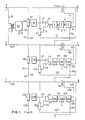
- Fig. 1 shows the preferred embodiment of the apparatus according to the invention.
- the three phases of the mains can be connected to terminals R, S and T, respectively.
- the connection of an inductive load takes place at the terminals U, V and W, respectively.
- the apparatus provides a similar construction for each of the Phases.
- the electronic circuits require a power supply that has no electrically conductive junctions with the phases. Therefore there is one single power supply provided for the three electronic circuits, deriving energy through a transformer 51 from a lead 50 connected between the phase terminals R and S.
- a voltage polarity detector 20, 120, 220 in each of the respective branches tracks the polarity of the voltage in the phase conductor and the output signal of the detector 20, 120, 220 is thus an indication of the zero crossing of the voltage in the phase conductor.
- a second zero crossing signal can be derived from a direction-of-current detector 3, 103, 203 that has been included parallel to the electronic switch 6, 7; 106, 107; 206, 207 in a shunt 10, 110, 210 of the pertaining phase conductor. Due to the inductive load across the terminals U, V and W the zero crossing signal that is derived from the phase voltage generally leads that of the phase current. The distance in time between the zero crossing signals is dependent on the cos phi of the load.
- the voltage zero crossing signal originating from the voltage polarity detector 20 is fed through the output 19 of the detector 20 to a monostable multivibrator 18 in which it starts an event determining a time period the end of which is passed on via an output 17 to an input of an AND gate 16.
- a second input 12 of the AND gate 16 receives the current zero crossing signal derived from the direction-of-current detector 3, so that at the input 11 of an electronic synchronization signal generator 4 a start signal appears the moment the event determining the time period in the multivibrator 18 has ended and the direction-of-current detector 3 emits the current zero crossing signal.
- the time period begins with the voltage zero crossing signal and continues to up to 40° of a cycle. Thus it is achieved that the current zero crossing signal is blocked during a time period i n which erroneous current zero crossing signals can occur.
- the synchronization signal activates the input 13 of a control signal generator 5, at the input 14 of which and from power supply 52 a setting voltage can be provided which determines the point of time at which after activation a control signal is emitted to the input 9 of the insulation stage 6 which keeps the electronic power current switch 7, such as a TRIAC, galvanically separated from the rest of the electronic circuit.
- the insulation is e.g. established by means of an opto-electronic coupling such as also may be case in the detectors 20 and 3.
- the insulation stage 6 is fed from phase S through a connection lead 54.
- a lead 23 serves to automatically switch ON the TRIAC 7 used in the electronic switch in each cycle after the polarity of the voltage has changed.
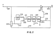
- the output 212 of the direction-of-current detector 203 both is connected both direct and through a memory 230 to an input of an OR-gate 232, the output of which is connected to input 211 of the electronic synchronization signal generator 204.
- the memory 230 preferably has the form of a monostable timing element that returns to the stable non-active state after a certain period of time has lapsed. The certain period of time should minimally correspond with the time period in which errors can arise, practically 15° of a cycle, so that erroneous current zero crossing signals are eliminated.
- the apparatus includes for each of the phases R, S and T a circuit as shown in fig. 2 for phase T.
Landscapes
- Engineering & Computer Science (AREA)
- Power Engineering (AREA)
- Control Of Electrical Variables (AREA)
Applications Claiming Priority (2)
| Application Number | Priority Date | Filing Date | Title |
|---|---|---|---|
| NL8602895 | 1986-11-14 | ||
| NL8602895A NL8602895A (nl) | 1986-11-14 | 1986-11-14 | Inrichting voor het besturen van de voeding van een inductieve belasting. |
Publications (1)
| Publication Number | Publication Date |
|---|---|
| EP0268337A1 true EP0268337A1 (fr) | 1988-05-25 |
Family
ID=19848840
Family Applications (1)
| Application Number | Title | Priority Date | Filing Date |
|---|---|---|---|
| EP87202209A Withdrawn EP0268337A1 (fr) | 1986-11-14 | 1987-11-13 | Dispositif pour commander l'alimentation de puissance d'une charge inductrice |
Country Status (3)
| Country | Link |
|---|---|
| EP (1) | EP0268337A1 (fr) |
| JP (1) | JPS63137310A (fr) |
| NL (1) | NL8602895A (fr) |
Citations (2)
| Publication number | Priority date | Publication date | Assignee | Title |
|---|---|---|---|---|
| US3611097A (en) * | 1970-02-05 | 1971-10-05 | Gen Electric | Digital control system for ac to dc power conversion apparatus |
| FR2339988A1 (fr) * | 1976-01-28 | 1977-08-26 | Borg Warner | Dispositif d'asservissement de l'alimentation d'une charge triphasee |
-
1986
- 1986-11-14 NL NL8602895A patent/NL8602895A/nl not_active Application Discontinuation
-
1987
- 1987-11-13 EP EP87202209A patent/EP0268337A1/fr not_active Withdrawn
- 1987-11-14 JP JP28649187A patent/JPS63137310A/ja active Pending
Patent Citations (2)
| Publication number | Priority date | Publication date | Assignee | Title |
|---|---|---|---|---|
| US3611097A (en) * | 1970-02-05 | 1971-10-05 | Gen Electric | Digital control system for ac to dc power conversion apparatus |
| FR2339988A1 (fr) * | 1976-01-28 | 1977-08-26 | Borg Warner | Dispositif d'asservissement de l'alimentation d'une charge triphasee |
Also Published As
| Publication number | Publication date |
|---|---|
| JPS63137310A (ja) | 1988-06-09 |
| NL8602895A (nl) | 1988-06-01 |
Similar Documents
| Publication | Publication Date | Title |
|---|---|---|
| US4392099A (en) | Starting system for brushless motor | |
| US3694718A (en) | Methods of inverter voltage control by superimposed chopping | |
| EP0231046A3 (en) | Commutation circuit for a collectorless d.c. motor | |
| GB1108571A (en) | Inverter systems | |
| JP2545126B2 (ja) | モ―タ制御装置 | |
| US3652924A (en) | Arrangement for controlling the current of an at least two-phase load with constant frequency supply voltage | |
| CA2187991A1 (fr) | Methode et appareil pour la commande de composants electroniques statiques lors du changement de phase dans un moteur electrique triphase sans collecteur | |
| GB1532031A (en) | Three phase load controlling system | |
| US4422028A (en) | Brushless excitation system with a holding current resistor | |
| US4188659A (en) | Static AC/AC thyristor converter for a self-driven synchronous motor | |
| WO1986004753A1 (fr) | Procede et dispositif de freinage d'un moteur asynchrone | |
| JP3042849B2 (ja) | 3端子パワー半導体デバイスのための制御回路 | |
| RU2133977C1 (ru) | Способ переключения ответвлений обмотки трансформатора и устройство для его осуществления | |
| JPS6460264A (en) | Method and device for controlling voltage type inverter | |
| SU944034A1 (ru) | Электропривод переменного тока | |
| US4926307A (en) | Polyphase a.c. motor supplied with power via d.c. power supply | |
| SU919035A1 (ru) | Устройство дл управлени трехфазным асинхронным двигателем | |
| SU1037403A1 (ru) | Способ управлени асинхронным электродвигателем и устройство дл его осуществлени | |
| JPH0332296B2 (fr) | ||
| SU1585859A1 (ru) | Устройство дл определени пор дка чередовани фазных напр жений сети | |
| SU1709484A1 (ru) | Устройство дл управлени асинхронным электродвигателем | |
| SU1001473A1 (ru) | Ключ переменного тока | |
| SU758518A1 (ru) | Трехфазный коммутатор | |
| SU1099314A1 (ru) | Способ бесконтактной коммутации трехфазной конденсаторной батареи | |
| SU1649686A1 (ru) | Устройство дл импульсного управлени трансформаторной нагрузкой |
Legal Events
| Date | Code | Title | Description |
|---|---|---|---|
| PUAI | Public reference made under article 153(3) epc to a published international application that has entered the european phase |
Free format text: ORIGINAL CODE: 0009012 |
|
| AK | Designated contracting states |
Kind code of ref document: A1 Designated state(s): AT BE CH DE ES FR GB GR IT LI LU NL SE |
|
| STAA | Information on the status of an ep patent application or granted ep patent |
Free format text: STATUS: THE APPLICATION IS DEEMED TO BE WITHDRAWN |
|
| 18D | Application deemed to be withdrawn |
Effective date: 19881128 |
|
| RIN1 | Information on inventor provided before grant (corrected) |
Inventor name: OTTER, HERMAN |