EP0268346A1 - Procédé et dispositif pour la commande du mouvement du clapet de la trémie - Google Patents
Procédé et dispositif pour la commande du mouvement du clapet de la trémie Download PDFInfo
- Publication number
- EP0268346A1 EP0268346A1 EP87304353A EP87304353A EP0268346A1 EP 0268346 A1 EP0268346 A1 EP 0268346A1 EP 87304353 A EP87304353 A EP 87304353A EP 87304353 A EP87304353 A EP 87304353A EP 0268346 A1 EP0268346 A1 EP 0268346A1
- Authority
- EP
- European Patent Office
- Prior art keywords
- hopper
- gate
- program
- hopper gate
- signals
- Prior art date
- Legal status (The legal status is an assumption and is not a legal conclusion. Google has not performed a legal analysis and makes no representation as to the accuracy of the status listed.)
- Granted
Links
- 230000033001 locomotion Effects 0.000 title claims abstract description 30
- 238000000034 method Methods 0.000 title claims description 15
- 238000005303 weighing Methods 0.000 claims abstract description 36
- 230000004044 response Effects 0.000 claims description 5
- 230000001419 dependent effect Effects 0.000 claims 1
- 230000009471 action Effects 0.000 abstract description 5
- 230000007246 mechanism Effects 0.000 description 7
- 238000010586 diagram Methods 0.000 description 3
- 238000007599 discharging Methods 0.000 description 3
- 239000006185 dispersion Substances 0.000 description 3
- 230000008569 process Effects 0.000 description 2
- 230000015572 biosynthetic process Effects 0.000 description 1
- 230000008859 change Effects 0.000 description 1
- 230000001143 conditioned effect Effects 0.000 description 1
- 230000000694 effects Effects 0.000 description 1
- 238000012423 maintenance Methods 0.000 description 1
- 238000005259 measurement Methods 0.000 description 1
- 238000005192 partition Methods 0.000 description 1
Images


Classifications
-
- G—PHYSICS
- G01—MEASURING; TESTING
- G01G—WEIGHING
- G01G19/00—Weighing apparatus or methods adapted for special purposes not provided for in the preceding groups
- G01G19/387—Weighing apparatus or methods adapted for special purposes not provided for in the preceding groups for combinatorial weighing, i.e. selecting a combination of articles whose total weight or number is closest to a desired value
- G01G19/393—Weighing apparatus or methods adapted for special purposes not provided for in the preceding groups for combinatorial weighing, i.e. selecting a combination of articles whose total weight or number is closest to a desired value using two or more weighing units
-
- B—PERFORMING OPERATIONS; TRANSPORTING
- B65—CONVEYING; PACKING; STORING; HANDLING THIN OR FILAMENTARY MATERIAL
- B65D—CONTAINERS FOR STORAGE OR TRANSPORT OF ARTICLES OR MATERIALS, e.g. BAGS, BARRELS, BOTTLES, BOXES, CANS, CARTONS, CRATES, DRUMS, JARS, TANKS, HOPPERS, FORWARDING CONTAINERS; ACCESSORIES, CLOSURES, OR FITTINGS THEREFOR; PACKAGING ELEMENTS; PACKAGES
- B65D90/00—Component parts, details or accessories for large containers
- B65D90/54—Gates or closures
- B65D90/62—Gates or closures having closure members movable out of the plane of the opening
- B65D90/623—Gates or closures having closure members movable out of the plane of the opening having a rotational motion
-
- B—PERFORMING OPERATIONS; TRANSPORTING
- B65—CONVEYING; PACKING; STORING; HANDLING THIN OR FILAMENTARY MATERIAL
- B65D—CONTAINERS FOR STORAGE OR TRANSPORT OF ARTICLES OR MATERIALS, e.g. BAGS, BARRELS, BOTTLES, BOXES, CANS, CARTONS, CRATES, DRUMS, JARS, TANKS, HOPPERS, FORWARDING CONTAINERS; ACCESSORIES, CLOSURES, OR FITTINGS THEREFOR; PACKAGING ELEMENTS; PACKAGES
- B65D90/00—Component parts, details or accessories for large containers
- B65D90/54—Gates or closures
- B65D90/62—Gates or closures having closure members movable out of the plane of the opening
- B65D90/626—Gates or closures having closure members movable out of the plane of the opening having a linear motion
-
- G—PHYSICS
- G01—MEASURING; TESTING
- G01G—WEIGHING
- G01G13/00—Weighing apparatus with automatic feed or discharge for weighing-out batches of material
- G01G13/16—Means for automatically discharging weigh receptacles under control of the weighing mechanism
- G01G13/18—Means for automatically discharging weigh receptacles under control of the weighing mechanism by valves or flaps in the container bottom
-
- B—PERFORMING OPERATIONS; TRANSPORTING
- B65—CONVEYING; PACKING; STORING; HANDLING THIN OR FILAMENTARY MATERIAL
- B65D—CONTAINERS FOR STORAGE OR TRANSPORT OF ARTICLES OR MATERIALS, e.g. BAGS, BARRELS, BOTTLES, BOXES, CANS, CARTONS, CRATES, DRUMS, JARS, TANKS, HOPPERS, FORWARDING CONTAINERS; ACCESSORIES, CLOSURES, OR FITTINGS THEREFOR; PACKAGING ELEMENTS; PACKAGES
- B65D2590/00—Component parts, details or accessories for large containers
- B65D2590/54—Gates or closures
- B65D2590/66—Operating devices therefor
- B65D2590/662—Operating devices therefor allowing a particular motion, e.g. combination of rotational and linear
-
- B—PERFORMING OPERATIONS; TRANSPORTING
- B65—CONVEYING; PACKING; STORING; HANDLING THIN OR FILAMENTARY MATERIAL
- B65D—CONTAINERS FOR STORAGE OR TRANSPORT OF ARTICLES OR MATERIALS, e.g. BAGS, BARRELS, BOTTLES, BOXES, CANS, CARTONS, CRATES, DRUMS, JARS, TANKS, HOPPERS, FORWARDING CONTAINERS; ACCESSORIES, CLOSURES, OR FITTINGS THEREFOR; PACKAGING ELEMENTS; PACKAGES
- B65D2590/00—Component parts, details or accessories for large containers
- B65D2590/54—Gates or closures
- B65D2590/66—Operating devices therefor
- B65D2590/664—Operating devices therefor actuating mechanism other than manual, e.g. pneumatic, electropneumatic, hydraulic, electromagnetic
-
- B—PERFORMING OPERATIONS; TRANSPORTING
- B65—CONVEYING; PACKING; STORING; HANDLING THIN OR FILAMENTARY MATERIAL
- B65D—CONTAINERS FOR STORAGE OR TRANSPORT OF ARTICLES OR MATERIALS, e.g. BAGS, BARRELS, BOTTLES, BOXES, CANS, CARTONS, CRATES, DRUMS, JARS, TANKS, HOPPERS, FORWARDING CONTAINERS; ACCESSORIES, CLOSURES, OR FITTINGS THEREFOR; PACKAGING ELEMENTS; PACKAGES
- B65D2590/00—Component parts, details or accessories for large containers
- B65D2590/54—Gates or closures
- B65D2590/66—Operating devices therefor
- B65D2590/668—Controlling devices
Definitions
- This invention relates to a method of and apparatus for controlling hopper gate motion, and in particular for controlling the motion of hopper gates in a combinational weighing system.
- actuators of many types have been considered for driving the gate or gates of a hopper which receives the product being weighed.
- a flapdoor type gate operated by an air cylinder has been disclosed in US-A-4522321.
- Hoppers of a combinational weighing system which are opened and closed by a motor have been disclosed, for example, in US-A-4497385, US-A-4520884 and US-A-4544042.
- These known actuators are primarily intended merely for opening or closing a hopper gate in response to an input signal. In many situations, actuators of this straightforward operating mode are satisfactory but these are applications for which a finer control of the gate motion is desirable.
- each hopper gate will be opened or closed almost in an identical manner once a signal is given, irrespective of whether the hopper is nearly full and will take a relatively longer time to discharge all its contents or it is nearly empty and hence can be emptied immediately without even opening the gate completely. Given these circumstances, the operations time of a combinational weighing system cannot be substantially reduced.
- a method of controlling the motion of a hopper gate actuated by a driving means characterised by the steps of selecting a mode of opening and closing motion of said hopper gate in terms of positions therof at selected times; forming a program by determining a sequence of signals to be applied to said driving means so as to execute said mode of motion by said hopper gate; and transmitting signals to said driving means according to said program.
- apparatus for controlling the motion of a hopper gate characterised by control means for sequentially transmitting a series of signals according to a program; and driving means for moving said hopper gate by an angle and in a direction determined by and in response to each of said signals.
- a hopper gate can be selectably opened either completely or partially, and the motion of the hopper gate can be such that the gate can close quietly and reduce "slap".
- the hopper gate can be caused to undergo a controlled vibratory motion after it is opened to shake off sticky contents.
- desired motion characteristics such as how gradually the gate should close and whether the gate should be vibrated several times to shake off the sticky contents of the hopper after it is opened, are established in terms of gate positions at selected points in time, it can be determined from the known characteristics of the driving means what signals should be applied to it to cause the desired motion.
- This program can be stored in a memory means and a computer in the control system can execute the program by transmitting signals according thereto to effect the desired motion.
- the driving means is a stepping motor, in which case the signals are pulse signals.
- FIG. 1 is a partially sectional plan view of a hopper-operating mechanism for one of the article batch handling units of a combinational weighing system.
- Figs. 2 and 3 are its side views taken respectively along the lines 2-2 and 3-3 of Fig. 1.
- Numeral 117 indicates a pool hopper for receiving an article batch and discharging it into a weigh hopper 118 therebelow after temporarily holding it.
- the associated weigh hopper 118 is for receiving the article batch discharged from the pool hopper 117 thereabove, measuring its weight and then discharging it.
- Two stepping motors are provided to operate the gates of these hoppers.
- Numeral 61 indicates the shaft of one of these stepping motors which is for operating the gates of the weight hopper 118 and numeral 75 indicates the shaft of the other stepping motor for operating the gates of the pool hopper 117.
- a cam 62 for operating the outer gate of the weight hopper 118 as shown in Fig. 2.
- another cam 63 is secured at the other end of the shaft 61 for operating the inner gate of the weigh hopper 118 as shown in Fig. 3.
- This motion is transmitted to the outer gate of the weigh hopper 118 through a linking member 70, causing it to rotate around its axis of rotation 71.
- the associated stepping motor is rotated in the reverse direction around its shaft 61 to bring the cam 62 back to its original position.
- the cam 62 is caused to rotate, the lever members 65 and 67 are rotated to the left by the force of a spring 72 and the U-shaped lever 68 is rotated to the right by a spring 73.
- the inner gate of the weigh hopper 118 is similarly opened and closed.
- the other stepping motor for operating the gates of the associated pool hopper 117 is provided at one end of its shaft 85 with a cam 86 as shown in Fig. 2.
- the cam 86 pushes a cam follower 87 upwards during the first 180 degree-rotation, causing level members 88 and 89 to rotate in a clockwise direction around its axis of rotation 90.
- Lever members 92 and 94 rotatably connected thereto through a link 91 is thereby caused to rotate around an axis 93 in a counterclockwise direction to push an L-shaped lever 95.
- Numerals 121 and 122 indicate disks provided with a slit attached respectively to the shafts 91 and 85 of the stepping motors so that these slits can be detected by photosensors 125 and 126. They are for the purpose of detecting the initial positions of the shaft 61 and 85. Their positioning is usually not required except, for example, after a runaway situation.
- Numeral 130 indicates a load cell.
- Fig. 4 is a block diagram of an apparatus embodying the present invention for controlling the operation of a hopper gate.
- the hopper 10 is powered by a stepping motor (also called a pulse motor or a stepper motor) 12 which, for example, may be Model PH268-21B manufactured by Oriental Motor Kabushiki Kaisha of Osaka, Japan or Model PH299-03B by the same manufacturer and used in the combiantional weighing machine Model CCW-L manufactured and sold by us and described in EP-A-0219347.
- a stepping motor also called a pulse motor or a stepper motor
- the motor 12 is operated by pulses provided through a driver means 16 according to a program stored in a computer 20.
- a program stored in a computer 20.
- the program is written as a time sequence of pulses to be provided to the motor 12 and for this and other reasons, a timer 22 is also controlled by the computer 20 and the computer 20, in turn, executes the program by making reference to the timer output.
- a control panel 24 including a key input device and a display device is connected to the computer 20.
- step motor 12 is so designed that the hopper gate comes to a half-open position after the motor 12 is driven for 100 pulses and that the gate becomes fully open with 200 pulses. If it is desired to operate the motor 12 to open and close the hopper 10, for example, as shown by a solid line in Fig.
- the motor 12 starts abruptly and turns at a constant rate for a first time period t1 (such as 60ms), then gradually decelerates for a second time period t2 (such as 30ms) until the gate comes to the half-open position, then remains stationary for a third time period t3 (such as 80ms) with the gate at the half-open position, then gradually accelerates in the reverse direction for a fourth period of time t4 (such as 30ms), then rotates in the reverse direction at a constant rate for a fifth period of time t5 (such as 50ms) and then gradually decelerates from this reverse rotation for a sixth period t6 (such as 50ms) until the gate closes completely to complete a cycle of operation over a total period of 300ms.
- a similar program may of course be considered for opening the gate completely and then bringing it to the closed position quietly as indicated by a dotted line in Fig. 5.
- Table 1 On the basis of the desired mode of operation described above and indicated by the solid line in Fig. 5, one can prepare a program as shown in Table 1 for transmitting pulses to the motor 12.
- the first line of Table 1 shows, for example, that during the aforementioned first time period t1, the motor is rotated in the direction defined to be positive while the timer 22 counts 89 pulses of period 0.67ms.
- the following four lines in Table 1 describe how the deceleration in the second period t2 is effected, that is, the deceleration is not uniform but is carried out as a series of four constant-speed motions.
- T i , P i and F i respectively representing the pulse period, the number of pulses and the direction of rotation in the ith period of operation are stored in the computer 20 through the input-output means 24.
- the computer 20 then asks the user, advantageously by writing questions on the display means (not shown), how wide the gate should be opened (for example, 100% for opening completely and 50% for opening to the half-open position) and how long it should take to open and close the gate (for example, 100% for a cycle with the aforementioned period of 300ms as shown in Fig. 5).
- the computer 20 creates a working program on the basis of Table 1 by multiplying P i of Table 1 by 2 and dividing T i of Table 1 by 2. If the user wants to open the gate 75% with the same period of time, T i of Table 1 are likewise multiplied by 3/4 and P i by 4/3. If it is desired to double the period and the user responds with 200% to the second question, the computer 20 multiplies T i by 2 with P i remaining unchanged. After the working program is thus created, incorporating the input by the user, the computer 20 stores it in its memory means and causes the driver means 16 to operate the step motor 12 according to this stored working program.
- the stepping motor can be controlled by a variety of programs, for example the gate can be opened as quickly as possible, for example, to increase the speed of discharge. Otherwise, the gate can be exponentially accelerated and decelerated at the beginning and end so of its motion as to reduce the noise of impact caused by sudden movements.
- the gate When sticky articles are being handled by the hopper it may be found advantageous to cause the gate to execute a vibratory motion with a small amplitude over a predetermined short period of time after the gate has been opened. This can be accomplished by reversing the direction of rotation of the step motor a predetermined number of times to move the gate back and forth.
- Fig. 8 shows an example of combinational weighing system 210 which can utilize the method and apparatus of the present invention.
- Combinational weighing means weighing articles by a plurality of weighing devices, performing arithmetic operations for combinations of measured weight values and then selecting a combination according to a predetermined criterion.
- the major features of combinational weighing are great accuracy and high throughput.
- the articles to be weighed are transported by a conveyor means (not shown) and dropped onto a dispersion table 212 which is a circular table with a lightly inclined conical top surface so that the articles dropped thereonto from the conveyor means can be made to disperse uniformly in radial directions.
- a plurality of feed troughs 213 each with an article receiving end and an article delivering end are arranged in a circular formation around the dispersion table 212 with their article receiving ends adjacent thereto.
- Both the dispersion table 212 and the feed troughs 213 are supported on a system housing 215 preferably through individual vibration-causing means (not shown) which serve to cause vibrational motion of the articles thereon.
- the feed troughs 213 are disposed radially and serve to deliver the articles to be weighed into the individual article batch handling units associated therewith.
- Each article batch handling unit includes a pool hopper 217 serving to receive an article batch from the feed trough 213 associated with the article batch handling unit to which it belongs and to discharge the same article batch into a weigh hopper 218 belonging to the same article batch handling unit and situated immediately therebelow.
- Each weigh hopper 218 is connected to a weighing device (not shown) such as a load cell and serves momentarily to hold the article batch received from the pool hopper 217 thereabove.
- the weight values measured by the load cells are electrically transmitted to a control unit (not shown) which includes a computer.
- the lower part of the system 210 is comprised of a chute assembly.
- the chute assembly includes a funnel-shaped outer chute 220 coaxially surrounding a funnel-shaped inner chute 221 in such a way that they form two separate discharge routes.
- the outer chute 220 is divided into two separate passages where it is connected to left-hand and right-hand timing hoppers 224 which are, in turn, connected to a lower chute 225 so that the articles discharged into the outer chute 220 join together.
- At the bottom of the inner chute 221 is provided another timing hopper 227 which is connected to a second lower chute 228.
- one program may be established for all hoppers or the system may be so designed that the hoppers can be programmed individually.
- the hoppers are identified, for example, by different indentification numbers and the user is requested to specify an identification number in addition to how wide its gate should be opened and how long it should take to open and close the gate as described above.
- a lever or the like for actually communicating the gate-opening force from the stepping motor 12 to the hopper gate must be separated from the hopper during the weighing process, or when the gate is completely closed as illustrated, for example, in Fig. 6 of the aforementioned US-A-4520884.
- a predetermined clearance therefore, is left between such a lever and a roller or the like on which the lever applies a force to open the gate. For this reason, there is generally a delay between the time when a command signal is received for opening the gate and the time at which the lever comes in contact with the roller and the gate actually begins to open.
- the stepping motor associated with the hopper can start opening its gate without any delay because the lever is already in contact with the roller.
- the stepping motor is rotated in the reverse direction to separate the lever from the roller by a predetermined distance such that the hopper is ready for the next weighing operation.
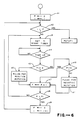
- FIG. 7 is an illustrative flow chart for the aforementioned operation of a weigh hopper. While the weighing takes place (NO in n21), the control system is engaged in other operations (n22) but as soon as the weighing is completed, the stepping motor is rotated by a predetermined number of steps until the lever touches the roller without opening the gate (n23). Thereafter, the system waits for a drive signal (n24).
- the gate is opened to discharge the articles contained therein and then is closed according to the program shown in Fig. 3 or Table 1 (n26). If the hopper was not selected and did not receive a discharge signal (NO in n25), the stepping motor is rotated in the reverse direction to separate the lever from the roller (n27).
- the timer 22 may be an external timer rather than an internal software time. If it is an external timer, Step n4 of Fig. 6 will be replaced by an interrupt.
- Additional advantages of the method and apparatus of the invention include adjustability of the maximum angle to which a gate is opened, depending on the amount of articles contained in the hopper. As a result, the speed of weighing can be freely changed according to the amount of supplied articles. Since the motion characteristics of the gate can be easily changed through an input device, there is increased freedom in the design and all kinds of articles can be supplied and discharged in manners best suited for their individual characteristics. When sticky articles are being handled, as mentioned above, the gate can be made to vibrate after it is opened such that errors in measurement caused by articles which failed to be discharged can be usually eliminated.
- the method and apparatus of the invention are conveniently utilized in the type of combinational weighing programs where different hoppers discharge at different times, as disclosed in US-A-4460880, or where the article supplying section is separated into partitions such that different kinds of articles to be weighed are supplied as disclosed in US-A-4549617. Since each action mode of the gate can be stored in memory means as data, many programs representing different action modes, each suited to a particular type of article to be weighed, can be stored such that the user can select the best mode of action, depending on the conditions such as the target weight, and call the corresponding program to operate the hopper gates as shown in US-A-4553616.
Landscapes
- Physics & Mathematics (AREA)
- General Physics & Mathematics (AREA)
- Engineering & Computer Science (AREA)
- Mechanical Engineering (AREA)
- Weight Measurement For Supplying Or Discharging Of Specified Amounts Of Material (AREA)
- Filling Or Emptying Of Bunkers, Hoppers, And Tanks (AREA)
Applications Claiming Priority (2)
| Application Number | Priority Date | Filing Date | Title |
|---|---|---|---|
| US06/931,218 US4705125A (en) | 1986-11-14 | 1986-11-14 | Method of and apparatus for controlling hopper gate motion |
| US931218 | 1986-11-14 |
Publications (2)
| Publication Number | Publication Date |
|---|---|
| EP0268346A1 true EP0268346A1 (fr) | 1988-05-25 |
| EP0268346B1 EP0268346B1 (fr) | 1991-06-26 |
Family
ID=25460410
Family Applications (1)
| Application Number | Title | Priority Date | Filing Date |
|---|---|---|---|
| EP87304353A Expired - Lifetime EP0268346B1 (fr) | 1986-11-14 | 1987-05-15 | Procédé et dispositif pour la commande du mouvement du clapet de la trémie |
Country Status (4)
| Country | Link |
|---|---|
| US (1) | US4705125A (fr) |
| EP (1) | EP0268346B1 (fr) |
| AU (1) | AU600718B2 (fr) |
| DE (1) | DE3771036D1 (fr) |
Cited By (2)
| Publication number | Priority date | Publication date | Assignee | Title |
|---|---|---|---|---|
| EP0677723A1 (fr) * | 1994-04-13 | 1995-10-18 | Optima-Maschinenfabrik Dr. Bühler GmbH & Co. | Balance de remplissage |
| ES2220172A1 (es) * | 2002-04-24 | 2004-12-01 | Payper, S.A. | Dispositivo de cierre para el control de flujo de material en una maquina pesadora. |
Families Citing this family (21)
| Publication number | Priority date | Publication date | Assignee | Title |
|---|---|---|---|---|
| GB8705451D0 (en) * | 1987-03-09 | 1987-04-15 | Driver Southall | Combinational weighing systems |
| US4947946A (en) * | 1988-09-14 | 1990-08-14 | Ishida Scales Mfg. Co. Ltd. | Hopper gate opening and closing device for an automatic weighing apparatus |
| US5234128A (en) * | 1991-05-13 | 1993-08-10 | Hill Francis K | Aggregate material spreader |
| US5324894A (en) * | 1993-03-01 | 1994-06-28 | Industrial Technology Research Institute | Multiple weighing apparatus for mass materials with dual-acting hopper gates mechanism |
| IT1278216B1 (it) * | 1995-05-22 | 1997-11-17 | Bl Macchine Automatiche | Dispositivo di dosaggio perfezionato per l'alimentazione di bilance |
| US5736683A (en) * | 1996-03-15 | 1998-04-07 | Kliklok Corporation | Multiple hopper weighing and transfer system |
| US6188029B1 (en) * | 1996-07-03 | 2001-02-13 | Ishida Co., Ltd. | Weighing apparatus having improved hopper detachability |
| US6161986A (en) * | 1998-06-12 | 2000-12-19 | Geff's Manufacturing, Inc. | Aggregate spreading apparatus and methods |
| JP3785090B2 (ja) * | 2001-12-13 | 2006-06-14 | 株式会社イシダ | 組合せ計量装置 |
| EP1319932A3 (fr) | 2001-12-13 | 2006-12-20 | Ishida Co., Ltd. | Dispositif de pesage combinatoire |
| NO321274B1 (no) * | 2004-09-24 | 2006-04-10 | Tomra Systems Asa | Anordning for forflytning av gjenstander |
| JP4630074B2 (ja) * | 2005-01-24 | 2011-02-09 | 大和製衡株式会社 | 組合せ秤 |
| US7889401B2 (en) * | 2006-06-01 | 2011-02-15 | Marvell International Ltd. | Floating scan sensor in a multi-function printer |
| ITMI20080950A1 (it) * | 2008-05-22 | 2009-11-23 | Ilapak Internat S A | Apparecchio di pesatura automatica a cestelli |
| BRPI0904660A2 (pt) * | 2009-11-04 | 2011-11-16 | Whirlpool Sa | dispensador de gelo motorizado para refrigeradores |
| CN103052869B (zh) * | 2011-04-05 | 2014-08-27 | 大和制衡株式会社 | 料斗闸门开闭机构 |
| JP6279355B2 (ja) * | 2014-03-07 | 2018-02-14 | 大和製衡株式会社 | 組合せ秤 |
| US10640288B2 (en) * | 2015-07-22 | 2020-05-05 | Halliburton Energy Services, Inc. | Rotary clamshell gate actuator for bulk material container |
| CA2996055C (fr) | 2015-11-25 | 2022-04-26 | Halliburton Energy Services, Inc. | Sequencage de contenants de matieres en vrac pour une utilisation de materiau continue |
| JP7340246B2 (ja) * | 2019-10-07 | 2023-09-07 | 株式会社イシダ | 計量装置 |
| JP7606205B2 (ja) * | 2020-11-06 | 2024-12-25 | 株式会社イシダ | 組合せ計量装置 |
Citations (6)
| Publication number | Priority date | Publication date | Assignee | Title |
|---|---|---|---|---|
| US3511412A (en) * | 1967-01-17 | 1970-05-12 | Courtaulds Ltd | Apparatus for discharging particulate material |
| US4494619A (en) * | 1982-06-23 | 1985-01-22 | Kabushiki Kaisha Ishida Koki Seisakusho | Combinatorial weighing apparatus with bulk and fine feed |
| US4497385A (en) * | 1981-08-18 | 1985-02-05 | Kabushiki Kaisha Ishida Koki Seisakusho | Combinatorial weighing apparatus |
| EP0140213A1 (fr) * | 1983-10-06 | 1985-05-08 | Bühler AG | Procédé et dispositif pour mesurer le débit de matériaux susceptibles de couler |
| US4548287A (en) * | 1982-07-31 | 1985-10-22 | Teraoka Seiko Co., Ltd. | Combination weighing machine with vibratory feeding and collecting hopper |
| EP0171291A2 (fr) * | 1984-08-08 | 1986-02-12 | Ishida Scales Mfg. Co. Ltd. | Dispositif pour ouvrir et fermer des trémies |
Family Cites Families (8)
| Publication number | Priority date | Publication date | Assignee | Title |
|---|---|---|---|---|
| US1829182A (en) * | 1926-05-06 | 1931-10-27 | Beaumont Mfg Company | Hopper gate actuating mechanism |
| US2723058A (en) * | 1951-04-13 | 1955-11-08 | Houdaille Hershey Of Indiana I | Snubber device for a weighing hopper in a fiber handling machine |
| US3581947A (en) * | 1969-01-27 | 1971-06-01 | Iowa Mfg Co | Linearized gate control system for multiple feeder and hopper arrangements |
| US4193465A (en) * | 1978-01-27 | 1980-03-18 | The Woodman Company, Inc. | Scale hopper door mechanism |
| JPS57141753A (en) * | 1981-02-25 | 1982-09-02 | Nec Corp | Multiplication circuit |
| AU565443B2 (en) * | 1982-10-01 | 1987-09-17 | K.K. Ishida Koki Seisakusho | Hopper for combination weigher |
| JPS5974092A (ja) * | 1982-10-05 | 1984-04-26 | 大和製衡株式会社 | ゲ−ト開閉装置 |
| US4544042A (en) * | 1983-11-08 | 1985-10-01 | Kabushiki Kaisha Ishida Koki Seisakusho | Hopper door actuating apparatus for an automatic weighing apparatus |
-
1986
- 1986-11-14 US US06/931,218 patent/US4705125A/en not_active Expired - Lifetime
-
1987
- 1987-04-16 AU AU71766/87A patent/AU600718B2/en not_active Expired
- 1987-05-15 DE DE8787304353T patent/DE3771036D1/de not_active Expired - Lifetime
- 1987-05-15 EP EP87304353A patent/EP0268346B1/fr not_active Expired - Lifetime
Patent Citations (6)
| Publication number | Priority date | Publication date | Assignee | Title |
|---|---|---|---|---|
| US3511412A (en) * | 1967-01-17 | 1970-05-12 | Courtaulds Ltd | Apparatus for discharging particulate material |
| US4497385A (en) * | 1981-08-18 | 1985-02-05 | Kabushiki Kaisha Ishida Koki Seisakusho | Combinatorial weighing apparatus |
| US4494619A (en) * | 1982-06-23 | 1985-01-22 | Kabushiki Kaisha Ishida Koki Seisakusho | Combinatorial weighing apparatus with bulk and fine feed |
| US4548287A (en) * | 1982-07-31 | 1985-10-22 | Teraoka Seiko Co., Ltd. | Combination weighing machine with vibratory feeding and collecting hopper |
| EP0140213A1 (fr) * | 1983-10-06 | 1985-05-08 | Bühler AG | Procédé et dispositif pour mesurer le débit de matériaux susceptibles de couler |
| EP0171291A2 (fr) * | 1984-08-08 | 1986-02-12 | Ishida Scales Mfg. Co. Ltd. | Dispositif pour ouvrir et fermer des trémies |
Non-Patent Citations (1)
| Title |
|---|
| ENGINEERING, vol. 223, no. 10, October 1983, page 792, London, GB; "Electronically-controlled hopper copes with sticky materials" * |
Cited By (3)
| Publication number | Priority date | Publication date | Assignee | Title |
|---|---|---|---|---|
| EP0677723A1 (fr) * | 1994-04-13 | 1995-10-18 | Optima-Maschinenfabrik Dr. Bühler GmbH & Co. | Balance de remplissage |
| US5667108A (en) * | 1994-04-13 | 1997-09-16 | Optima-Maschinenfabrik Dr. Buhler Gmbh & Co. | Single valve dispensing balance |
| ES2220172A1 (es) * | 2002-04-24 | 2004-12-01 | Payper, S.A. | Dispositivo de cierre para el control de flujo de material en una maquina pesadora. |
Also Published As
| Publication number | Publication date |
|---|---|
| US4705125A (en) | 1987-11-10 |
| EP0268346B1 (fr) | 1991-06-26 |
| AU600718B2 (en) | 1990-08-23 |
| AU7176687A (en) | 1988-05-19 |
| DE3771036D1 (de) | 1991-08-01 |
Similar Documents
| Publication | Publication Date | Title |
|---|---|---|
| EP0268346B1 (fr) | Procédé et dispositif pour la commande du mouvement du clapet de la trémie | |
| US4560015A (en) | Combinatorial weighing apparatus | |
| US4807711A (en) | Weighing hoppers | |
| US4844190A (en) | Combinational weigher for multiple operations | |
| US4708215A (en) | Automatic weighing system | |
| US4497385A (en) | Combinatorial weighing apparatus | |
| CA1256906A (fr) | Methode et appareil de pesage pour combinaisons de masses | |
| USRE32276E (en) | Combinatorial weighing system with discharge control | |
| EP1174693B1 (fr) | Mécanisme d'attribution pour un dispositif de pesage | |
| US6000200A (en) | Bagging apparatus | |
| US4553617A (en) | Article discharge apparatus in automatic weighing system | |
| US6271485B1 (en) | Article alignment device | |
| US4498665A (en) | Paper sorting/storing apparatus | |
| JP4129997B2 (ja) | 産物準備供給システムのための産物供給装置 | |
| JPS63127124A (ja) | 計量装置 | |
| EP0181738B1 (fr) | Appareil de commande de débit | |
| EP0139104B1 (fr) | Dispositif de mesurage combinatoire | |
| RU2775198C1 (ru) | Весовой комбинационный дозатор | |
| EP0307188A2 (fr) | Collection d'articles pesés | |
| RU12241U1 (ru) | Система дозирования | |
| JPH0127063Y2 (fr) | ||
| US579449A (en) | richards | |
| SU1597307A1 (ru) | Способ дозировани вещества и устройство дл его осуществлени | |
| SU712682A1 (ru) | Весовой дозатор непрерывного действи | |
| JP2024167826A (ja) | 組合せ計量装置 |
Legal Events
| Date | Code | Title | Description |
|---|---|---|---|
| PUAI | Public reference made under article 153(3) epc to a published international application that has entered the european phase |
Free format text: ORIGINAL CODE: 0009012 |
|
| AK | Designated contracting states |
Kind code of ref document: A1 Designated state(s): DE FR GB IT |
|
| 17P | Request for examination filed |
Effective date: 19880826 |
|
| 17Q | First examination report despatched |
Effective date: 19900316 |
|
| GRAA | (expected) grant |
Free format text: ORIGINAL CODE: 0009210 |
|
| ITF | It: translation for a ep patent filed | ||
| AK | Designated contracting states |
Kind code of ref document: B1 Designated state(s): DE FR GB IT |
|
| REF | Corresponds to: |
Ref document number: 3771036 Country of ref document: DE Date of ref document: 19910801 |
|
| ET | Fr: translation filed | ||
| PLBE | No opposition filed within time limit |
Free format text: ORIGINAL CODE: 0009261 |
|
| STAA | Information on the status of an ep patent application or granted ep patent |
Free format text: STATUS: NO OPPOSITION FILED WITHIN TIME LIMIT |
|
| 26N | No opposition filed | ||
| REG | Reference to a national code |
Ref country code: GB Ref legal event code: IF02 |
|
| REG | Reference to a national code |
Ref country code: GB Ref legal event code: 732E |
|
| PGFP | Annual fee paid to national office [announced via postgrant information from national office to epo] |
Ref country code: GB Payment date: 20060510 Year of fee payment: 20 |
|
| PGFP | Annual fee paid to national office [announced via postgrant information from national office to epo] |
Ref country code: DE Payment date: 20060511 Year of fee payment: 20 |
|
| PGFP | Annual fee paid to national office [announced via postgrant information from national office to epo] |
Ref country code: FR Payment date: 20060515 Year of fee payment: 20 |
|
| PGFP | Annual fee paid to national office [announced via postgrant information from national office to epo] |
Ref country code: IT Payment date: 20060531 Year of fee payment: 20 |
|
| REG | Reference to a national code |
Ref country code: GB Ref legal event code: PE20 |
|
| PG25 | Lapsed in a contracting state [announced via postgrant information from national office to epo] |
Ref country code: GB Free format text: LAPSE BECAUSE OF EXPIRATION OF PROTECTION Effective date: 20070514 |
|
| REG | Reference to a national code |
Ref country code: DE Ref legal event code: R097 Ref document number: 3771036 Country of ref document: DE Ref country code: DE Ref legal event code: R040 Ref document number: 3771036 Country of ref document: DE |
|
| REG | Reference to a national code |
Ref country code: DE Ref legal event code: R040 Ref document number: 3771036 Country of ref document: DE Effective date: 20120618 |