EP0268358A1 - Soupape de commande pour liquides en écoulement - Google Patents
Soupape de commande pour liquides en écoulement Download PDFInfo
- Publication number
- EP0268358A1 EP0268358A1 EP87308353A EP87308353A EP0268358A1 EP 0268358 A1 EP0268358 A1 EP 0268358A1 EP 87308353 A EP87308353 A EP 87308353A EP 87308353 A EP87308353 A EP 87308353A EP 0268358 A1 EP0268358 A1 EP 0268358A1
- Authority
- EP
- European Patent Office
- Prior art keywords
- chamber
- fluid
- pressure
- membrane
- control
- Prior art date
- Legal status (The legal status is an assumption and is not a legal conclusion. Google has not performed a legal analysis and makes no representation as to the accuracy of the status listed.)
- Withdrawn
Links
- 239000012530 fluid Substances 0.000 title claims description 61
- 239000012528 membrane Substances 0.000 claims abstract description 56
- XLYOFNOQVPJJNP-UHFFFAOYSA-N water Substances O XLYOFNOQVPJJNP-UHFFFAOYSA-N 0.000 claims abstract description 55
- 230000008859 change Effects 0.000 claims description 9
- 230000004044 response Effects 0.000 claims description 5
- 238000006073 displacement reaction Methods 0.000 claims description 4
- 230000003247 decreasing effect Effects 0.000 claims description 3
- 238000007789 sealing Methods 0.000 claims description 3
- 238000004891 communication Methods 0.000 claims description 2
- 230000000694 effects Effects 0.000 description 8
- 239000007788 liquid Substances 0.000 description 4
- 230000009467 reduction Effects 0.000 description 4
- 230000009471 action Effects 0.000 description 2
- 230000000994 depressogenic effect Effects 0.000 description 2
- 230000035945 sensitivity Effects 0.000 description 2
- DHKHKXVYLBGOIT-UHFFFAOYSA-N acetaldehyde Diethyl Acetal Natural products CCOC(C)OCC DHKHKXVYLBGOIT-UHFFFAOYSA-N 0.000 description 1
- 229920001577 copolymer Polymers 0.000 description 1
- 230000008878 coupling Effects 0.000 description 1
- 238000010168 coupling process Methods 0.000 description 1
- 238000005859 coupling reaction Methods 0.000 description 1
- 230000001419 dependent effect Effects 0.000 description 1
- 239000007789 gas Substances 0.000 description 1
- 230000005484 gravity Effects 0.000 description 1
- 238000004519 manufacturing process Methods 0.000 description 1
- 230000007246 mechanism Effects 0.000 description 1
- 229920006343 melt-processible rubber Polymers 0.000 description 1
- 239000000203 mixture Substances 0.000 description 1
- 230000004048 modification Effects 0.000 description 1
- 238000012986 modification Methods 0.000 description 1
- 229920003031 santoprene Polymers 0.000 description 1
- 238000000926 separation method Methods 0.000 description 1
Images


Classifications
-
- G—PHYSICS
- G05—CONTROLLING; REGULATING
- G05D—SYSTEMS FOR CONTROLLING OR REGULATING NON-ELECTRIC VARIABLES
- G05D7/00—Control of flow
- G05D7/01—Control of flow without auxiliary power
- G05D7/0106—Control of flow without auxiliary power the sensing element being a flexible member, e.g. bellows, diaphragm, capsule
-
- Y—GENERAL TAGGING OF NEW TECHNOLOGICAL DEVELOPMENTS; GENERAL TAGGING OF CROSS-SECTIONAL TECHNOLOGIES SPANNING OVER SEVERAL SECTIONS OF THE IPC; TECHNICAL SUBJECTS COVERED BY FORMER USPC CROSS-REFERENCE ART COLLECTIONS [XRACs] AND DIGESTS
- Y10—TECHNICAL SUBJECTS COVERED BY FORMER USPC
- Y10T—TECHNICAL SUBJECTS COVERED BY FORMER US CLASSIFICATION
- Y10T137/00—Fluid handling
- Y10T137/7722—Line condition change responsive valves
- Y10T137/7781—With separate connected fluid reactor surface
- Y10T137/7782—With manual or external control for line valve
-
- Y—GENERAL TAGGING OF NEW TECHNOLOGICAL DEVELOPMENTS; GENERAL TAGGING OF CROSS-SECTIONAL TECHNOLOGIES SPANNING OVER SEVERAL SECTIONS OF THE IPC; TECHNICAL SUBJECTS COVERED BY FORMER USPC CROSS-REFERENCE ART COLLECTIONS [XRACs] AND DIGESTS
- Y10—TECHNICAL SUBJECTS COVERED BY FORMER USPC
- Y10T—TECHNICAL SUBJECTS COVERED BY FORMER US CLASSIFICATION
- Y10T137/00—Fluid handling
- Y10T137/7722—Line condition change responsive valves
- Y10T137/7781—With separate connected fluid reactor surface
- Y10T137/7793—With opening bias [e.g., pressure regulator]
- Y10T137/7796—Senses inlet pressure
-
- Y—GENERAL TAGGING OF NEW TECHNOLOGICAL DEVELOPMENTS; GENERAL TAGGING OF CROSS-SECTIONAL TECHNOLOGIES SPANNING OVER SEVERAL SECTIONS OF THE IPC; TECHNICAL SUBJECTS COVERED BY FORMER USPC CROSS-REFERENCE ART COLLECTIONS [XRACs] AND DIGESTS
- Y10—TECHNICAL SUBJECTS COVERED BY FORMER USPC
- Y10T—TECHNICAL SUBJECTS COVERED BY FORMER US CLASSIFICATION
- Y10T137/00—Fluid handling
- Y10T137/7722—Line condition change responsive valves
- Y10T137/7781—With separate connected fluid reactor surface
- Y10T137/7835—Valve seating in direction of flow
- Y10T137/7836—Flexible diaphragm or bellows reactor
Definitions
- the present invention relates to fluid flow control apparatus.
- British patent specification No. 2,124,338 discloses pillar tap incorporating a fluid flow control system in which the pressure of water is used to assist the opening and closing of the tap.
- an isolated chamber is provided with an opening in which is mounted a flexible diaphragm carrying a valve member for controlling the flow of water from the tap.
- a valve member for controlling the flow of water from the tap.
- the gap between the valve member and valve seat will remain substantially constant and any fluctuation in the pressure of water supplied to the tap will be manifest by a change in the rate of flow of water from the tap. If the water in the sealed chamber contains entrained air bubbles then the gap between the valve member and the valve seat will vary with changes in water pressure but in such a sense as to amplify the changes in flow rate. Such fluctuations in flow rate are undesirable particularly when the tap forms one of a pair of taps used in a hot and cold water mixing arrangement.
- fluid flow control apparatus comprising a valve seat defining an outlet port, a valve member supported by a membrane for movement towards and away from the valve seat to control the flow of fluid through the port, means for supplying fluid under pressure to the valve member over a part of the face of the valve member not shielded by the valve seat, first control means responsive to a command, to vary the pressure on the opposite side of the membrane so as to allow the fluid pressure on the one side of the membrane to displace the valve member away from the valve seat by a predetermined extent to achieve a predetermined flow from the port, and second control means responsive to variations of pressure in the fluid supplied to the port to adjust the pressure on the said opposite side of the diaphragm in a sense and by an amount to tend to maintain the rate of flow from the outlet substantially constant over a predetermined
- fluid flow control apparatus comprising a base member having an upstanding skirt, an inverted cup-shaped member in nested engagement with the skirt of the base member to define with the base member an enclosed chamber, the floor of the base member within the enclosed chamber defining an inlet and a valve seat, said valve seat forming an outlet, a membrane covering said inlet and said outlet and carrying a valve member so positioned as to be movable into and out of engagement with the valve seat in response to displacement of the membrane towards and away from the said floor, a cup-shaped member having a base mounted to urge said membrane against said floor, the base of the cup-shaped member having an opening to allow an area of the membrane extending over at least said inlet and said outlet, freedom to move towards and away from said floor in response to differential pressure across said membrane to control the flow of fluid from the inlet to the outlet, a carrier located in said cup-shaped member and supporting a resilient diaphragm in sliding and sealing engagement with the inner wall of the cup-
- fluid flow control apparatus comprising a main fluid flow chamber having a fluid inlet and a fluid outlet, a fluid control chamber housed within the main chamber, a membrane rigidly supported by the control chamber, adjacent to the fluid outlet, a valve member supported by the membrane for movement along a path into and out of engagement with the fluid outlet, a stretchable elastic diaphragm of greater surface area than the unshielded area of the membrane, the diaphragm forming part of the wall of the control chamber and being subject to pressure by fluid in the main chamber and means for increasing and decreasing the pressure within the control chamber to allow the pressure difference exerted on the membrane by the fluid in the main chamber on the one hand and the fluid in the control chamber on the other hand, to move the valve to and from the outlet whereby any pressure change in the fluid in the main chamber will cause a corresponding change in pressure in the control chamber through the diaphragm which change in pressure in conjunction with the resilience of the diaphragm will move the valve in a sense to maintain the flow of
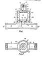
- Figures 1 to 4 show one embodiment of a valve incorporating a flow stabilser arrangement.
- valve has an inlet conduit 50 leading to a control chamber 51, a valve seat 54 in a housing 52 defining the control chamber 51 and an outlet conduit 56 leading from the valve seat 54.
- an elongate closed container 58 filled with an incompressible liquid 60 for example water or oil.
- the lower rim of the container 58 is supported on a land 66 in the bottom of the chamber 51, which land 66 extends generally about the valve seat 54 (see Figure 4).
- the underside of the container 58 is closed by a flexible membrane 62 which in turn supports a centrally located valve member 64 for vertical movement.
- the vertical axis of movement of the valve member 64 is in alignment with the axis of the valve seat 54.
- the roof 68 of the container 58 is of undulating profile to allow it to flex more readily.
- a rigid rod 70 is attached to a central portion of the roof 68 and passes through an opening in the roof of the housing 52.
- An 0-ring 72 is provided to provide a water tight seal between the rod 70 and the housing 52 at the point at which the rod 70 passes through the housing 52.
- the housing 52 carries a frame 71 on which a stem 73 is screwthreadedly supported.
- the stem 73 carries a lower abutment 75 which engages the rod 70 to effect displacement of the rod 70.
- the upper end of the stem 73 carries a handle 77 for effecting rotation of the stem 73.
- the container 58 has four side walls; one pair of opposite walls 58A and 58C being of arcuate configuration and conforming to the inner surface of the housing 52 to hold the container rigidly in position within the chamber 51, a third wall 58B being planar, and a fourth wall 58D being of undulating profile so as to enable it to flex more readily.
- the container 58 is of an acetal copolymer and is such that upon flexure of any wall it will resile.
- the membrane 62 is made of a melt-processable elastomer for example Santoprene (Registered Trade Mark) having little or no resilience.
- the profiles of the container 58 and the chamber 51 are such that water entering the inlet conduit 50 will pass through the gap between the wall 58D and the housing 52, over the roof 68 of the container, through the gap between the wall 58B and the housing 52 to the underside of the membrane 62.
- water will then flow through the valve seat and out along the outlet conduit 56.
- valve member 64 To open the valve member 64 the stem 73 is lifted to raise the rod 70. This will pull the roof 68 upwardly increasing the volume inside the upper portion of the container 58. This now allows the pressure on the underside of the unshielded part of the membrane to displace the valve member 64 upwardly thus releasing water from the chamber 51 into the outlet conduit 56.
- valve member 64 The extent of upward movement of the valve member 64 will depend upon the extend to which the volume in the upper part of the chamber has been increased and this in turn will depend upon the upward movement of the rod 70. Thus the flow rate through the valve will vary as a function of the displacement of the rod 70.
- the flow rate will remain constant so long as the pressure of the water in the inlet conduit 50 remains constant. If the pressure were to increase the flow rate would tend to increase and vice versa.
- the undulating wall 58d acts to compensate for variations in pressure.
- the undulating wall 58d is arranged to have a greater surface area than that of the unshielded part of the membrane 62 and thus if the pressure inside the chamber rises, the wall 58d will be bowed inwardly by this increase in pressure and the displaced liquid in the container 58 will act on the membrane 62 to displace the membrane 62 downwardly.
- the rod 70 may be coupled to any conventional water control mechanism, for example that which is found in a conventional tap.
- valve is particularly advantageous in situations where two sources of water (eg one hot and one cold) are mixed together. Thus if one such valve is used to control the hot water and the similar valve used to control the cold water then once the mixture ratio has been set it will be maintained substantially constant.
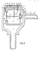
- the domestic pillar tap shown in Figure 5 includes a stem 1 through which water under pressure is supplied into a main chamber 4 within the tap.
- the main chamber 4 has a valve seat 8 which leads to an outlet port 6 from which water from the main chamber 4 will discharge.
- control chamber 10 Supported within the main chamber 4 is a control chamber 10.
- the control chamber 10 has an opening opposite the valve seat which supports a flexible membrane 12 carrying a valve member 14.
- the membrane 12 supports the valve member 14 for movement along a path into and out of engagement with the valve seat 8. If the pressures within the two chambers 4 and 10 are equal there will be a net force acting on the valve member 14 to urge it into engagement with the valve seat 8. This is because a greater area of the membrane 12 and valve member 14 is exposed to the pressure from the control chamber 10 than the area of the -diaphragm and valve member which is exposed to the pressure from the main chamber 4.
- the control chamber 10 communicates with an ante-chamber 11 which in turn communicates with the main chamber 4 through a valve 15.
- the valve 15 includes a valve member 16 which is biassed downwardly by gravity (under its own weight) into an open state.
- a control valve 22 in a wall of the control chamber 10 is normally biassed into a closed state by another coil spring 24.
- a push button 26 can be depressed against the force of the spring 24 to open the valve 22. Opening of the valve 22 releases water from the control chamber 10 to an exhaust chamber 27 and from there along a passage 28 through the port 6 in the spout 30 of the tap.
- the ante-chamber 11 and the exhaust chamber 27 are separated by a wall.
- a pivotal rod 41 extends through this wall but is sealed to the wall by an O-ring seal 40.
- the O-ring seal 40 acts as a pivot for the rod 41, one end of the rod 41 is coupled to the valve 22 while the other end is coupled to the valve member 16. While there is some degree of lost motion in the couplings between the rod 41 and the valve 22 and valve member 16 the action is generally such that when the valve 22 is opened the rod 41 acts to close the valve 15 and vice versa.
- a push button 20 can be depressed against the force of a spring 18 to engage the rod 41 and cause the rod to pivot in an anti-clockwise sense (as viewed in the drawings).
- the valve 15 When the valve 15 is closed this action will both open the valve 15 and close the valve 22. Opening of the valve 15 admits water from the main chamber 4 through the ante-chamber 11 to the control chamber 10.
- O-rings 23 and 25 provide a seal around the stems of respective push buttons 26 and 20 to prevent the escape of water.
- the control chamber 10 also has another opening substantially larger than that which supports the membrane 12. This opening is closed by an elastic diaphragm 32 which is clamped around the opening by a clamp 34.
- the rod 36 is secured to a central portion of the diaphragm 32.
- the rod 36 is slidably supported between the diaphragm 32 and the valve member 14 by a support 38.
- the rod 36 acts to limit relative movement between the diaphragm 32 and the valve member 14.
- valve member 14 In operation under steady state conditions with the valve member 14 seated in the valve seat 8 and the pressures in the two chambers equal, the valve member 14 will be urged against the valve seat. This is because a greater area of the membrane 12 and valve member 14 is exposed to pressure from within the chamber 10 than from the chamber 4. In effect the area exposed to pressure from chamber 4 is reduced by the area of the valve seat 8, which shields a part of the valve member 14 from the chamber 4.
- the button 26 is pressed against the force of the spring 24, both to open the valve 22 and via the rod 41 to close the valve 15. Once closed the valve 15 will be held closed by the pressure of water in the main chamber 4.
- the button 20 is displaced against the bias of the spring 18.
- the stem of the button 20 will engage the rod 41 to cause the rod 41 to displace the valve member 16 downwardly and so open the valve 16.
- the other end of the rod 41 urges the valve 22 upwardly to ensure its closure. Water from the main chamber 4 is thus admitted to the control chamber 10. As water enters the chamber 10 it will cause the valve member 14 to close progressively.
- the button 20 is released when the desired flow rate from the spout 30 has been achieved or when the valve member 14 is firmly seated on the valve seat 8.
- the provision of the rod 36 limits the maximum extent to which the valve member 14 will open when the valve 22 is opened. This is to provide a margin for increasing the gap between the valve member 14 and the valve seat 8 in response to a subsequent pressure drop. within the chamber 4.
- the rod 36 can of course be omitted.
- the pressure in the control chamber 10 being controlled by the admission and release of fluid it can be controlled by varying the volume of a portion of the chamber 10.
- the chamber 10 may be provided with a flexible bulbous portion which is located between the facing surfaces of a clamp. By moving the facing surfaces of the clamp together the volume of the bulbous portion may be reduced and vice versa. This will have the same effect on the control chamber 14 as admitting or releasing water therefrom.
- valve member 14 is fluted so as to provide a passage for water which increases in cross-sectional area in a non-linear relationship with distance of separation between the valve member 14 and valve seat 8. This provides greater sensitivity in the control of the flow of water at lower rates of flow and less sensitivity at higher rates.
- valve assembly shown in Figure 7 is yet another form of the apparatus.
- the valve assembly comprises a generally cylindrical base portion 100 supporting an annular upstanding skirt portion 102 which is internally screwthreaded.
- the cylindrical base portion 100 has a radially extending inlet 104 and a radially extending outlet 106.
- a central, axially extending recess 108 which communicates with the outlet T06.
- the central recess 108 is encircled by two spaced annular channels 110 and 112 which together define an annular land 114.
- the channels 110 and 112 communicate with the inlet via respective ducts 116 and 118.
- a circular flexible membrane 120 has an outer circumferential rib 124 and carries a central valve member 122.
- the membrane 120 rests on the annular land 114 with its circumferential rib accommodated in the channel 110 and with the valve member located directly above the recess 108 so that it can move into and away from a valve seat 123 defined by the recess 108.
- a cup-shaped member 126 located within the confines of the skirt 102 has a base 130 which rests on the diaphragm 120 and urges the membrane 120 in a fluid-tight manner against the land 114.
- the base 130 has a central opening 132 which allows the valve 122 to move axially, subject to the elasticity of the membrane 120.
- An annular flange 128 extends outwardly from the base 130 to engage an inner face of the skirt 102. The flange 128 is apertured to allow fluid to flow from the channel 110 to the annular space between the cup-shaped member 126 and the skirt 102.
- An inverted cup-shaped member 140 has an externally screwthreaded cylindrical wall which screwthreadedly engages the internally screwthreaded skirt 102.
- An 0-ring 143 located above the flange 128 is engaged by the lower end of the inverted cup-shaped member 140 to provide a seal between the inverted cup-shaped member 140, the skirt 102 and the flange 128.
- the inverted cup-shaped member 140 thus defines an enclosed chamber 142 which is sealed at its lower end by the diaphragm 120 but which communicates with the inlet 104 through the duct 116.
- a carrier 144 having a central hub 146 is located inside the cup-shaped member 126 and is movable axially up and down the cup-shaped member 126 by a stem 148 rotatably coupled to the hub 146.
- the carrier 144 is apertured to allow the flow of fluid therethrough.
- An annular support member 150 having a central resilient diaphragm 154 is coupled fo the underside of the carrier 144 by means of a hook- shaped flange 160 engaging an annular recess on an inner side of the annular support 150.
- a circumferentially extending groove in the outer circumferential surface of the annular support member 150 accommodates an 0-ring 152 which effects a seal between the support member 150 and the cup-shaped member 126 and so defines a sealed chamber 170.
- the sealed chamber 170 is filled with an incompressible fluid for example water or oil.
- the inverted cup-shaped member 140 has at its upper end a central internally screwthreaded collar 172 which accommodates, and. is in screwthreaded engagement with, the stem 148.
- a circumferentially extending groove in the external surfaces of the stem 148 accommodates an 0-ring 174 which defines a seal between the stem 148 and a non-screwthreaded portion of the internal surfaces of the collar 172.
- the upper end of the stem 148 carries a handle or knob by means of which the stem can be rotated.
- the knob 180 In operation to open the valve assembly from the closed position shown in Figure 7 the knob 180 is rotated to raise the stem 148. This in turn lifts the carrier 144 and the annular support 150 with the diaphragm 154. Since the fluid in the chamber 170 is incompressible, fluid pressure in the annular channel 112 and communicated from the inlet 104, will raise the flexible membrane 120 and this in turn will lift the valve member 122 off the valve seat. Fluid will now flow from the inlet 104 to the outlet 106 at a rate dependent upon the gap between the valve member 122 and the valve seat and upon the fluid pressure. The rate of flow can be increased or decreased by raising or lowering the stem 148.
- Fluctuations in pressure in the inlet 104 are communicated to the chamber 142 and these will act on the resilient diaphragm 154 which in turn will move the valve member 122 in a sense to maintain the rate of flow substantially constant for the particular setting of the stem.
Landscapes
- Physics & Mathematics (AREA)
- General Physics & Mathematics (AREA)
- Engineering & Computer Science (AREA)
- Automation & Control Theory (AREA)
- Fluid-Driven Valves (AREA)
Applications Claiming Priority (2)
| Application Number | Priority Date | Filing Date | Title |
|---|---|---|---|
| GB8622862 | 1986-09-23 | ||
| GB868622862A GB8622862D0 (en) | 1986-09-23 | 1986-09-23 | Fluid flow control apparatus |
Publications (1)
| Publication Number | Publication Date |
|---|---|
| EP0268358A1 true EP0268358A1 (fr) | 1988-05-25 |
Family
ID=10604642
Family Applications (1)
| Application Number | Title | Priority Date | Filing Date |
|---|---|---|---|
| EP87308353A Withdrawn EP0268358A1 (fr) | 1986-09-23 | 1987-09-21 | Soupape de commande pour liquides en écoulement |
Country Status (5)
| Country | Link |
|---|---|
| US (1) | US4852606A (fr) |
| EP (1) | EP0268358A1 (fr) |
| AU (1) | AU596219B2 (fr) |
| GB (2) | GB8622862D0 (fr) |
| NZ (1) | NZ221875A (fr) |
Cited By (1)
| Publication number | Priority date | Publication date | Assignee | Title |
|---|---|---|---|---|
| ES2150337A1 (es) * | 1997-07-11 | 2000-11-16 | Orkli S Coop Ltda | Valvula reguladora del caudal de agua para una caldera. |
Families Citing this family (12)
| Publication number | Priority date | Publication date | Assignee | Title |
|---|---|---|---|---|
| US5033505A (en) * | 1984-11-28 | 1991-07-23 | Nupro Company | Pressure regulator and method of assembling same |
| GB2219755B (en) * | 1988-06-16 | 1992-04-22 | Vernon & Company | Macerator |
| US6026850A (en) * | 1996-02-27 | 2000-02-22 | Global Agricultural Technology And Engineering, Llc | Pressure regulating valve |
| US6209578B1 (en) | 1998-12-23 | 2001-04-03 | Global Agricultural Technology And Engineering, Llc | Constant flow valve |
| DE10145620B4 (de) * | 2001-09-15 | 2006-03-02 | Robert Bosch Gmbh | Ventil zum Steuern von Flüssigkeiten |
| US20060071088A1 (en) * | 2004-10-05 | 2006-04-06 | Paul Adams | Fuel cartridge with an environmentally sensitive valve |
| US7363938B1 (en) | 2005-03-22 | 2008-04-29 | Global Agricultural Technology And Engineering, Llc | Constant flow valve assembly |
| WO2006101641A1 (fr) * | 2005-03-22 | 2006-09-28 | Global Agricultural Technology And Engineering, Llc | Vanne a debit constant |
| US20070221273A1 (en) * | 2006-03-22 | 2007-09-27 | Landers Jerry L | Valve for beverage dispenser |
| US7814931B2 (en) | 2006-07-12 | 2010-10-19 | Global Agricultural Technology And Engineering, Llc | Selectively actuated constant flow valve |
| WO2009051933A2 (fr) | 2007-10-16 | 2009-04-23 | Global Agricultural Technology And Engineering, Llc | Tête de distribution à double fonction pour boisson gazeuse |
| KR102104539B1 (ko) | 2013-02-28 | 2020-04-27 | 삼성전자주식회사 | 탄산수 제조 장치를 갖춘 냉장고 |
Citations (5)
| Publication number | Priority date | Publication date | Assignee | Title |
|---|---|---|---|---|
| DE1066828B (fr) * | 1959-10-08 | |||
| GB1007540A (en) * | 1961-08-31 | 1965-10-13 | Normalair Ltd | Improvements in or relating to fluid flow control valves |
| GB1413928A (en) * | 1973-10-02 | 1975-11-12 | Dungs Verwaltungs Gmbh | Gas pressure regulating valve |
| GB2094942A (en) * | 1981-03-07 | 1982-09-22 | Holzer Walter | Improvements in electro magnetic valves |
| GB2124338A (en) * | 1982-07-23 | 1984-02-15 | Stephen Richard Heneker | Valve assemblies |
Family Cites Families (5)
| Publication number | Priority date | Publication date | Assignee | Title |
|---|---|---|---|---|
| US3123094A (en) * | 1964-03-03 | Dual diaphragm pressure responsive flow control valve | ||
| US2942619A (en) * | 1957-01-25 | 1960-06-28 | Tecalemit Ltd | Flow control valves |
| US3216441A (en) * | 1961-04-04 | 1965-11-09 | Honeywell Inc | Pressure regulator control system |
| US3113756A (en) * | 1961-05-08 | 1963-12-10 | Lincoln Tool And Machine Co In | Regulator |
| AU7109881A (en) * | 1980-05-27 | 1981-12-03 | Dunlop Olympic Ltd. | Valve with restricted and unrestricted flow inlets |
-
1986
- 1986-09-23 GB GB868622862A patent/GB8622862D0/en active Pending
-
1987
- 1987-09-21 GB GB8722140A patent/GB2195743B/en not_active Expired - Lifetime
- 1987-09-21 NZ NZ221875A patent/NZ221875A/xx unknown
- 1987-09-21 EP EP87308353A patent/EP0268358A1/fr not_active Withdrawn
- 1987-09-21 US US07/099,397 patent/US4852606A/en not_active Expired - Fee Related
- 1987-09-23 AU AU78889/87A patent/AU596219B2/en not_active Ceased
Patent Citations (5)
| Publication number | Priority date | Publication date | Assignee | Title |
|---|---|---|---|---|
| DE1066828B (fr) * | 1959-10-08 | |||
| GB1007540A (en) * | 1961-08-31 | 1965-10-13 | Normalair Ltd | Improvements in or relating to fluid flow control valves |
| GB1413928A (en) * | 1973-10-02 | 1975-11-12 | Dungs Verwaltungs Gmbh | Gas pressure regulating valve |
| GB2094942A (en) * | 1981-03-07 | 1982-09-22 | Holzer Walter | Improvements in electro magnetic valves |
| GB2124338A (en) * | 1982-07-23 | 1984-02-15 | Stephen Richard Heneker | Valve assemblies |
Cited By (1)
| Publication number | Priority date | Publication date | Assignee | Title |
|---|---|---|---|---|
| ES2150337A1 (es) * | 1997-07-11 | 2000-11-16 | Orkli S Coop Ltda | Valvula reguladora del caudal de agua para una caldera. |
Also Published As
| Publication number | Publication date |
|---|---|
| GB2195743B (en) | 1990-10-31 |
| GB8722140D0 (en) | 1987-10-28 |
| US4852606A (en) | 1989-08-01 |
| AU596219B2 (en) | 1990-04-26 |
| GB8622862D0 (en) | 1986-10-29 |
| AU7888987A (en) | 1988-03-31 |
| GB2195743A (en) | 1988-04-13 |
| NZ221875A (en) | 1989-05-29 |
Similar Documents
| Publication | Publication Date | Title |
|---|---|---|
| US4852606A (en) | Fluid flow control apparatus | |
| US5595209A (en) | Fluid pressure regulator establishing a stable output fluid pressure | |
| US6102071A (en) | Elastomeric element valve | |
| US4250915A (en) | Automatic controlling valve for maintaining the rate of fluid flow at a constant value | |
| EP0331665B1 (fr) | Régulateur de pression à action directe compensé droop | |
| EP1200886A1 (fr) | Dispositif de controle de pression pour pipeline | |
| US4917144A (en) | Modulating pilot operated safety relief valve for low pressure application | |
| JPH0520763B2 (fr) | ||
| EP3507668A1 (fr) | Cartouche de stabilisation pour un régulateur de fluide | |
| US5062449A (en) | Vibration dampener for direct acting pressure regulator | |
| US4103704A (en) | Safety relief valve | |
| US6820641B2 (en) | Internally piloted dome loaded regulator | |
| US3425442A (en) | Pressure regulator | |
| US3525356A (en) | Pressure regulator | |
| CA1210664A (fr) | Robinets | |
| CA2016694A1 (fr) | Regulateur de pression a action directe, a limiteur modifie et statisme compense | |
| US6047728A (en) | Spring loaded bellows regulator | |
| US4130266A (en) | Pressure control valve | |
| US8622072B2 (en) | Apparatus to control fluid flow | |
| US5195718A (en) | Sprinkler valve | |
| IE49258B1 (en) | A device for regulating the vacuum in a vacuum pipe system,and milking installations containing such device | |
| WO1990000694A1 (fr) | Dispositif de commande du debit d'un fluide | |
| US4359065A (en) | Valve | |
| EP0319124A1 (fr) | Soupape de commande de liquide servo-commandée | |
| JP2805222B2 (ja) | 2段切換式液位調整弁 |
Legal Events
| Date | Code | Title | Description |
|---|---|---|---|
| PUAI | Public reference made under article 153(3) epc to a published international application that has entered the european phase |
Free format text: ORIGINAL CODE: 0009012 |
|
| AK | Designated contracting states |
Kind code of ref document: A1 Designated state(s): AT BE CH DE ES FR GB GR IT LI LU NL SE |
|
| 17P | Request for examination filed |
Effective date: 19881110 |
|
| 17Q | First examination report despatched |
Effective date: 19890721 |
|
| STAA | Information on the status of an ep patent application or granted ep patent |
Free format text: STATUS: THE APPLICATION IS DEEMED TO BE WITHDRAWN |
|
| 18D | Application deemed to be withdrawn |
Effective date: 19920401 |