EP0268420A2 - Markierer zur Detektion eines vergrabenen Objektes - Google Patents
Markierer zur Detektion eines vergrabenen Objektes Download PDFInfo
- Publication number
- EP0268420A2 EP0268420A2 EP87309969A EP87309969A EP0268420A2 EP 0268420 A2 EP0268420 A2 EP 0268420A2 EP 87309969 A EP87309969 A EP 87309969A EP 87309969 A EP87309969 A EP 87309969A EP 0268420 A2 EP0268420 A2 EP 0268420A2
- Authority
- EP
- European Patent Office
- Prior art keywords
- marker
- buried object
- antenna
- electromagnetic wave
- mercury switch
- Prior art date
- Legal status (The legal status is an assumption and is not a legal conclusion. Google has not performed a legal analysis and makes no representation as to the accuracy of the status listed.)
- Withdrawn
Links
Images

Classifications
-
- G—PHYSICS
- G01—MEASURING; TESTING
- G01V—GEOPHYSICS; GRAVITATIONAL MEASUREMENTS; DETECTING MASSES OR OBJECTS; TAGS
- G01V15/00—Tags attached to, or associated with, an object, in order to enable detection of the object
-
- F—MECHANICAL ENGINEERING; LIGHTING; HEATING; WEAPONS; BLASTING
- F16—ENGINEERING ELEMENTS AND UNITS; GENERAL MEASURES FOR PRODUCING AND MAINTAINING EFFECTIVE FUNCTIONING OF MACHINES OR INSTALLATIONS; THERMAL INSULATION IN GENERAL
- F16L—PIPES; JOINTS OR FITTINGS FOR PIPES; SUPPORTS FOR PIPES, CABLES OR PROTECTIVE TUBING; MEANS FOR THERMAL INSULATION IN GENERAL
- F16L1/00—Laying or reclaiming pipes; Repairing or joining pipes on or under water
- F16L1/024—Laying or reclaiming pipes on land, e.g. above the ground
- F16L1/06—Accessories therefor, e.g. anchors
- F16L1/11—Accessories therefor, e.g. anchors for the detection or protection of pipes in the ground
Definitions
- This invention relates to a marker for locating a buried object, such as a gas pipe or water pipe, wherein the marker is buried near the buried object with the marker being capable of being detected thereby serving to locate the buried object.
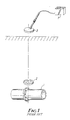
- FIG. 1 An example of arrangement of a conventional detection system using a marker for locating a buried object is shown in Figure 1.
- a detectable marker 2 is installed in proximity to a buried object 1.
- the buried object 1 is a metal tubular member, and the marker 2 is placed under the ground about 10 cm distant upward of the buried object 1.
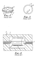
- the marker 2, as shown in greater detail in Figures 2-4, comprises an antenna 6 of the passive resonance type which includes a coil 5 and a capacitor 4 sealed in a marker case 3 which is usually made of polyethylene or the like.
- the object of the present invention is to provide a marker for positioning in proximity to a buried object the marker being detectable to locate the buried object wherein the marker is responsive to an electromagnetic wave enabling the marker to be located and cannot so respond if the marker buried underground is inclined or displaced.
- the marker for locating a buried object is installed in proximity to an underground buried object, and can be detected by use of the fact that an antenna of the passive resonance type is resonantly responsive to an electromagnetic wave of a specific frequency sent from above the ground surface wherein the marker has an antenna of the passive resonance type and includes means for automatically preventing any resonant response to an electromagnetic wave due to changes, such as inclination or displacement, of the marker that may occur subsequent to the initial positioning of the marker.
- the antenna of the passive resonance type housed in the marker is provided with a mercury switch or the like or a part of a coil is extended which can be fixedly secured to a buried object, so that in the case the marker is inclined or displaced, after it has been positioned, the antenna of the passive resonance type is made inoperative, whereby a resonant response of the marker to the electromagnetic wave cannot be produced, thus preventing wasteful labor of excavation by error or the damage of other buried objects due to excavation at a point indicated by the detection of an inclined or displaced marker if the marker were operative.
- the basic configuration of the marker for detecting a buried object according to the present invention is identical to that of the prior art marker that has been described with references to Figures 1-4.
- Those component elements described below which are identical to those component elements shown in Figures 1-4 are designated by the same reference numerals used in Figures 1-4.
- FIG. 5 of the drawings one embodiment of the invention is shown.
- a part of an antenna of the passive resonance type with the essential parts of a marker case is shown in enlarged view.
- the case 3 of the marker 2 is made of a general purpose plastic with a small space formed in part of the interior of the marker case 3, and a hole 12 provided along the entire peripheral annular part of the marker case 3.
- the small space 11 communicates with the hole 12.
- the hole 12 has arranged therein a coil 5 including a multiplicity of windings 5a.
- a capacitor 4 and a mercury switch 13 are housed in the small space 11, and are arranged in a predetermined position.
- the mercury switch 13 is held by three holders 14.
- the capacitor 4 and the mercury switch 13 each have two external terminals.
- a terminal 5b of the coil 5 is connected to a terminal 4a of the capacitor 4 with the other terminal 5c of the coil 5 connected to a terminal 13b of the mercury switch 13.
- the other terminal 4b of the capacitor 4 is connected to the other terminal 13c of the mercury switch 13.
- Figure 5 shows an antenna of the passive resonance type formed with the coil 5, capacitor 4 and the mercury switch 13 connected in series.
- the mercury switch 13 is so constructed as to contain a predetermined amount of fluid mercury 13a in a case. When the mercury switch 13 is in normal position, the mercury 13a provides a conductive path between the two terminals 13b and 13c. When the mercury switch 13 is not in normal position, the mercury 13a moves to remove the conductive path it otherwise provides between the terminals 13b and 13c to cause the switch 13 to present an electrical open.
- the mercury switch 13 is mounted on the marker case 3 in such a way that when the marker 2 is held in horizontal position, the switch 13 is in the state of the normal position wherein a conductive path is provided by the mercury 13a between the terminals 13b and 13c.
- the mercury switch 13 is electrically closed causing marker 2 to be resonantly responsive to a detection electromagnetic wave to enable it to be detected.
- the coil 5 is disconnected from the capacitor 4, so the marker 2 cannot resonantly respond to a detection electromagnetic wave sent from above the ground surface.
- the mercury switch 13 presents an electrical open, with the result that antenna of the passive resonance type ceases to function.
- the marker cannot be detected from the ground surface when the mercury switch 13 presents an electrical open.
- the marker 2 when so inclined will not be detected thereby avoiding the situation where a detection of the marker would erroneously indicate the position of the buried object associated with the marker.
- an operative marker 2 is readily responsive to electromagnetic waves J and K that are perpendicular to the plane thereof. From this showing it is apparent that the accuracy of the marker 2 for establishing the position of a buried object is particularly affected when the marker is moved to an inclined position by movement about the axis 9 of a buried object 1 that is made of a long tubular material such as a water pipe. In this case, the responding point B obtained by the probe 8 present on the ground 15 is greatly displaced from the point A which would otherwise be obtained as a point of burial of the buried object 1 if the marker 2 were not inclined.
- the mercury switch 13 on the marker 2 in such a manner that the mercury switch 13 presents an open when an inclination of the marker 2 occurs due to movement of the marker 2 around the axis 9 of the buried object 1.
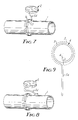
- FIG. 7 shows a second embodiment of the invention.
- a lead wire 5d making up an extension of a part of the coil 5 configuring the antenna of the passive resonance type is led out of the marker 2, and a portion of the lead wire 5d is fixedly attached to the buried object 1 in any suitable manner.
- this fixing is effected by using a bolt 17 of a flange 16 making up a coupling of the buried object 1.
- displacement of the marker 2 relative to the buried object 1 will cause the lead wire 5d to be severed so the antenna of the passive resonance type in the marker cannot respond to an electromagnetic wave sent from the ground surface, thus preventing the marker 2 from being detected.
- the lead wire 5d is to be severed during an ordinary excavation work or the like, it is desirable to use a lead wire which is severed by a tensile strength of about 10 kg.
- Figure 9 shows the electrical component configuration of the antenna of the passive resonance type contained in the marker used for the embodiments shown in Figures 7 and 8. It includes a capacitor 4, a wire coil 5 having a multiplicity of turns, and a lead wire portion 5d extending from the coil 5.
- the wire portion 5d is a part of the windings of the coil 5.
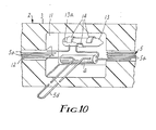
- Figure 10 shows still another embodiment comprising a combination of the first embodiment shown in Figure 5 and the second embodiment showing in Figures 7-9.
- a marker is provided which comprises a mercury switch 13 adapted to be on or off according to the position of the marker 2 and a lead wire 5d made of an outward extension of a part of the coil 5.
- the marker 2 can become inoperative due to the marker becoming inclined relative to the horizontal or being displaced relative to the buried object with which it is used.
- EMS electronic marker system
- the marker case 3 used in each of the above-mentioned embodiments may be made using general-purpose plastic such as polyethylene.
- the coil 5 for the antenna 6 of the passive resonant type requires about 10 to 15 meters of wire to provide 15 to 23 turns.
- the wire core is about 0.5 mm in diameter and is 5 to 15 kg in tensile strength.
- the capacitor 4 is 0.008 to 0.015 ⁇ F.
- the resonant frequency for a marker is 80 to 160 KHz, and the detection distance thereof is normally several tens to 140 cm.
- the mercury switch 13, as shown in the first embodiment can be a Model B mercury switch available from Nemoto Limited in Japan.
- the lead wire 5d portion used in the second embodiment is about 3 to 6 cm long.
- a ferrite marker is also available.
- This marker which includes a winding or coil wound on a ferrite core, operates on the same basic principle.
- the mercury switch and an antenna of passive resonance type aspects used in the above-mentioned embodiments may be applied also to this marker.
Landscapes
- Engineering & Computer Science (AREA)
- General Engineering & Computer Science (AREA)
- Physics & Mathematics (AREA)
- Life Sciences & Earth Sciences (AREA)
- General Life Sciences & Earth Sciences (AREA)
- General Physics & Mathematics (AREA)
- Geophysics (AREA)
- Mechanical Engineering (AREA)
- Radar Systems Or Details Thereof (AREA)
- Geophysics And Detection Of Objects (AREA)
Applications Claiming Priority (2)
| Application Number | Priority Date | Filing Date | Title |
|---|---|---|---|
| JP1986176955U JPH0449596Y2 (de) | 1986-11-18 | 1986-11-18 | |
| JP176955/86U | 1986-11-18 |
Publications (2)
| Publication Number | Publication Date |
|---|---|
| EP0268420A2 true EP0268420A2 (de) | 1988-05-25 |
| EP0268420A3 EP0268420A3 (de) | 1989-01-18 |
Family
ID=16022642
Family Applications (1)
| Application Number | Title | Priority Date | Filing Date |
|---|---|---|---|
| EP87309969A Withdrawn EP0268420A3 (de) | 1986-11-18 | 1987-11-11 | Markierer zur Detektion eines vergrabenen Objektes |
Country Status (4)
| Country | Link |
|---|---|
| US (1) | US4873533A (de) |
| EP (1) | EP0268420A3 (de) |
| JP (1) | JPH0449596Y2 (de) |
| DK (1) | DK601487A (de) |
Cited By (2)
| Publication number | Priority date | Publication date | Assignee | Title |
|---|---|---|---|---|
| EP0408320A3 (en) * | 1989-07-11 | 1992-05-13 | Du Pont (Uk) Limited | Identification of hidden pipes etc |
| EP0553245B1 (de) * | 1990-10-15 | 1994-12-14 | Plymouth Francaise | Detektierbare anordnung zur identifikation von optisch unsichtbaren objekten |
Families Citing this family (35)
| Publication number | Priority date | Publication date | Assignee | Title |
|---|---|---|---|---|
| FR2685519A1 (fr) * | 1991-12-20 | 1993-06-25 | Gemplus Card Int | Systeme pour l'identification de recipients et notamment de bouteilles de gaz. |
| JPH10152030A (ja) * | 1996-11-22 | 1998-06-09 | Mitsubishi Heavy Ind Ltd | 移動体自動制御システム |
| US6388575B1 (en) * | 1999-11-05 | 2002-05-14 | Industrial Technology, Inc. | Addressable underground marker |
| US6621417B2 (en) * | 2001-08-09 | 2003-09-16 | Edgar Alan Duncan | Passive RFID transponder/reader system and method for hidden obstacle detection and avoidance |
| US6812707B2 (en) | 2001-11-27 | 2004-11-02 | Mitsubishi Materials Corporation | Detection element for objects and detection device using the same |
| US6690278B2 (en) | 2001-12-28 | 2004-02-10 | Gas Technology Institute | Electronic marker for metallic valve box covers |
| US7391324B1 (en) | 2005-11-14 | 2008-06-24 | Gpk Products, Inc. | Locator plug system |
| US8473209B2 (en) | 2007-03-13 | 2013-06-25 | Certusview Technologies, Llc | Marking apparatus and marking methods using marking dispenser with machine-readable ID mechanism |
| US8060304B2 (en) | 2007-04-04 | 2011-11-15 | Certusview Technologies, Llc | Marking system and method |
| US8700325B2 (en) | 2007-03-13 | 2014-04-15 | Certusview Technologies, Llc | Marking apparatus and methods for creating an electronic record of marking operations |
| US7640105B2 (en) | 2007-03-13 | 2009-12-29 | Certus View Technologies, LLC | Marking system and method with location and/or time tracking |
| BRPI0701614A2 (pt) * | 2007-04-13 | 2011-08-30 | Forno Alexandre De Oliveira Dal | dispositivo, método de instalação do mesmo, sistema e método de localização e identificação e método para mapeamento e execução de plantas situacionais de dutos, cabos ou objetos enterrados ou escondidos sem necessidade de obra invasiva e/ou destrutiva |
| US7915894B2 (en) * | 2007-08-30 | 2011-03-29 | Minarovic Joe T | Service tee marker fixture with concentric attachment sleeve |
| US7696879B2 (en) * | 2007-12-18 | 2010-04-13 | Alcatel Lucent | Ascertaining physical routing of cabling interconnects |
| US8280631B2 (en) | 2008-10-02 | 2012-10-02 | Certusview Technologies, Llc | Methods and apparatus for generating an electronic record of a marking operation based on marking device actuations |
| US8965700B2 (en) | 2008-10-02 | 2015-02-24 | Certusview Technologies, Llc | Methods and apparatus for generating an electronic record of environmental landmarks based on marking device actuations |
| US8424486B2 (en) | 2008-07-10 | 2013-04-23 | Certusview Technologies, Llc | Marker detection mechanisms for use in marking devices and methods of using same |
| US8749239B2 (en) | 2008-10-02 | 2014-06-10 | Certusview Technologies, Llc | Locate apparatus having enhanced features for underground facility locate operations, and associated methods and systems |
| US20100188088A1 (en) * | 2008-10-02 | 2010-07-29 | Certusview Technologies, Llc | Methods and apparatus for displaying and processing facilities map information and/or other image information on a locate device |
| US20100198663A1 (en) * | 2008-10-02 | 2010-08-05 | Certusview Technologies, Llc | Methods and apparatus for overlaying electronic marking information on facilities map information and/or other image information displayed on a marking device |
| US20100188407A1 (en) * | 2008-10-02 | 2010-07-29 | Certusview Technologies, Llc | Methods and apparatus for displaying and processing facilities map information and/or other image information on a marking device |
| US8442766B2 (en) | 2008-10-02 | 2013-05-14 | Certusview Technologies, Llc | Marking apparatus having enhanced features for underground facility marking operations, and associated methods and systems |
| GB2497028B (en) | 2008-10-02 | 2013-07-03 | Certusview Technologies Llc | Methods and apparatus for generating electronic records of locate operations |
| CA2691780C (en) | 2009-02-11 | 2015-09-22 | Certusview Technologies, Llc | Management system, and associated methods and apparatus, for providing automatic assesment of a locate operation |
| CA2771286C (en) | 2009-08-11 | 2016-08-30 | Certusview Technologies, Llc | Locating equipment communicatively coupled to or equipped with a mobile/portable device |
| CA2710189C (en) | 2009-08-20 | 2012-05-08 | Certusview Technologies, Llc | Methods and apparatus for assessing marking operations based on acceleration information |
| CA2713282C (en) | 2009-08-20 | 2013-03-19 | Certusview Technologies, Llc | Marking device with transmitter for triangulating location during marking operations |
| WO2011022102A1 (en) | 2009-08-20 | 2011-02-24 | Certusview Technologies, Llc | Methods and marking devices with mechanisms for indicating and/or detecting marking material color |
| USD634656S1 (en) | 2010-03-01 | 2011-03-22 | Certusview Technologies, Llc | Shaft of a marking device |
| USD634657S1 (en) | 2010-03-01 | 2011-03-22 | Certusview Technologies, Llc | Paint holder of a marking device |
| USD634655S1 (en) | 2010-03-01 | 2011-03-22 | Certusview Technologies, Llc | Handle of a marking device |
| USD643321S1 (en) | 2010-03-01 | 2011-08-16 | Certusview Technologies, Llc | Marking device |
| US20120325359A1 (en) * | 2011-06-27 | 2012-12-27 | 3M Innovative Properties Company | Flexible magnetic core electronic marker |
| USD684067S1 (en) | 2012-02-15 | 2013-06-11 | Certusview Technologies, Llc | Modular marking device |
| WO2017143090A1 (en) * | 2016-02-16 | 2017-08-24 | SeeScan, Inc. | Buried utility marker devices and systems |
Family Cites Families (10)
| Publication number | Priority date | Publication date | Assignee | Title |
|---|---|---|---|---|
| US3216016A (en) * | 1962-08-09 | 1965-11-02 | Control Data Corp | Buried inner and outer loop conductors forming annulus producing radiation in plane of annulus |
| US3836842A (en) * | 1973-01-22 | 1974-09-17 | Bell Canada Northern Electric | Encapsulated electrically resonant circuit and interrogating apparatus and method for finding same in various locations |
| US3978321A (en) * | 1974-08-22 | 1976-08-31 | Doggett Robert E | Portable hand-carried automobile counting device |
| US4119908A (en) * | 1975-11-28 | 1978-10-10 | A. P. C. Industries, Inc. | Method for locating buried markers which are disposed along the path of an underground conductor |
| US4163127A (en) * | 1978-01-11 | 1979-07-31 | J. H. Electric Co., Inc. | Position sensitive safety switch |
| US4334227A (en) * | 1980-09-26 | 1982-06-08 | A.P.C. Industries, Inc. | Electronic marker device and method of making same |
| GB2131655A (en) * | 1982-12-09 | 1984-06-20 | Locat Developments Ltd | Radio rescue beacon |
| US4618861A (en) * | 1985-03-20 | 1986-10-21 | Cornell Research Foundation, Inc. | Passive activity monitor for livestock |
| US4712094A (en) * | 1986-05-29 | 1987-12-08 | Minnesota Mining And Manufacturing Company | Self-orienting passive marker structure |
| US4755806A (en) * | 1987-03-09 | 1988-07-05 | Villarreal Juan M | Movement sensor |
-
1986
- 1986-11-18 JP JP1986176955U patent/JPH0449596Y2/ja not_active Expired
-
1987
- 1987-10-09 US US07/106,343 patent/US4873533A/en not_active Expired - Fee Related
- 1987-11-11 EP EP87309969A patent/EP0268420A3/de not_active Withdrawn
- 1987-11-16 DK DK601487A patent/DK601487A/da not_active Application Discontinuation
Cited By (2)
| Publication number | Priority date | Publication date | Assignee | Title |
|---|---|---|---|---|
| EP0408320A3 (en) * | 1989-07-11 | 1992-05-13 | Du Pont (Uk) Limited | Identification of hidden pipes etc |
| EP0553245B1 (de) * | 1990-10-15 | 1994-12-14 | Plymouth Francaise | Detektierbare anordnung zur identifikation von optisch unsichtbaren objekten |
Also Published As
| Publication number | Publication date |
|---|---|
| EP0268420A3 (de) | 1989-01-18 |
| JPS6381277U (de) | 1988-05-28 |
| DK601487A (da) | 1988-05-19 |
| US4873533A (en) | 1989-10-10 |
| DK601487D0 (da) | 1987-11-16 |
| JPH0449596Y2 (de) | 1992-11-20 |
Similar Documents
| Publication | Publication Date | Title |
|---|---|---|
| US4873533A (en) | Marker for locating a buried object | |
| US4119908A (en) | Method for locating buried markers which are disposed along the path of an underground conductor | |
| EP0247854B1 (de) | Struktur einer passiven Marke | |
| US6812707B2 (en) | Detection element for objects and detection device using the same | |
| EP0182488B1 (de) | Fernmessung von Zuständen | |
| US4767237A (en) | Marking tape with wire conductors and methods for use | |
| US5699048A (en) | Omnidirectional passive electrical marker for underground use | |
| US4947012A (en) | Electrofusion marker | |
| WO2001027658A2 (en) | Buried closure guard with electronic marker | |
| JP3319506B2 (ja) | 金属体用rfid素子及びこれを用いた金属体の識別装置 | |
| US6049279A (en) | Detectable transponder conduit end cap | |
| JP2001099946A (ja) | 物体の埋設位置検出方法及びその装置 | |
| CA1204486A (en) | Marker for subterranean marking and a novel application for such a marker | |
| AU600200B2 (en) | System and method with passive resonant circuit markers for locating buried electrical conductors | |
| EP1152262A1 (de) | Objektdetektionselement und anwendung desselben. | |
| KR20150061255A (ko) | 지하매설관 특정위치 탐지시스템 및 방법 | |
| US4233523A (en) | Pressure sensitive device | |
| AU600008B2 (en) | Marking tape with wire conductors and methods for use | |
| US7692594B2 (en) | Pop-up cable electronic marker | |
| JPH07317107A (ja) | 掘削における地中埋設物の損傷防止方法 | |
| US6690278B2 (en) | Electronic marker for metallic valve box covers | |
| CA2251443A1 (en) | Faulty filter detection technique | |
| EP1695119B1 (de) | Bandmarkierung mit passiven resonanzkreisen und verwendungsverfahren | |
| KR100614204B1 (ko) | 케이블의 위치탐지장치 및 위치검출방법 | |
| AU2019440229B2 (en) | Disconnector device with passive radio device, grid protection system having the disconnector device, and method for indicating a state of the disconnector device |
Legal Events
| Date | Code | Title | Description |
|---|---|---|---|
| PUAI | Public reference made under article 153(3) epc to a published international application that has entered the european phase |
Free format text: ORIGINAL CODE: 0009012 |
|
| AK | Designated contracting states |
Kind code of ref document: A2 Designated state(s): DE FR GB |
|
| PUAL | Search report despatched |
Free format text: ORIGINAL CODE: 0009013 |
|
| AK | Designated contracting states |
Kind code of ref document: A3 Designated state(s): DE FR GB |
|
| 17P | Request for examination filed |
Effective date: 19890713 |
|
| STAA | Information on the status of an ep patent application or granted ep patent |
Free format text: STATUS: THE APPLICATION HAS BEEN WITHDRAWN |
|
| 18W | Application withdrawn |
Withdrawal date: 19901030 |
|
| R18W | Application withdrawn (corrected) |
Effective date: 19901030 |
|
| RIN1 | Information on inventor provided before grant (corrected) |
Inventor name: OIKE, TOMOYASUC/O MINNESOTA MINING AND |