EP0268469A1 - Procédé pour la synthèse d'ammoniac - Google Patents
Procédé pour la synthèse d'ammoniac Download PDFInfo
- Publication number
- EP0268469A1 EP0268469A1 EP87310182A EP87310182A EP0268469A1 EP 0268469 A1 EP0268469 A1 EP 0268469A1 EP 87310182 A EP87310182 A EP 87310182A EP 87310182 A EP87310182 A EP 87310182A EP 0268469 A1 EP0268469 A1 EP 0268469A1
- Authority
- EP
- European Patent Office
- Prior art keywords
- recited
- effluent
- catalyst
- catalyst beds
- cooled
- Prior art date
- Legal status (The legal status is an assumption and is not a legal conclusion. Google has not performed a legal analysis and makes no representation as to the accuracy of the status listed.)
- Granted
Links
Images

Classifications
-
- C—CHEMISTRY; METALLURGY
- C01—INORGANIC CHEMISTRY
- C01C—AMMONIA; CYANOGEN; COMPOUNDS THEREOF
- C01C1/00—Ammonia; Compounds thereof
- C01C1/02—Preparation, purification or separation of ammonia
- C01C1/04—Preparation of ammonia by synthesis
- C01C1/0405—Preparation of ammonia by synthesis from N2 and H2 in presence of a catalyst
-
- Y—GENERAL TAGGING OF NEW TECHNOLOGICAL DEVELOPMENTS; GENERAL TAGGING OF CROSS-SECTIONAL TECHNOLOGIES SPANNING OVER SEVERAL SECTIONS OF THE IPC; TECHNICAL SUBJECTS COVERED BY FORMER USPC CROSS-REFERENCE ART COLLECTIONS [XRACs] AND DIGESTS
- Y02—TECHNOLOGIES OR APPLICATIONS FOR MITIGATION OR ADAPTATION AGAINST CLIMATE CHANGE
- Y02P—CLIMATE CHANGE MITIGATION TECHNOLOGIES IN THE PRODUCTION OR PROCESSING OF GOODS
- Y02P20/00—Technologies relating to chemical industry
- Y02P20/50—Improvements relating to the production of bulk chemicals
- Y02P20/52—Improvements relating to the production of bulk chemicals using catalysts, e.g. selective catalysts
Definitions
- This invention relates to the synthesis of ammonia. More particularly, this invention relates to a novel continuous process for producing ammonia which provides a more efficient and less costly means of controlling the temperature at which the synthesis reaction is carried out. This in turn provides more efficient heat recovery, using less heat exchanger surface area, and higher conversions of synthesis gas to ammonia than hitherto-practiced ammonia synthesis processes.
- Ammonia is produced commercially today by continuous processes which involve the seemingly straightforward reaction between stoichiometric amounts of nitrogen and hydrogen: N2 + 3H2---- ⁇ 2NH3.
- a gaseous mixture containing nitrogen and hydrogen is passed sequentially over two or more catalyst beds containing, for example, finely divided iron or promoted iron catalyst, at relatively high pressure and controlled temperature.
- a typical prior art process for synthesizing ammonia -- for example that disclosed in Wright et al U.S. Patent No. 3,851,046 or in Grotz U.S. Patent No. 4,510,123 -- involves:
- the temperature of the gas emerging from the first and any subsequent catalyst beds is sufficiently high to be thermodynamically inhibitory to further ammonia-forming reaction. Therefore, the effluent from one catalyst bed must be cooled if it is to be passed through another catalyst bed to increase the percentage conversion of the synthesis gas to ammonia. Temperature regulation is thus of prime importance to the efficiency of multiple catalyst bed ammonia synthesis processes.
- FIG. 1 Appar atus in which the Wright et al patent's process can be carried out is illustrated schematically in FIG. 1 attached hereto; bypass valves 102 and 104 in FIG.1 are not specifically disclosed in the Wright et al patent, but have been included for reasons discussed hereinbelow.
- fresh syngas introduced through a conduit 106 is passed through a conduit 108 to a heat exchanger 110 and heated therein to a temperature of 280°C.
- the thus-heated syngas is then passed through a conduit 112 to a second heat exchanger 114 and heated therein to a temperature of 400°C.
- the high temperature syngas is then passed through a conduit 116 to a catalytic converter 118 in which the exothermic ammonia-forming reaction causes the temperature to rise to about 520°C.
- the partially converted gas exiting the catalytic converter 118 through a conduit 120 is then cooled in the second heat exchanger 114 to a temperature of about 400°C, then passed through a conduit 122 to a second catalytic converter 124, where again the conversion of hydrogen and nitrogen to ammonia results in a temperature rise in the stream, this time to about 480°C.
- Effluent from the second catalytic converter 124 passes through a conduit 126 to a steam generator or superheater 128, and is cooled to about 320°C by generating high pressure steam in the steam generator 128.
- the thus-cooled stream is then passed through a conduit 130 and further cooled by heat exchange with fresh syngas in the first heat exchanger 110.
- Temperature regulation in such a process could be accomplished by use of the added bypass valves 102 and 104.
- the bypass valve 104 is opened to cause a lower temperature in the conduit 116, the conversion in the first catalytic converter 118 would increase, causing an increased effluent temperature in the gas exiting the first catalytic converter through the conduit 120. Since opening the bypass valve 104 would also result in less cooling of the effluent from the first catalytic converter 118 in the second heat exchanger 114, the temperature of the gas entering the second catalytic converter 124 through the conduit 122 would increase, resulting in a decrease in conversion in the second catalyst bed. Thus, the overall conversion achieved in the first and the second catalyst beds would remain the same as it was before the valve 104 was opened.
- a bypass valve 102 would have to be used. Opening the bypass valve 102 would decrease catalytic converter inlet temperatures, resulting in higher conversions. Higher conversions in turn would permit a lower synthesis pressure, resulting in savings in steam consumption in the turbine that drives the synthesis gas compressor or any other compressor in the plant. These savings would be offset, however, by the loss of steam production from the steam generator as a result of the lower temperature of the gas exiting the catalytic converter 124. Thus, opening the bypass valve 102 would have the disadvantage of reducing overall heat recovery.
- U.S. Patent No. 4,510,123 discloses a three or more catalyst bed ammonia synthesis system in which the temperature of the first bed is regulated by heat exchange between the effluent of the first bed and fresh syngas and the temperatures of subsequent beds are regulated by high pressure steam generation.
- the use of additional catalyst beds permits higher conversions to ammonia.
- the first two beds of this three or more bed system are subject to the same temperature control limitations as described above for the process of the Wright et al patent.
- U.S. Patent No. 4,230,680 describe a three bed process for producing ammonia from syngas in which temperature is controlled by passing a portion of the effluent from each of the three catalyst beds through heat exchangers to which all or a portion of the fresh syngas is also fed to provide a heat sink. Effluent from the third bed is cooled by "various plant fluid(s)", "such as boiler feed water”. If boiler feed water or other such cooling fluid is used, higher ammonia conversions in the first two beds can be achieved than are achievable in the processes previously discussed. But since no high pressure steam is generated, much less heat recovery is achieved. And, if effluent heat is used to generate steam instead of to heat boiler feed water, ammonia conversions are limited as in the previously discussed processes.
- U.S. Patent No. 4,215,099 to Pinto et al discloses a process for producing ammonia or methanol in which the synthesis gas fed to the first catalyst bed is in heat exchange with a coolant, preferably feed synthesis gas, and the second catalyst bed is adiabatic. This system is said to give a higher conversion to ammonia in the first catalyst bed, but does so with reduced heat recovery.
- U.S. Patent No. 4,213,954 discloses an ammonia synthesis in which steam is superheated in the synthesis section of the process to better control steam rates in the event of shutdown of the synthesis section, i.e., to avoid overheating steam superheaters in the synthesis gas generating section of the process.
- This process is operated at a synthesis pressure under 150, and preferably 40 - 80, bar abs, positions the steam superheater so that it will cool reacted gas before this gas is cooled by any other heat exchange, and achieves 15-30% or more of the total plant steam superheating.
- a continuous ammonia synthesis in which a synthesis gas mixture containing nitrogen and hydrogen is passed sequentially over two or more catalyst beds containing ammonia synthesis catalyst at relatively high pressure and controlled temperature -- the temperature of the gaseous effluent from the first catalyst bed is regulated, i.e., lowered, before this effluent enters the next such catalyst bed, by passing this effluent through a high temperature heat sink to effect cooling by heat exchange in the high temperature heat sink.
- the gaseous effluent from the first catalyst bed Prior to being cooled in the high temperature heat sink, the gaseous effluent from the first catalyst bed can undergo a partial reduction in temperature by being subjected to heat exchange with the synthesis gas mixture being fed to the first catalyst bed.
- the temperature of the gaseous effluents from the second and subsequent catalyst beds can likewise be lowered to whatever extent necessary to provide optimum c onversion of nitrogen and hydrogen to ammonia before such effluents enter succeeding catalyst beds in any convenient manner, e.g., by heat exchange in a high pressure steam generator.
- the process of the present invention uses a high temperature heat sink: -preferably positioned to effect heat exchange after the partially reacted synthesis gas has been subjected to an initial heat exchange, -primarily to regulate the temperature of the partially reacted synthesis gas, and control the temperature of this gas entering the second catalytic converter to a desired level, -to effect less than 15 percent of the total plant steam superheating, -in an ammonia synthesis process which is preferably carried out at a pressure of greater than 100 bar abs.
- Another object of this invention is to provide a novel continuous process for synthesizing ammonia in which the manner in which the ammonia synthesis reaction temperature is controlled provides more efficient heat recovery, using less heat exchanger surface area, and higher conversions of synthesis gas to ammonia than hitherto-practiced ammonia synthesis processes.
- the terms “syngas” and “synthesis gas” refer to a mixture of nitrogen and hydrogen, preferably in an approximate molar ratio of 1:3, respectively, which may also contain inert diluents such as argon, helium, methane or the like. While it is desirable to have zero diluent concentration, this is seldom achieved, and the syngas feed, although preferably composed substantially of hydrogen and nitrogen in an approximately stoichiometric ratio, may contain the same amounts of inert diluent(s) as prior art ammonia processes, inasmuch as the process of this invention is affected by the presence of inert diluents in essentially the same manner as are such prior art processes. Further, the approximate stoichiometric ratio of nitrogen to hydrogen in the gaseous feed to the process of this invention can range from about 1:2 or less to about 1:4 or higher without substantial detriment to the yields of ammonia achievable.
- final product effluent refers to a gas stream which has passed through the entire reaction, i.e., through however many catalyst beds are employed, and which is to be subjected to known recovery processes to extract the ammonia therefrom.
- Catalysts which can be used to accelerate the synthesis of ammonia are well known in the art. Included among such catalysts are finely divided iron and promoted iron catalysts. Presumably the discovery of a superior catalyst which would accelerate the reaction sufficiently so that it would proceed at an acceptable rate at, fo r example, a temperature of from about 300°C to about 360°C, would alter the preferred reaction temperatures recited hereinbelow at which the process of the present invention will be practiced. The general principle on which the process of the present invention rests would not, however, be altered by the substitution of such improved catalysts, should they become known. Of course, the preferred temperature ranges would be correspondingly lowered if such better catalysts were used.
- the syngas feed to the first catalyst bed and the effluents from this first and subsequent catalyst beds which will be fed to succeeding catalyst beds in a sequence of catalytic reactors should be at a temperature of not more than about 430°C, and preferably at a temperature within the range of from about 370°C to about 420°C.
- a variety of designs for apparatus in which the process of the present invention can be carried out are, in general, also well known in the art.
- Two major known types of catalytic converters for ammonia synthesis are radial flow converters and axial flow converters. In the former, the synthesis gas flows radially through the catalyst bed. In the latter, the synthesis gas flows downwardly or axially through the catalyst bed.
- the pattern of gas flow through the catalytic converter is not critical to the process of this invention.
- Adiabatic catalytic converters are disclosed as being useful in the process of this invention.
- the first catalytic converter used in the process could also be a quench type converter followed by a feed effluent heat exchanger and a steam superheater or high temperature heat sink which uses an outside heat removal medium other than synthetic gas.
- the first catalyst pass results in a conversion of from about 15 to 20% of the starting materials to ammonia, with succeeding passes resulting in further conversions.
- the final product effluent should contain approximately 20% ammonia by volume, which represents an approximately 30-35% conversion of the nitrogen starting material.
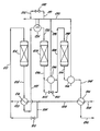
- syngas enters the system from a source (not shown) through a conduit 202 and is passed through a first heat exchanger 204 in which the heat source is the final product effluent which enters the heat exchanger 204 through a conduit 248.
- the effluent from the heat exchanger 216 is combined at a conduit 220 with the syngas from the bypass control line 208 which has passed through the valve 210, and the mixture is fed through the conduit 212 to the first catalytic converter 214.
- the temperature of the combined gasses as they enter the first catalytic converter 214 is, as indicated above, preferably between about 370°C and about 420°C.
- a portion of the nitrogen and hydrogen is converted to ammonia in an exothermic reaction such that the temperature of the gas exiting the first catalytic converter 214 through a conduit 218 is between about 480°C and about 540°C.
- the effluent is cooled in the heat exchanger 216 by heat exchange with the feed syngas so that the temperature of the effluent exiting the heat exchanger 216 through a conduit 222 is preferably between about 390°C and about 440 °C.
- the conduit 222 carries the effluent exiting the heat exchanger 216 to a high temperature heat sink which, in this example, is a steam superheater 224, where this effluent is further cooled to a desired level by providing heat to at least a portion of the steam which has been generated in secondary high temperature heat sinks which, in this example, are the high pressure steam generators 234 and 246.
- Control of the gas temperature in a conduit 226, before the feed gas enters a second catalytic converter 228, is maintained by a bypass line 231, controlled by a valve 232 which controls the amount of fluid or cooling steam passing through the conduits 233 and from the high pressure steam generator 234.
- the gas entering the second catalytic converter 228 is preferably at a temperature between about 370°C and 420°C. Further conversion to ammonia takes place in the second catalytic converter 228, with generation of sufficient heat to provide an effluent with an exit temperature of from about 450°C to about 510°C.
- This effluent gas exiting the second catalytic converter 228 through a conduit 236 is cooled in the high pressure steam generator 234 to a temperature of from about 370°C to about 420°C, the preferred temperature for the pass over the catalyst bed in a third catalytic converter 238. Control over this process variable is maintained by a control valve 240 in a bypass line 242, the fraction of gas bypassing the high pressure steam generator 234 being sufficient to retain the proper high temperature.
- reaction taking place in the third catalytic converter 238 involving feed gas passed through a conduit 246 to this converter results in an increase in temperature of the flowing gas mixture so that the temperature of the gas entering the high pressure steam generator 246 through a conduit 244 is from about 420°C to about 480°C.
- the gas In the high pressure steam generator 246, the gas is cooled to a temperature of from about 300°C to about 400°C.
- the gas emerging from the high pressure steam generator 246 is passed through a conduit 248 to the heat exchanger 204 to heat the original feed syngas to a temperature of from about 250°C to about 320°C.
- the final product effluent which exits the heat exchanger 204 through a conduit 250 is then subjected to a conventional ammonia recovery process.
- the high pressure steam generated in high pressure steam generators 234 and 246 is combined in the conduit 230.
- the combined flowing steam is then divided so that a portion of it is heated in the steam superheater 224 to a temperature of from about 320°C to about 400°C, while the other portion of the high pressure steam passes through the valve 232 and the conduit 252 to other parts of the plant.
- the preferred embodiment also uses steam generated in the high pressure steam generators 234 and 246 to cool the feed to the second catalytic converter 228 in the steam superheater 224.
- the invention is not limited to using steam generated in the ammonia synthesis portion of the ammonia plant in the steam superheater 224; steam generated anywhere the plant may also be used.
- a high temperature heat sink which uses other outside heat removal mediums, such as boiler feed water, steam generation, feed gas or process steam or other mediums other than synthesis gas could also be used.
- a continuous feed gas stream made up of: is introduced at 155 bar pressure and a temperature of 51°C through the conduit 202.
- the temperature of the gas stream after it passes through the heat exchanger 204 is 281°C.
- the temperature of the gas stream after passing through the heat exchanger 234 and being recombined with the portion of the gas stream recirculated through the bypass valve 210 is 393°C. 1 / Argon and helium flow remain substantially constant.
- the gas stream is then passed to a first catalytic converter 214, where partial conversion of its nitrogen and hydrogen content to ammonia occurs.
- This first catalytic converter is a cylindrical vessel whose inside diameter is 3 meters and whose length is 3.44 meters, containing approximately 22 cubic meters of iron oxide ammonia synthesis catalyst.
- the gas stream exiting the first catalytic converter is at a temperature of 516°C and has the following composition, exclusive of argon and helium: This represents a conversion at this point of approximately 15% of the amount of nitrogen in the initial feed gas stream to ammonia.
- the gas stream exiting the first catalytic converter is passed through a heat exchanger 216 where it attains a temperature of 403°C, and then through a steam superheater 224 to decrease its temperature, upon exiting the superheater, to 380°C.
- the partially converted gas stream is then passed to a second catalytic converter 228, a cylindrical vessel whose inside diameter is 3.35 meters and whose length is 7.72 meters, containing approximately 58 cubic meters of iron oxide ammonia synthesis catalyst.
- the gas stream exiting the second catalytic converter is at a temperature of 467°C and has the following composition, again exclusive of argon and helium: This represents a conversion at this point of approximately 25% of the amount of nitrogen in the initial feed gas stream to ammonia.
- a portion of the gas stream exiting the second catalytic converter is passed through a high pressure steam generator 234.
- the effluent from this high pressure steam generator when combined with the other portion of the gas stream exiting the second catalytic converter which is circulated through a bypass valve 240, is at a temperature of 380°C when it enters a third catalytic converter 238.
- This third catalytic converter a cylindrical vessel whose inside diameter is 3.35 meters and whose length is 7.72 meters, contains 68 cubic meters of iron oxide ammonia synthesis catalyst.
- the gas stream exiting the third catalytic converter is at a temperature of 436°C and has the following composition, again exclusive of argon and helium: This represents a conversion at this point of approximately 32% of the amount of nitrogen in the initial feed gas stream to ammonia.
- the temperature of the gas stream exiting the third catalytic converter is then lowered to 318°C by passing it through a high pressure steam generator 246, and then to 73°C (as it exits through a conduit 250 as final product effluent) by passing it through a heat exchanger 204.
- the final product effluent is then passed to the plant's recovery process section to extract the ammonia therefrom.
Landscapes
- Chemical & Material Sciences (AREA)
- Organic Chemistry (AREA)
- Chemical Kinetics & Catalysis (AREA)
- Analytical Chemistry (AREA)
- Inorganic Chemistry (AREA)
- Organic Low-Molecular-Weight Compounds And Preparation Thereof (AREA)
- Catalysts (AREA)
- Industrial Gases (AREA)
- Physical Or Chemical Processes And Apparatus (AREA)
- Devices And Processes Conducted In The Presence Of Fluids And Solid Particles (AREA)
Applications Claiming Priority (4)
| Application Number | Priority Date | Filing Date | Title |
|---|---|---|---|
| US932614 | 1986-11-20 | ||
| US06/932,614 US4744966A (en) | 1986-11-20 | 1986-11-20 | Process for synthesizing ammonia |
| US119624 | 1987-11-12 | ||
| US07/119,624 US4867959A (en) | 1986-11-20 | 1987-11-12 | Process for synthesizing ammonia |
Publications (2)
| Publication Number | Publication Date |
|---|---|
| EP0268469A1 true EP0268469A1 (fr) | 1988-05-25 |
| EP0268469B1 EP0268469B1 (fr) | 1995-05-10 |
Family
ID=26817520
Family Applications (1)
| Application Number | Title | Priority Date | Filing Date |
|---|---|---|---|
| EP87310182A Expired - Lifetime EP0268469B1 (fr) | 1986-11-20 | 1987-11-18 | Procédé pour la synthèse d'ammoniac |
Country Status (7)
| Country | Link |
|---|---|
| US (1) | US4867959A (fr) |
| EP (1) | EP0268469B1 (fr) |
| JP (1) | JPS63288908A (fr) |
| AT (1) | ATE122323T1 (fr) |
| AU (1) | AU601781B2 (fr) |
| DE (1) | DE3751286T2 (fr) |
| NO (1) | NO874819L (fr) |
Cited By (6)
| Publication number | Priority date | Publication date | Assignee | Title |
|---|---|---|---|---|
| EP0390420A1 (fr) * | 1989-03-22 | 1990-10-03 | C F Braun Inc | Système combiné d'échange de chaleur pour des effluents issus de réacteurs de synthèse d'ammoniac |
| WO1992005112A1 (fr) * | 1990-09-24 | 1992-04-02 | C.F. Braun Inc. | Synthese de l'ammoniac a conversion elevee |
| KR100445253B1 (ko) * | 2000-02-10 | 2004-08-21 | 할도르 토프쉐 에이/에스 | 암모니아 제조를 위한 방법과 반응기 |
| WO2005115607A1 (fr) * | 2004-05-28 | 2005-12-08 | Ammonia Casale S.A. | Procede pour effectuer des reaction en phase gazeuse exothermiques catalytiques heterogenes |
| WO2009156085A3 (fr) * | 2008-06-26 | 2010-08-26 | Haldor Topsøe A/S | Processus de production d'ammoniac |
| DE102022205453A1 (de) | 2022-05-31 | 2023-11-30 | Siemens Energy Global GmbH & Co. KG | Anlage und Verfahren zur Erzeugung von Ammoniak |
Families Citing this family (15)
| Publication number | Priority date | Publication date | Assignee | Title |
|---|---|---|---|---|
| ES2030940T5 (es) * | 1988-06-27 | 1996-03-16 | Ammonia Casale Sa | Proceso y reactor para sintesis heterogenea exotermica con varios lechos cataliticos y con recuperacion externa de calor. |
| US5236671A (en) * | 1990-09-24 | 1993-08-17 | C. F. Braun, Inc. | Apparatus for ammonia synthesis |
| US5427760A (en) * | 1994-02-22 | 1995-06-27 | Brown & Root Petroleum And Chemicals | Axial-radial reactors in the braun ammonia synloop with extrnal heat sink |
| US5840933A (en) * | 1996-10-29 | 1998-11-24 | Arco Chemical Technology, L.P. | Catalytic converter system and progress |
| DK173023B1 (da) * | 1997-04-21 | 1999-11-15 | Topsoe Haldor As | Fremgangsmåde og reaktor til fremstilling af ammoniak |
| PL190772B1 (pl) * | 1998-03-05 | 2006-01-31 | Haldor Topsoe As | Sposób wytwarzania amoniaku oraz konwerter amoniaku |
| DE10116150A1 (de) * | 2001-03-31 | 2002-10-10 | Mg Technologies Ag | Verfahren zum katalytischen Erzeugen von Ammoniak aus Synthesegas |
| GB0113078D0 (en) * | 2001-05-30 | 2001-07-18 | Kvaerner Process Tech Ltd | Process and plant |
| US7435401B2 (en) * | 2004-07-02 | 2008-10-14 | Kellogg Brown & Root Llc | Pseudoisothermal ammonia process |
| US7892511B2 (en) * | 2004-07-02 | 2011-02-22 | Kellogg Brown & Root Llc | Pseudoisothermal ammonia process |
| US20060228284A1 (en) * | 2005-04-11 | 2006-10-12 | Schmidt Craig A | Integration of gasification and ammonia production |
| EP2354092A1 (fr) * | 2010-01-29 | 2011-08-10 | Ammonia Casale S.A. | Procédé de modernisation de la boucle de synthèse d'une installation de fabrication d'ammoniac |
| US10106430B2 (en) | 2013-12-30 | 2018-10-23 | Saudi Arabian Oil Company | Oxycombustion systems and methods with thermally integrated ammonia synthesis |
| JP7374705B2 (ja) | 2018-10-23 | 2023-11-07 | つばめBhb株式会社 | アンモニア合成システムおよびアンモニアの製造方法 |
| DE102024113652A1 (de) * | 2024-05-15 | 2025-11-20 | Forschungszentrum Jülich GmbH | Vorrichtung zur Wärmeübertragung, Verwendung, Anlage und Verfahren |
Citations (4)
| Publication number | Priority date | Publication date | Assignee | Title |
|---|---|---|---|---|
| US3851046A (en) * | 1971-02-08 | 1974-11-26 | Braun Co C | Ammonia synthesis process |
| EP0001329A1 (fr) * | 1977-09-16 | 1979-04-04 | Imperial Chemical Industries Plc | Procédé et installation pour la production d'ammoniac |
| EP0007743A1 (fr) * | 1978-07-17 | 1980-02-06 | The M. W. Kellogg Company | Synthèse d'ammoniac et réacteur-système pour cette synthèse |
| WO1986006058A1 (fr) * | 1985-04-08 | 1986-10-23 | Santa Fe Braun Inc. | Procede de synthese d'ammoniac avec regulation de la temperature |
Family Cites Families (5)
| Publication number | Priority date | Publication date | Assignee | Title |
|---|---|---|---|---|
| AT247373B (de) * | 1963-03-26 | 1966-06-10 | Kralovopolska Strojirna Zd Y C | Verfahren und Vorrichtung zur Regelung der Betriebstemperaturen von exothermen Hochdruckreaktionen, insbesondere einer Ammoniaksynthese |
| GB1574723A (en) * | 1976-03-10 | 1980-09-10 | Haldor Topsoe As | Apparatus for the synthesis of ammonia |
| US4510123A (en) * | 1982-11-26 | 1985-04-09 | C F Braun & Co. | Temperature controlled ammonia synthesis process |
| US4518574A (en) * | 1983-03-07 | 1985-05-21 | Exxon Research & Engineering Co. | Catalytic gas synthesis process |
| US4744966A (en) * | 1986-11-20 | 1988-05-17 | Santa Fe Braun Inc. | Process for synthesizing ammonia |
-
1987
- 1987-11-12 US US07/119,624 patent/US4867959A/en not_active Expired - Lifetime
- 1987-11-18 DE DE3751286T patent/DE3751286T2/de not_active Expired - Lifetime
- 1987-11-18 AT AT87310182T patent/ATE122323T1/de not_active IP Right Cessation
- 1987-11-18 EP EP87310182A patent/EP0268469B1/fr not_active Expired - Lifetime
- 1987-11-19 NO NO874819A patent/NO874819L/no unknown
- 1987-11-19 JP JP62293072A patent/JPS63288908A/ja active Pending
- 1987-11-19 AU AU81394/87A patent/AU601781B2/en not_active Ceased
Patent Citations (4)
| Publication number | Priority date | Publication date | Assignee | Title |
|---|---|---|---|---|
| US3851046A (en) * | 1971-02-08 | 1974-11-26 | Braun Co C | Ammonia synthesis process |
| EP0001329A1 (fr) * | 1977-09-16 | 1979-04-04 | Imperial Chemical Industries Plc | Procédé et installation pour la production d'ammoniac |
| EP0007743A1 (fr) * | 1978-07-17 | 1980-02-06 | The M. W. Kellogg Company | Synthèse d'ammoniac et réacteur-système pour cette synthèse |
| WO1986006058A1 (fr) * | 1985-04-08 | 1986-10-23 | Santa Fe Braun Inc. | Procede de synthese d'ammoniac avec regulation de la temperature |
Cited By (9)
| Publication number | Priority date | Publication date | Assignee | Title |
|---|---|---|---|---|
| EP0390420A1 (fr) * | 1989-03-22 | 1990-10-03 | C F Braun Inc | Système combiné d'échange de chaleur pour des effluents issus de réacteurs de synthèse d'ammoniac |
| WO1992005112A1 (fr) * | 1990-09-24 | 1992-04-02 | C.F. Braun Inc. | Synthese de l'ammoniac a conversion elevee |
| US5352428A (en) * | 1990-09-24 | 1994-10-04 | C.F. Braun, Inc. | High conversion ammonia synthesis |
| KR100445253B1 (ko) * | 2000-02-10 | 2004-08-21 | 할도르 토프쉐 에이/에스 | 암모니아 제조를 위한 방법과 반응기 |
| WO2005115607A1 (fr) * | 2004-05-28 | 2005-12-08 | Ammonia Casale S.A. | Procede pour effectuer des reaction en phase gazeuse exothermiques catalytiques heterogenes |
| CN100518920C (zh) * | 2004-05-28 | 2009-07-29 | 阿梅尼亚·卡萨莱股份有限公司 | 用于进行非均相催化放热气相反应的方法 |
| WO2009156085A3 (fr) * | 2008-06-26 | 2010-08-26 | Haldor Topsøe A/S | Processus de production d'ammoniac |
| US8261700B2 (en) | 2008-06-26 | 2012-09-11 | Haldor Topsoe A/S | Steam superheater |
| DE102022205453A1 (de) | 2022-05-31 | 2023-11-30 | Siemens Energy Global GmbH & Co. KG | Anlage und Verfahren zur Erzeugung von Ammoniak |
Also Published As
| Publication number | Publication date |
|---|---|
| EP0268469B1 (fr) | 1995-05-10 |
| ATE122323T1 (de) | 1995-05-15 |
| JPS63288908A (ja) | 1988-11-25 |
| AU601781B2 (en) | 1990-09-20 |
| AU8139487A (en) | 1988-05-26 |
| NO874819D0 (no) | 1987-11-19 |
| DE3751286D1 (de) | 1995-06-14 |
| NO874819L (no) | 1988-05-24 |
| DE3751286T2 (de) | 1995-09-14 |
| US4867959A (en) | 1989-09-19 |
Similar Documents
| Publication | Publication Date | Title |
|---|---|---|
| EP0268469B1 (fr) | Procédé pour la synthèse d'ammoniac | |
| US4744966A (en) | Process for synthesizing ammonia | |
| JP2002515468A5 (fr) | ||
| EP0550525B1 (fr) | Synthese de l'ammoniac a conversion elevee | |
| GB2179366A (en) | Process for the production of synthesis gas | |
| EP0179392B1 (fr) | Procédé de synthèse d'ammoniac | |
| US3395982A (en) | Synthetic production of ammonia | |
| US4215099A (en) | Ammonia synthesis process | |
| US4510123A (en) | Temperature controlled ammonia synthesis process | |
| US6333014B1 (en) | Process for ammonia and methanol co-production | |
| US4568532A (en) | Supplemental ammonia synthesis | |
| US4624842A (en) | Temperature controlled ammonia synthesis process | |
| EP0873972B1 (fr) | Procédé et dispositif pour la production d'ammoniac | |
| US5424335A (en) | Methanol Synthesis | |
| US5152977A (en) | Process for exothermic heterogeneous synthesis with external recovery of heat | |
| US4230680A (en) | Low energy process for synthesis of ammonia | |
| US4212817A (en) | Control of highly exothermic chemical reactions | |
| CA3181316A1 (fr) | Reacteur catalytique a lits multiples | |
| EP4171793B1 (fr) | Convertisseur d'ammoniac à lits multiples | |
| AU2017315638B2 (en) | Process for methanol production | |
| CA2110373C (fr) | Synthese de methanol | |
| MXPA01001514A (en) | Process and reactor for the preparation of ammonia | |
| MXPA98002989A (en) | Process and reactor for ammoni preparation |
Legal Events
| Date | Code | Title | Description |
|---|---|---|---|
| PUAI | Public reference made under article 153(3) epc to a published international application that has entered the european phase |
Free format text: ORIGINAL CODE: 0009012 |
|
| AK | Designated contracting states |
Kind code of ref document: A1 Designated state(s): AT BE CH DE ES FR GB GR IT LI LU NL SE |
|
| 17P | Request for examination filed |
Effective date: 19880714 |
|
| 17Q | First examination report despatched |
Effective date: 19900717 |
|
| RAP1 | Party data changed (applicant data changed or rights of an application transferred) |
Owner name: C F BRAUN INC |
|
| GRAA | (expected) grant |
Free format text: ORIGINAL CODE: 0009210 |
|
| AK | Designated contracting states |
Kind code of ref document: B1 Designated state(s): AT BE CH DE ES FR GB GR IT LI LU NL SE |
|
| PG25 | Lapsed in a contracting state [announced via postgrant information from national office to epo] |
Ref country code: IT Free format text: LAPSE BECAUSE OF FAILURE TO SUBMIT A TRANSLATION OF THE DESCRIPTION OR TO PAY THE FEE WITHIN THE PRE;WARNING: LAPSES OF ITALIAN PATENTS WITH EFFECTIVE DATE BEFORE 2007 MAY HAVE OCCURRED AT ANY TIME BEFORE 2007. THE CORRECT EFFECTIVE DATE MAY BE DIFFERENT FROM THE ONE RECORDED.SCRIBED TIME-LIMIT Effective date: 19950510 Ref country code: GR Free format text: LAPSE BECAUSE OF FAILURE TO SUBMIT A TRANSLATION OF THE DESCRIPTION OR TO PAY THE FEE WITHIN THE PRESCRIBED TIME-LIMIT Effective date: 19950510 Ref country code: CH Effective date: 19950510 Ref country code: BE Effective date: 19950510 Ref country code: LI Effective date: 19950510 Ref country code: AT Effective date: 19950510 |
|
| REF | Corresponds to: |
Ref document number: 122323 Country of ref document: AT Date of ref document: 19950515 Kind code of ref document: T |
|
| REF | Corresponds to: |
Ref document number: 3751286 Country of ref document: DE Date of ref document: 19950614 |
|
| PG25 | Lapsed in a contracting state [announced via postgrant information from national office to epo] |
Ref country code: SE Effective date: 19950810 |
|
| REG | Reference to a national code |
Ref country code: CH Ref legal event code: PL |
|
| PG25 | Lapsed in a contracting state [announced via postgrant information from national office to epo] |
Ref country code: ES Free format text: LAPSE BECAUSE OF FAILURE TO SUBMIT A TRANSLATION OF THE DESCRIPTION OR TO PAY THE FEE WITHIN THE PRESCRIBED TIME-LIMIT Effective date: 19950821 |
|
| ET | Fr: translation filed | ||
| PG25 | Lapsed in a contracting state [announced via postgrant information from national office to epo] |
Ref country code: GB Effective date: 19951118 |
|
| PG25 | Lapsed in a contracting state [announced via postgrant information from national office to epo] |
Ref country code: LU Free format text: LAPSE BECAUSE OF NON-PAYMENT OF DUE FEES Effective date: 19951130 |
|
| PLBE | No opposition filed within time limit |
Free format text: ORIGINAL CODE: 0009261 |
|
| STAA | Information on the status of an ep patent application or granted ep patent |
Free format text: STATUS: NO OPPOSITION FILED WITHIN TIME LIMIT |
|
| 26N | No opposition filed | ||
| GBPC | Gb: european patent ceased through non-payment of renewal fee |
Effective date: 19951118 |
|
| PGFP | Annual fee paid to national office [announced via postgrant information from national office to epo] |
Ref country code: FR Payment date: 19991103 Year of fee payment: 13 |
|
| PG25 | Lapsed in a contracting state [announced via postgrant information from national office to epo] |
Ref country code: FR Free format text: LAPSE BECAUSE OF NON-PAYMENT OF DUE FEES Effective date: 20010731 |
|
| REG | Reference to a national code |
Ref country code: FR Ref legal event code: ST |
|
| PGFP | Annual fee paid to national office [announced via postgrant information from national office to epo] |
Ref country code: NL Payment date: 20021011 Year of fee payment: 16 |
|
| PG25 | Lapsed in a contracting state [announced via postgrant information from national office to epo] |
Ref country code: NL Free format text: LAPSE BECAUSE OF NON-PAYMENT OF DUE FEES Effective date: 20040601 |
|
| NLV4 | Nl: lapsed or anulled due to non-payment of the annual fee |
Effective date: 20040601 |
|
| PGFP | Annual fee paid to national office [announced via postgrant information from national office to epo] |
Ref country code: DE Payment date: 20061130 Year of fee payment: 20 |