EP0268511B1 - Kupplungsvorrichtung zum schnellen Verbinden und Lösen von Rohrleitungen - Google Patents
Kupplungsvorrichtung zum schnellen Verbinden und Lösen von Rohrleitungen Download PDFInfo
- Publication number
- EP0268511B1 EP0268511B1 EP87402367A EP87402367A EP0268511B1 EP 0268511 B1 EP0268511 B1 EP 0268511B1 EP 87402367 A EP87402367 A EP 87402367A EP 87402367 A EP87402367 A EP 87402367A EP 0268511 B1 EP0268511 B1 EP 0268511B1
- Authority
- EP
- European Patent Office
- Prior art keywords
- tubular element
- sleeve
- male tubular
- coupling
- female coupling
- Prior art date
- Legal status (The legal status is an assumption and is not a legal conclusion. Google has not performed a legal analysis and makes no representation as to the accuracy of the status listed.)
- Expired - Lifetime
Links
- 230000008878 coupling Effects 0.000 title claims abstract 26
- 238000010168 coupling process Methods 0.000 title claims abstract 26
- 238000005859 coupling reaction Methods 0.000 title claims abstract 26
- 230000000694 effects Effects 0.000 claims abstract description 4
- 239000011324 bead Substances 0.000 claims description 8
- 238000002788 crimping Methods 0.000 claims description 4
- 230000014759 maintenance of location Effects 0.000 claims description 4
- 238000007789 sealing Methods 0.000 claims description 3
- 230000037431 insertion Effects 0.000 claims description 2
- 238000003780 insertion Methods 0.000 claims description 2
- 238000006073 displacement reaction Methods 0.000 abstract 1
- 230000035515 penetration Effects 0.000 description 2
- 230000032683 aging Effects 0.000 description 1
- 230000006866 deterioration Effects 0.000 description 1
- 239000000428 dust Substances 0.000 description 1
- 239000012535 impurity Substances 0.000 description 1
- 239000007788 liquid Substances 0.000 description 1
- 238000003754 machining Methods 0.000 description 1
- 239000004810 polytetrafluoroethylene Substances 0.000 description 1
- 229920001343 polytetrafluoroethylene Polymers 0.000 description 1
- 230000000717 retained effect Effects 0.000 description 1
- 230000035882 stress Effects 0.000 description 1
- XLYOFNOQVPJJNP-UHFFFAOYSA-N water Substances O XLYOFNOQVPJJNP-UHFFFAOYSA-N 0.000 description 1
Images

Classifications
-
- F—MECHANICAL ENGINEERING; LIGHTING; HEATING; WEAPONS; BLASTING
- F16—ENGINEERING ELEMENTS AND UNITS; GENERAL MEASURES FOR PRODUCING AND MAINTAINING EFFECTIVE FUNCTIONING OF MACHINES OR INSTALLATIONS; THERMAL INSULATION IN GENERAL
- F16L—PIPES; JOINTS OR FITTINGS FOR PIPES; SUPPORTS FOR PIPES, CABLES OR PROTECTIVE TUBING; MEANS FOR THERMAL INSULATION IN GENERAL
- F16L37/00—Couplings of the quick-acting type
- F16L37/08—Couplings of the quick-acting type in which the connection between abutting or axially overlapping ends is maintained by locking members
- F16L37/084—Couplings of the quick-acting type in which the connection between abutting or axially overlapping ends is maintained by locking members combined with automatic locking
- F16L37/092—Couplings of the quick-acting type in which the connection between abutting or axially overlapping ends is maintained by locking members combined with automatic locking by means of elements wedged between the pipe and the frusto-conical surface of the body of the connector
- F16L37/0927—Couplings of the quick-acting type in which the connection between abutting or axially overlapping ends is maintained by locking members combined with automatic locking by means of elements wedged between the pipe and the frusto-conical surface of the body of the connector the wedge element being axially displaceable for releasing the coupling
Definitions
- the present invention relates to a device for connecting, quickly connecting and disconnecting, tubular conduits, in particular metallic tubular conduits usable in different industrial applications, for example the automotive industry for the circulation of liquids such as water, l oil ... etc.
- connection device of the type comprising a male tubular element and a female connector comprising a bore with a diameter corresponding to the internal diameter of the male tubular element, extended towards the end of the connector by a part of diameter corresponding to the outside diameter of the male tubular element, a cylindrical part of larger diameter in which is housed a seal and a frustoconical part converging towards the end of the connector in which are housed means of retainers such as an annular spring ring or a ball track, capable of retaining the male tubular element in the female connector.
- connection devices allow rapid connection insofar as it suffices to push the male tubular element into the female connector to ensure its retention. On the other hand, the disconnection is difficult since it is necessary to apply significant efforts to separate the elements.
- a device of this type is described in US-A-2 702202 and comprises retaining means in the form of a ball track repelled by a spring which exerts on it a force necessary for making the connection. To achieve a disconnection it is necessary to exert a large axial force sufficient to remove the locking stress exerted by the spring.
- the present invention proposes to provide a connection device making it possible to obtain a particularly simple and rapid disconnection, without significant axial force, the device according to the invention also offering an excellent seal against external pollution, in particular dust.
- the outer sleeve is mounted captive on the male tubular element.
- the elastically deformable member of the sleeve is an annular seal housed projecting inwards a groove in the vicinity of the end of the female connector.
- the elastically deformable member is a tubular bellows secured to the sleeve, coming to bear, in the connection position, against the end of the female connector and capable of being crushed against said end during insertion of the sleeve in the female connector for the disconnection operation.
- both in the first variant and in the second, the sleeve and the elastically deformable member provide an additional sealing function vis-à-vis external impurities.
- the sleeve can be mounted captive on the male tubular element by any suitable means, for example by means of a bead projecting from the external surface of the male tubular element, the end rear of the sleeve being deformed by crimping against the male tubular member.
- the withdrawal of the sleeve is advantageously limited by a recess produced in the inner wall thereof coming to abut against the bead of the male tubular element.
- a marking on the male tubular element can be provided in a coding role to materialize the position of maximum withdrawal of the sleeve relative to this male tubular element.
- the bead on the male tubular element can be produced by deformation towards the outside of its wall or by an annular rod housed in a groove provided at the periphery of this male tubular element.
- the sleeve is mounted captive to the female connector, the sleeve comprising a curved end portion capable of engaging in the female connector, the elastically deformable member advantageously being an elastic member such a helical spring housed in the sleeve around its curved end part and in axial support against the end of the female connector.
- connection device offers the additional advantage of not requiring any particular machining operation on the male tubular element.
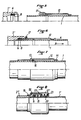
- This female connector has a bore 3 of diameter corresponding to the internal diameter of the tubular element 1 extended by a cylindrical seat 4 housing in connection position (FIG. 1) the end of the male tubular element, this seat being itself extended by a cylindrical seat of larger diameter 5 housing a seal 6 and a frustoconical seat 7 housing a spring ring 8.
- the frustoconical bearing 7 converging towards the outside is extended towards the end of the connector 2 by a cylindrical bearing 9 in a groove 10 of which an annular seal 11 is projecting.
- a disconnection sleeve 12 is provided mounted prisoner on the male tubular element, for this purpose comprising a recess 13 and a rear part deformed by crimping 14 limiting the movement of the sleeve 12 against a projecting bead 15 produced in this embodiment, by deformation of the wall of the male tubular element 1.
- the movement of the sleeve 12 is limited relative to an annular seal 16 housed in a groove provided at the periphery of the male tubular element 1.
- the seal 11 limits, as seen in Figure 1, the penetration of the sleeve 12 and also provides an additional sealing function.
- connection device is perfectly reusable. In case of need. it is of course possible to easily replace deteriorated components, in particular the seals.
- connection device differs only from that of the embodiment of Figures 1 to 3 by the fact that the female connector 2 ⁇ no longer has a groove 10 housing a seal and that the limiting function the advancement of the sleeve 12 is ensured by a bellows 17 secured to the end of the sleeve 12.
- This bellows in the connection position illustrated in FIG. 4, bears against the end of the female connector 2 ⁇ is likely to be crushed, as seen in Figure 6, when the sleeve 12 is pushed in the direction of arrow A in order to achieve disconnection. This is carried out in the same way as in the previous embodiment, then exerting traction in the direction materialized by the arrow B on the male tubular element 1.
- the mounting of the captive sleeve of the male tubular element 1 can also be carried out in the manner illustrated in FIG. 7.
- the male tubular element 1 ⁇ differs from the male tubular element 1 of the previous embodiments in that it has not undergone any particular preparation.
- the female connector 2 ⁇ has a recess at its outer wall at 18 and the disconnection sleeve 12 ⁇ is mounted captive to the female connector by presenting a folded end by crimping 19 and a curved end part 20 capable of engaging inside the female connector along the male tubular element 1 ⁇ .
- a ring for example made of PTFE (not shown) between the seal 6 and the spring ring 8.
- the effect of this ring is to prevent deterioration of the seal during aging.
Landscapes
- Engineering & Computer Science (AREA)
- General Engineering & Computer Science (AREA)
- Mechanical Engineering (AREA)
- Quick-Acting Or Multi-Walled Pipe Joints (AREA)
- Pipeline Systems (AREA)
- Cable Accessories (AREA)
- Joints Allowing Movement (AREA)
Claims (9)
- Kupplungsvorrichtung zum schnellen Verbinden und Trennen von Rohrleitungen, mit einem Steckrohr und einer Steckhülse einschl. einer Bohrung, deren Durchmesser dem inneren Durchmesser des Steckrohres entspricht und die in Richtung auf das Steckhülsenende mit Hilfe eines Abschnittes, dessen Durchmesser dem äußeren Durchmesser des Steckrohres entspricht, mit Hilfe eines zylindrischen Abschnittes mit einem wichtigeren Durchmesser, in dem eine Dichtung angeordnet ist, und mit Hilfe eines konischen Abschnittes verlängert ist, der sich in Richtung des Steckhülsenendes verjüngt und in dem Haltemittel angeordnet sind, die zum Festhalten des Steckrohres in der Steckhülse dienen, einer rohrförmigen äußeren Manschette (12, 12'), die unverlierbar auf dem Steckrohr (1) oder der Steckhülse (2, 2'') angebracht ist, entlang dem Steckrohr verschieblich angeordnet ist und einen Endabschnitt trägt, der in die Steckhülse (2, 2', 2'') eingreift, sowie mit einem elastisch deformierbaren Element (11, 17, 21), das so angeordnet ist, daß es bei der Annäherung der Manschette (12, 12') während der Verbindung einen Widerstand bietet, jedoch während einer weiteren Fortbewegung der Manschette unter der Wirkung einer axialen, vorgegebenen Druckkraft elastisch deformierbar ist, dergestalt, daß der Manschette bei einem Trennungsvorgang das Erreichen und Zurückschieben der Haltemittel in den zylindrischen Abschnitt des größeren Durchmessers (5) der Bohrung der Steckhülse gestattet wird, was die nachfolgende Trennung durch einfaches axiales Ziehen des Steckrohres aus der Steckhülse gestattet, dadurch gekennzeichnet, daß die Haltemittel einen Federring (8) umfassen, der in dem konischen, sich in Richtung auf das Steckschlüsselende verjüngenden Abschnitt angeordnet ist, daß für das Trennen die Manschette (12, 12') den Federring (8) in den zylindrischen Abschnitt des wichtigeren Durchmessers (5) der Bohrung der Steckhülse zurückdrückt, und daß das elastisch deformierbare Element (11, 17, 21) so angeordnet ist, daß es lediglich bei dem Vorschieben der Manschette (12, 12') einen Widerstand bietet, ohne den Federring (8) zu beeinflussen.
- Kupplungsvorrichtung nach Anspruch 1, dadurch gekennzeichnet, daß die äußere Manschette (12) unverlierbar auf dem Steckrohr (1) angebracht ist.
- Kupplungsvorrichtung nach Anspruch 2, dadurch gekennzeichnet, daß das Steckrohr einen Vorsprung (15, 16) aufweist, der sich von seiner äußeren Oberfläche abhebt, wobei die Manschette zu beiden Seiten des Vorsprungs zwischen den Positionen verschiebbar ist, die durch ihr hinteres Ende (14), das durch eine Einschnürung gegen das Steckrohr deformiert ist, und eine Stufe (13) festgelegt sind, die in ihrer inneren Wandung vorgesehen ist.
- Kupplungsvorrichtung nach Anspruch 3, dadurch gekennzeichnet, daß der Vorsprung durch eine Deformation (15) der Wandung des Steckrohrs nach außen gebildet ist.
- Kupplungsvorrichtung nach Anspruch 3, dadurch gekennzeichnet, daß der Vorsprung durch einen Sicherungsring (16) gebildet ist, der in einer Nut liegt, die am Umfang des Steckrohres vorgesehen ist.
- Kupplungsvorrichtung nach einem der vorhergehenden Ansprüche, dadurch gekennzeichnet, daß das elastisch deformierbare Element eine Ringdichtung (11) ist, die nach innen vorspringend in einer Nut (10) untergebracht ist, die nahe an dem Ende der Steckhülse (2) liegt.
- Kupplungsvorrichtung nach einem der Ansprüche 1 bis 5, dadurch gekennzeichnet, daß das elastisch deformierbare Element ein rohrförmiger Balg (17) ist, der an der Manschette (12) angebracht ist, in der Verbindungsposition gegen das Ende der Steckhülse (2') zur Anlage kommt und während des Eindrückens der Manschette in die Steckhülse für den Trennvorgang gegen dieses Ende zusammengedrückt wird.
- Kupplungsvorrichtung nach Anspruch 1, dadurch gekennzeichnet, daß die äußere Manschette (12') unverlierbar auf der Steckhülse (2'') angeordnet ist.
- Kupplungsvorrichtung nach Anspruch 8, dadurch gekennzeichnet, daß die Manschette (12') einen zurückgefalteten Endabschnitt (20) trägt, der in die Steckhülse eingreifen kann, wobei das elastisch deformierbare Element ein elastisches Element wie z.B. eine Schraubenfeder (21) ist, das in der Manschette um den zurückgefalteten Endabschnitt herumgelegt ist und axial an dem Ende (22) der Steckhülse anliegt.
Priority Applications (1)
| Application Number | Priority Date | Filing Date | Title |
|---|---|---|---|
| AT87402367T ATE78572T1 (de) | 1986-10-22 | 1987-10-21 | Kupplungsvorrichtung zum schnellen verbinden und loesen von rohrleitungen. |
Applications Claiming Priority (2)
| Application Number | Priority Date | Filing Date | Title |
|---|---|---|---|
| FR8614658A FR2605710B1 (fr) | 1986-10-22 | 1986-10-22 | Dispositif de raccordement, a connexion et deconnexion rapides, de conduites tubulaires |
| FR8614658 | 1986-10-22 |
Publications (2)
| Publication Number | Publication Date |
|---|---|
| EP0268511A1 EP0268511A1 (de) | 1988-05-25 |
| EP0268511B1 true EP0268511B1 (de) | 1992-07-22 |
Family
ID=9340066
Family Applications (1)
| Application Number | Title | Priority Date | Filing Date |
|---|---|---|---|
| EP87402367A Expired - Lifetime EP0268511B1 (de) | 1986-10-22 | 1987-10-21 | Kupplungsvorrichtung zum schnellen Verbinden und Lösen von Rohrleitungen |
Country Status (5)
| Country | Link |
|---|---|
| EP (1) | EP0268511B1 (de) |
| AT (1) | ATE78572T1 (de) |
| DE (2) | DE3780578D1 (de) |
| ES (1) | ES2011759A4 (de) |
| FR (1) | FR2605710B1 (de) |
Families Citing this family (7)
| Publication number | Priority date | Publication date | Assignee | Title |
|---|---|---|---|---|
| FR2648894B2 (fr) * | 1989-01-04 | 1991-08-16 | Legris Sa | Perfectionnements a une pince pour dispositif de raccordement instantane de conduit de fluide, et dispositifs pourvus d'une telle pince |
| GB2266569B (en) * | 1992-04-29 | 1995-07-12 | F W Talbot & Company Limited | A connector |
| DE19727538C2 (de) * | 1997-06-28 | 2001-05-17 | Hansa Metallwerke Ag | Schnellkupplung |
| US6155607A (en) * | 1998-02-17 | 2000-12-05 | Parker-Hannifin Corporation | Quick connect coupling |
| US7354079B2 (en) | 2002-04-23 | 2008-04-08 | Watts Sea Tech, Inc. | Connector |
| DE102014000387B4 (de) * | 2014-01-10 | 2015-07-30 | Oetiker Schweiz Ag | Schnellkupplung |
| CN106090472B (zh) * | 2016-08-09 | 2018-12-07 | 河南柴油机重工有限责任公司 | 一种柴油机油路管道连接装置 |
Family Cites Families (5)
| Publication number | Priority date | Publication date | Assignee | Title |
|---|---|---|---|---|
| US2111956A (en) * | 1937-01-27 | 1938-03-22 | Eclipse Machine Co | Automatic coupling |
| US2702202A (en) * | 1950-06-23 | 1955-02-15 | Aeroquip Corp | Packed-socket pipe coupling with releasable pipe retaining means |
| US3534776A (en) * | 1968-06-10 | 1970-10-20 | Lafayette E Gilreath | Sealed pipe joint and releasing means therefor |
| JPS59150087U (ja) * | 1983-03-26 | 1984-10-06 | 千代田通商株式会社 | ホ−スの継手 |
| GB2166508B (en) * | 1984-11-05 | 1989-04-05 | Paragon Plastics Limited | Pipe joints |
-
1986
- 1986-10-22 FR FR8614658A patent/FR2605710B1/fr not_active Expired
-
1987
- 1987-10-21 DE DE8787402367T patent/DE3780578D1/de not_active Expired - Lifetime
- 1987-10-21 AT AT87402367T patent/ATE78572T1/de not_active IP Right Cessation
- 1987-10-21 DE DE198787402367T patent/DE268511T1/de active Pending
- 1987-10-21 ES ES87402367T patent/ES2011759A4/es active Pending
- 1987-10-21 EP EP87402367A patent/EP0268511B1/de not_active Expired - Lifetime
Also Published As
| Publication number | Publication date |
|---|---|
| FR2605710B1 (fr) | 1989-01-20 |
| DE3780578D1 (de) | 1992-08-27 |
| DE268511T1 (de) | 1989-01-05 |
| FR2605710A1 (fr) | 1988-04-29 |
| ES2011759A4 (es) | 1990-02-16 |
| ATE78572T1 (de) | 1992-08-15 |
| EP0268511A1 (de) | 1988-05-25 |
Similar Documents
| Publication | Publication Date | Title |
|---|---|---|
| EP0488844B1 (de) | Anschlussvorrichtung, insbesondere zur Verbindung eines Schlauches mit einem Automobilwärmeaustauscher | |
| FR2931534A1 (fr) | Dispositif de raccord rapide pour des pressions elevees. | |
| FR2831642A1 (fr) | Coupleur | |
| EP0200666A1 (de) | Schnellverbindung für Rohre aus Kunststoff oder Metall | |
| EP1422461A1 (de) | Schnellkupplung zur trennbaren Verbindung von zwei Rohre | |
| FR2987097A1 (fr) | Dispositif de raccordement etanche sans zone de retention | |
| EP3184870A1 (de) | Buchse eines schnellanschlusses, und eine solche buchse umfassender schnellanschluss | |
| CA2408370A1 (fr) | Dispositif de raccordement d'un embout a un organe | |
| FR2810087A1 (fr) | Element pourvu exterieurement de moyens pour cooperer avec un taraudage | |
| EP1164327B1 (de) | Kupplung mit Verriegelungsschrägen | |
| FR2862740A1 (fr) | Dispositif de raccordement de canalisations | |
| FR2605710A1 (fr) | Dispositif de raccordement, a connexion et deconnexion rapides, de conduites tubulaires | |
| FR3156876A1 (fr) | Dispositif de raccordement fluidique et ensemble de raccordement fluidique comprenant un tel dispositif de raccordement fluidique | |
| FR2716241A1 (fr) | Vérin, notamment hydraulique, comportant un raccord de branchement sous forme de liaison à emmanchement. | |
| FR2758379A1 (fr) | Cartouche d'implantation pour un raccord d'un tuyau destine a prendre place dans un logement | |
| FR2674042A1 (fr) | Dispositif hydraulique et pneumatique de blocage. | |
| WO2010052386A1 (fr) | Dispositif de raccordement comportant un element d'etancheite | |
| FR2554543A1 (fr) | Raccord pour montage rapide d'un tube de tuyauterie dans un trou taraude | |
| EP0187608B1 (de) | Schnellverbindung für unter Druck stehende Flüssigkeitssysteme in denen der Druck 150 bar erreichen kann | |
| EP0364380B1 (de) | Anschlusssystem, insbesondere für unter hohem Druck stehende hydraulische Leitung | |
| EP1155255A1 (de) | Verbindungsvorrichtung für den anschluss einer leitung an ein element | |
| FR2788581A1 (fr) | Ensemble de connexion d'une extremite de conduite a un element | |
| FR2578621A1 (fr) | Dispositif de raccordement amovible pour tuyaux | |
| FR2827923A1 (fr) | Palier a roulement de colonne de direction pour vehicule automobile | |
| BE1005538A3 (fr) | Procede et dispositif de fixation liberable d'un embout male dans un element femelle correspondant. |
Legal Events
| Date | Code | Title | Description |
|---|---|---|---|
| PUAI | Public reference made under article 153(3) epc to a published international application that has entered the european phase |
Free format text: ORIGINAL CODE: 0009012 |
|
| AK | Designated contracting states |
Kind code of ref document: A1 Designated state(s): AT BE CH DE ES GB GR IT LI LU NL SE |
|
| GBC | Gb: translation of claims filed (gb section 78(7)/1977) | ||
| 17P | Request for examination filed |
Effective date: 19880923 |
|
| DET | De: translation of patent claims | ||
| RAP1 | Party data changed (applicant data changed or rights of an application transferred) |
Owner name: TRINOVA S.A. |
|
| ITCL | It: translation for ep claims filed |
Representative=s name: MODIANO & ASSOCIATI S.R.L. |
|
| 17Q | First examination report despatched |
Effective date: 19890906 |
|
| TCAT | At: translation of patent claims filed | ||
| GRAA | (expected) grant |
Free format text: ORIGINAL CODE: 0009210 |
|
| AK | Designated contracting states |
Kind code of ref document: B1 Designated state(s): AT BE CH DE ES GB GR IT LI LU NL SE |
|
| PG25 | Lapsed in a contracting state [announced via postgrant information from national office to epo] |
Ref country code: IT Free format text: LAPSE BECAUSE OF FAILURE TO SUBMIT A TRANSLATION OF THE DESCRIPTION OR TO PAY THE FEE WITHIN THE PRE;WARNING: LAPSES OF ITALIAN PATENTS WITH EFFECTIVE DATE BEFORE 2007 MAY HAVE OCCURRED AT ANY TIME BEFORE 2007. THE CORRECT EFFECTIVE DATE MAY BE DIFFERENT FROM THE ONE RECORDED.SCRIBED TIME-LIMIT Effective date: 19920722 Ref country code: NL Effective date: 19920722 Ref country code: GR Free format text: LAPSE BECAUSE OF FAILURE TO SUBMIT A TRANSLATION OF THE DESCRIPTION OR TO PAY THE FEE WITHIN THE PRESCRIBED TIME-LIMIT Effective date: 19920722 Ref country code: GB Effective date: 19920722 Ref country code: DE Effective date: 19920722 Ref country code: AT Effective date: 19920722 Ref country code: SE Effective date: 19920722 |
|
| REF | Corresponds to: |
Ref document number: 78572 Country of ref document: AT Date of ref document: 19920815 Kind code of ref document: T |
|
| REF | Corresponds to: |
Ref document number: 3780578 Country of ref document: DE Date of ref document: 19920827 |
|
| PG25 | Lapsed in a contracting state [announced via postgrant information from national office to epo] |
Ref country code: CH Effective date: 19921031 Ref country code: BE Effective date: 19921031 Ref country code: LI Effective date: 19921031 Ref country code: LU Free format text: LAPSE BECAUSE OF NON-PAYMENT OF DUE FEES Effective date: 19921031 |
|
| PG25 | Lapsed in a contracting state [announced via postgrant information from national office to epo] |
Ref country code: ES Free format text: LAPSE BECAUSE OF FAILURE TO SUBMIT A TRANSLATION OF THE DESCRIPTION OR TO PAY THE FEE WITHIN THE PRESCRIBED TIME-LIMIT Effective date: 19921102 |
|
| NLV1 | Nl: lapsed or annulled due to failure to fulfill the requirements of art. 29p and 29m of the patents act | ||
| GBV | Gb: ep patent (uk) treated as always having been void in accordance with gb section 77(7)/1977 [no translation filed] |
Effective date: 19920722 |
|
| BERE | Be: lapsed |
Owner name: S.A. TRINOVA Effective date: 19921031 |
|
| PLBE | No opposition filed within time limit |
Free format text: ORIGINAL CODE: 0009261 |
|
| STAA | Information on the status of an ep patent application or granted ep patent |
Free format text: STATUS: NO OPPOSITION FILED WITHIN TIME LIMIT |
|
| REG | Reference to a national code |
Ref country code: CH Ref legal event code: PL |
|
| 26N | No opposition filed |