EP0268519A1 - System zur Verarbeitung von im Rauschen eingebetteten Signalen und dessen Anwendung bei der Geschwindigkeitsmesstechnik mittels Laser-Interferenzstreifen - Google Patents
System zur Verarbeitung von im Rauschen eingebetteten Signalen und dessen Anwendung bei der Geschwindigkeitsmesstechnik mittels Laser-Interferenzstreifen Download PDFInfo
- Publication number
- EP0268519A1 EP0268519A1 EP87402454A EP87402454A EP0268519A1 EP 0268519 A1 EP0268519 A1 EP 0268519A1 EP 87402454 A EP87402454 A EP 87402454A EP 87402454 A EP87402454 A EP 87402454A EP 0268519 A1 EP0268519 A1 EP 0268519A1
- Authority
- EP
- European Patent Office
- Prior art keywords
- samples
- delaying
- signal
- multiplying
- coefficients
- Prior art date
- Legal status (The legal status is an assumption and is not a legal conclusion. Google has not performed a legal analysis and makes no representation as to the accuracy of the status listed.)
- Granted
Links
Images



Classifications
-
- G—PHYSICS
- G01—MEASURING; TESTING
- G01P—MEASURING LINEAR OR ANGULAR SPEED, ACCELERATION, DECELERATION, OR SHOCK; INDICATING PRESENCE, ABSENCE, OR DIRECTION, OF MOVEMENT
- G01P5/00—Measuring speed of fluids, e.g. of air stream; Measuring speed of bodies relative to fluids, e.g. of ship, of aircraft
- G01P5/26—Measuring speed of fluids, e.g. of air stream; Measuring speed of bodies relative to fluids, e.g. of ship, of aircraft by measuring the direct influence of the streaming fluid on the properties of a detecting optical wave
Definitions
- This invention relates to a device whereby a noise can be extracted from short duration periodic signals succeeding each other at random intervals.
- the device can be applied to fringe laser velocimetry in order to measure the instantaneous rate of flow of gases or liquids, using particles carried by the fluid as tracer, these particles having a dimension of around 1 micron and being most often introduced artificially.
- the invention concerns a system of processing signals whereby it is possible to detect and analyse in frequency, in real time, all short duration periodic signals drowned in a noise and whose instants of appearance are unforeseeable.
- test volume a network of interference fringes is formed at a given point in the flow referred to as "test volume", via the intersection of two laser beams.
- a particle passing in the test volume encounters successively the clear and obscure parts of the fringes and diffuses light in all directions.
- This modulated signal has a gaussian envelope significant of the distribution of the intensity of the luminous flux in the test volume.
- a more or less intensive noise b(t) is generally superposed on the signal s(t) according to the position of the test volume in relation to the walls guiding the flow, and according to the way in which the photomultiplier receives the luminous flux (prior or back diffusion, ).
- a digital spectral analysis can also be made, the analysis is made digitally either via a band-pass scanning filter, or via a battery of filters in-parallel.
- the system becomes more accurate but remains slow (if only one filter is used), or costly (in the event of the filter battery).
- a digital correlator can be used in real time to extra ct from the "useful signal plus white noise" sum, the periodic useful part.
- white noise only affects the first coefficient of the signal autocorrelation function, it is simply necessary to acquire the C n ⁇ 0 correlation to extract the signal from the noise.
- Average speed and turbulence intensity can be deduced directly from the autocorrelation function, but it is easier to firstly make the Fourier transform and determine these values from the power spectrum.
- the correlator commercialized by the firm MALVERN uses this principle, digitizing the signal on one bit only.
- the method most currently used in laser velocimetry of this type is the so-called "counting" method.
- the useful signal is detected by comparing its amplitude to a threshold and the frequency is measured by counting a high speed clock on a certain number of periods of the frequency to be measured.
- This method is relatively accurate (although limited by the maximum frequency of the counting clock: 500 MHz) but it no longer operates when the noise level rises. In fact the passages of the signal across 0 are no longer significant.
- a method via spectral analysis on activation is known in the prior art and is the subject of Dieter Pallek's article on the DFVLR "Fast digital data acquisition and analysis of LDA signals by means of a transient recorder and an array processor" published in the ICIASF'85 Record.
- a section of the signal is acquired, in pre-activated mode, whose duration corresponds approximately to the passage time of the particle across the test volume.
- a Fourier transform of the signal is made and its power spectrum calculated via a parallel computer called "array processor”.
- This method is relatively sturdy versus the noise but all the same requires that the presence of the useful signal results in an increase of the global level detectable via a threshold. This method is therefore difficult to apply when the signal/noise ratio is much reduced. Moreover the system is not very fast and is relatively costly.
- the signal is digitized on one bit, for the filtering it is digitized on two bits.
- the new process proposed remedies these two drawbacks in the event of it being possible to assume the noise as white: - the detection criterion is no longer a comparison to a threshold on the energy but to a threshold on the autocorrelation function of the signal, which offers nonnull values for delays different from 0 whereas that of the noise is null for these same conditions; the estimate of the frequency is made by discrete Fourier transform (DFT) scanning a restricted frequency range estimated roughly from the first passage across 0 of the autocorrelation function. The speed of each particle can therefore be calculated.
- DFT discrete Fourier transform
- a means of detecting a periodical signal s(t) drowned in white noise is to perform the autocorrelation function limited in practice to owing to the fact that the analysis duration is limited to T.
- s(t) corresponds to the output of the photomultiplier after high-pass filtering.
- C( ⁇ ) k ⁇ (0) + a ⁇ . exp (- ⁇ 2/2( ⁇ 2 ⁇ )2).cos ⁇ ⁇ (o) is a Dirac pulse centered at the origin (autocorrelation of the noise). It can be seen here that C( ⁇ ) has a periodic component cos ⁇ which has the same angular frequency as that of s(t). On C( ⁇ ), the leasurement of ⁇ will be more accurate because the whole noise is reduced to the origin in the form of a Dirac pulse.
- the aim of the invention is to use the correlation method but modifying it so as to be able to store the instantaneous speeds.
- an autocorrelation function is calculated sliding with the time and whose integration duration T is constant and of the order of magnitude of the duration of a "burst".
- T 2 ⁇ M with ⁇ M mean standard deviation of the gaussian envelope of the "burst”.
- C n (i,k) is the present correlation coefficient for a delay k ⁇ t, calculated on a l time sector of duration n ⁇ t the origin of this sector being i-n ⁇ t with x i ⁇ 0 for i ⁇ 0.
- the fringe laser velocimeter includes a laser source 1 producing a coherent beam 2. This beam is divided into two beams 3 and 4 which are placed in interference in the test volume 5. The luminous flux emitted by the test volume 5 is received on a mirror 6 which projects it on to a photomultiplier 7. The output of the photomultiplier 7 is coupled to a signal processor unit 100.
- the invention concerns the structure of this processor unit.
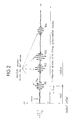
- FIG. 2 shows four "bursts" 101 to 104.
- the integration duration T runs from (t-T) to t and finishes at the present instant t.
- the duration T can be stated (t0 - t) - [t0 - (t - T)] or: (t0 - t) - [(t0+T) - t]
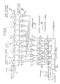
- Figure 3 shows in block diagram form, a correlation to calculate the relation (5).
- An analog/digital converter 10 samples and digitizes the signal on q bits. I.e., x i is output of the instant i ⁇ t ( ⁇ t sampling period).
- a shift register 11 initially resets and containing 2n stages 111 to 11 2n stores all the delayed samples.
- Output 130 of each of these subtractors 131 to 13 n is integrated digitally by integrators 141 to 14 n .
- the originality of the autocorrelator in Figure 3 is the existence of the stages 11 n+1 to 11 2n of register 11, of the multipliers 12 n+1 to 12 2n and subtractors 131 to 13 n .
- the criterion detecting the presence of a "burst" is the following:
- C1 will be chosen, to compare it in a comparator 15 to a preprogrammed threshold S. If C1 > S, comparator 15 will activate the memorization in store 16 of the n correlation coefficients. One will then wait for C1 to drop below the threshold to reset the system.
- Figure 5 shows again the out-leads 140 from integrators 141 to 143 and the correlation coefficients storage registers 16. Leads 140 are connected to amplitude detectors 171, 172, 173 and the outputs of these detectors are connected to an addition circuit 18 itself connected to comparator 15. The comparator controls read of register 16 as in Figure 3.
- the time ⁇ o after which the correlation function passes the first time across 0 is measured.
- the n correlation coefficients C1 to C n are memorized in store 16 (figure 3).
- a table 21 contains the values of the cos 2 ⁇ fk ⁇ t for k varying from of 1 to n and f varying from f1 to f2 by a pitch of ⁇ f (f1 and f2 are the limit frequencies corresponding to the limit speed contained in the flow and ⁇ f the frequential resolution to be obtained).
- f1 and f2 are the limit frequencies corresponding to the limit speed contained in the flow and ⁇ f the frequential resolution to be obtained).
- a table 21 address selection logic 22 initialized by f o - 1/2 ⁇ 0 will select a certain number of sub-stores whose frequencies frame f o .
- the integral product will be made via a multiplier 23 in digital integrator 24.
- the maximum of P(f) will correspond to the value f sought.
- the duration of this search obviously depends on the frequential pitch adopted but, with a frequency resolution of around 10 ⁇ 3, a real time rate of around a few kHz is possible.
- Digital integrator 24 is connected to a maximum search circuit 25 which is itself connected to the address selection logic 22 and to a gate 26 on output whereof the frequency sought is found.
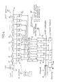
- the correlator in Figure 4 corresponds to the case in which it suffices, to estimate a correlation function, to digitize the signal s(t) on one bit, i.e., for example: 1 if s(t) > 0 O if s(t) ⁇ 0.
- the analog/digital converter 10 ⁇ is a one bit converter.
- Register 11 ⁇ is a one bit shift register.
- Multipliers 12 are replaced by simple "OR exclusive” circuits 12 ⁇ .
- Subtractors 13 are also replaced by "OR exclusive” circuits 13 ⁇ .
- the digital integrators 14 are counters - reverse counters in Figure 4. These counters - reverse counters are latched by the subtractor OR exclusive and driven by an input receiving the signal delivered by see Figure 4).
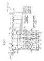
- Figure 7 shows a q x 1 bit correlator.
- Signal s(t) is digitized on q bits and the samples are stored in the different elements 111 to 11 2n of the shift register 11.
- the bit with which the q bits of the signal samples are correlated, is the most significant bit (sign) extracted from input 1101 of store 111 and input 110 n+1 of store 11 n+1 .
- S i and S i-n are the sign bits on inputs 1101 and 110 n+1 . According to the values of S i and S i-n it will therefore be necessary to calculate: x i-k - x i-n-k x i-k + x i-n-k -x i-k -x i-n-k + x i-n-k
- the adders - subtractors 301 to 30 n are set on addition or subtraction according to the sign of the sign bits S i and S i-n .
- the outputs of these adders - subtractors are connected to the inputs of digtial integrators 141 to 14 n as in the case in Figure 3.
- the single bit correlated in correlator 41 is taken on lead 51 corresponding to the most significant bit of line 50 transmitting the q bits and the single bit correlated in correlator 42 is taken on lead 52 corresponding to the bit of significance immediately below, of this line.
- the outputs of correlater 42 are added with the outputs of correlator 41 in adders 43 after having been shifted by one bit in circuit 44; this shift corresponding to a multiplication by 2 of the values of the output words of correlator 42.
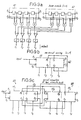
- Figure 9c shows two correlators 63, 64 with four autocorrelation coefficients C1, C2, C3, C4 and C5, C6, C7, C8, working in series to double the number of autocorrelation coefficients calculated.
- Each correlator contains two shift registers 611, 621 and 612, 622; the first two registers 611, 612 and the second two registers 621, 622 being grouped and connected in series to form two double capacity registers, storing respectively the delayed samples of ⁇ t, 2 ⁇ t, ..., n ⁇ t and those delayed, from (n+1) ⁇ t, (n+2) ⁇ t, ..., 2n ⁇ t.
- correlation units are provided supplying px4 correlation coefficients, by a serial connection of p correlators.
Landscapes
- Engineering & Computer Science (AREA)
- Multimedia (AREA)
- Aviation & Aerospace Engineering (AREA)
- Physics & Mathematics (AREA)
- General Physics & Mathematics (AREA)
- Complex Calculations (AREA)
Applications Claiming Priority (2)
| Application Number | Priority Date | Filing Date | Title |
|---|---|---|---|
| FR8615250 | 1986-10-31 | ||
| FR8615250A FR2606157B1 (fr) | 1986-10-31 | 1986-10-31 | Systeme de traitement de signaux noyes dans un bruit et son application en velocimetrie laser a franges |
Publications (2)
| Publication Number | Publication Date |
|---|---|
| EP0268519A1 true EP0268519A1 (de) | 1988-05-25 |
| EP0268519B1 EP0268519B1 (de) | 1990-06-27 |
Family
ID=9340439
Family Applications (1)
| Application Number | Title | Priority Date | Filing Date |
|---|---|---|---|
| EP87402454A Expired EP0268519B1 (de) | 1986-10-31 | 1987-10-30 | System zur Verarbeitung von im Rauschen eingebetteten Signalen und dessen Anwendung bei der Geschwindigkeitsmesstechnik mittels Laser-Interferenzstreifen |
Country Status (5)
| Country | Link |
|---|---|
| US (1) | US4899289A (de) |
| EP (1) | EP0268519B1 (de) |
| DE (1) | DE3763459D1 (de) |
| DK (1) | DK569387A (de) |
| FR (1) | FR2606157B1 (de) |
Cited By (3)
| Publication number | Priority date | Publication date | Assignee | Title |
|---|---|---|---|---|
| FR2708744A1 (fr) * | 1993-07-14 | 1995-02-10 | Saint Louis Inst | Procédé et dispositif de traitement du signal. |
| FR2749943A1 (fr) * | 1996-06-18 | 1997-12-19 | Sextant Avionique | Sonde velocimetrique optique |
| WO2006077559A3 (en) * | 2005-01-21 | 2006-10-12 | Koninkl Philips Electronics Nv | Method and apparatus for detecting the presence of a digital television signal |
Families Citing this family (13)
| Publication number | Priority date | Publication date | Assignee | Title |
|---|---|---|---|---|
| US5065334A (en) * | 1989-04-28 | 1991-11-12 | Hewlett-Packard Company | Method and apparatus for distinguishing narrowband continuous wave signals from broadband and impulsive signals |
| GB2232241B (en) * | 1989-05-27 | 1993-06-02 | Schlumberger Ltd | Method for determining dynamic flow characteristics of multiphase flows |
| US5434385A (en) * | 1992-11-02 | 1995-07-18 | International Business Machines Corporation | Dual channel D.C. low noise measurement system and test methodology |
| US5453834A (en) * | 1994-04-11 | 1995-09-26 | Evenstad; James O. | Digital burst frequency translator |
| US5479440A (en) * | 1994-04-15 | 1995-12-26 | Gas Research Institute | Apparatus and method for impulsive noise cancellation |
| US5793323A (en) * | 1996-11-25 | 1998-08-11 | The United States Of America As Represented By The Secretary Of The Air Force | Two signal monobit electronic warfare receiver |
| US6477476B1 (en) * | 1999-12-06 | 2002-11-05 | Koninklijke Philips Electronics N.V. | Periodic-signal analysis via correlation |
| US6751564B2 (en) | 2002-05-28 | 2004-06-15 | David I. Dunthorn | Waveform analysis |
| WO2008133679A1 (en) * | 2007-04-26 | 2008-11-06 | University Of Florida Research Foundation, Inc. | Robust signal detection using correntropy |
| CA2657087A1 (en) * | 2008-03-06 | 2009-09-06 | David N. Fernandes | Normative database system and method |
| CA2685779A1 (en) * | 2008-11-19 | 2010-05-19 | David N. Fernandes | Automated sound segment selection method and system |
| JP6477295B2 (ja) * | 2015-06-29 | 2019-03-06 | 株式会社Jvcケンウッド | 雑音検出装置、雑音検出方法及び雑音検出プログラム |
| FR3129000B1 (fr) * | 2021-11-09 | 2025-01-10 | Commissariat Energie Atomique | Détecteur de rayonnement ionisant comportant un modulateur pour moduler l’intensité du rayonnement |
Citations (2)
| Publication number | Priority date | Publication date | Assignee | Title |
|---|---|---|---|---|
| FR2303296A1 (fr) * | 1975-03-05 | 1976-10-01 | Saint Louis Inst | Dispositif pour l'exploitation de signaux periodiques de duree limitee se succedant a intervalles aleatoires |
| EP0097041A2 (de) * | 1982-06-11 | 1983-12-28 | The Babcock & Wilcox Company | Korrelation von Rauschsignalen |
Family Cites Families (4)
| Publication number | Priority date | Publication date | Assignee | Title |
|---|---|---|---|---|
| US3621220A (en) * | 1969-08-29 | 1971-11-16 | Norman C Ford Jr | Scattered light measurement providing autocorrelation function |
| US3646333A (en) * | 1969-12-12 | 1972-02-29 | Us Navy | Digital correlator and integrator |
| DE2818768C2 (de) * | 1978-04-28 | 1986-07-24 | Hewlett-Packard GmbH, 7030 Böblingen | Verfahren und Vorrichtung zum Messen der Frequenz bzw. der Periodendauer der Grundschwingung eines annähernd periodischen Eingangssignales |
| US4786168A (en) * | 1986-11-24 | 1988-11-22 | The United States Of America As Represented By The United States National Aeronautics And Space Administration | Frequency domain laser velocimeter signal processor |
-
1986
- 1986-10-31 FR FR8615250A patent/FR2606157B1/fr not_active Expired
-
1987
- 1987-10-30 EP EP87402454A patent/EP0268519B1/de not_active Expired
- 1987-10-30 DE DE8787402454T patent/DE3763459D1/de not_active Expired - Lifetime
- 1987-10-30 US US07/114,748 patent/US4899289A/en not_active Expired - Fee Related
- 1987-10-30 DK DK569387A patent/DK569387A/da not_active Application Discontinuation
Patent Citations (2)
| Publication number | Priority date | Publication date | Assignee | Title |
|---|---|---|---|---|
| FR2303296A1 (fr) * | 1975-03-05 | 1976-10-01 | Saint Louis Inst | Dispositif pour l'exploitation de signaux periodiques de duree limitee se succedant a intervalles aleatoires |
| EP0097041A2 (de) * | 1982-06-11 | 1983-12-28 | The Babcock & Wilcox Company | Korrelation von Rauschsignalen |
Non-Patent Citations (2)
| Title |
|---|
| THE RADIO AND ELECTRONIC ENGINEER, vol. 43, no. 6, June 1973, pages 363-368, London, GB; A.M. HAYES et al.: "Correlator design for flow measurement" * |
| THIRD INTERNATIONAL SYMPOSIUM ON APPLICATIONS OF LASER ANEMOMETRY TO FLUID MECHANICS, Lisbon, 7th-9th July 1986, pages 3.1.1 - 3.6.6; J.F. MEYERS et al.: "Frequency domain laser velocimeter signal processor" * |
Cited By (5)
| Publication number | Priority date | Publication date | Assignee | Title |
|---|---|---|---|---|
| FR2708744A1 (fr) * | 1993-07-14 | 1995-02-10 | Saint Louis Inst | Procédé et dispositif de traitement du signal. |
| FR2749943A1 (fr) * | 1996-06-18 | 1997-12-19 | Sextant Avionique | Sonde velocimetrique optique |
| EP0814340A1 (de) * | 1996-06-18 | 1997-12-29 | Sextant Avionique | Optische Geschwindigkeitssonde |
| US5859694A (en) * | 1996-06-18 | 1999-01-12 | Sextant Avionique | Optical velocimeter probe |
| WO2006077559A3 (en) * | 2005-01-21 | 2006-10-12 | Koninkl Philips Electronics Nv | Method and apparatus for detecting the presence of a digital television signal |
Also Published As
| Publication number | Publication date |
|---|---|
| DK569387A (da) | 1988-05-01 |
| FR2606157B1 (fr) | 1989-01-06 |
| US4899289A (en) | 1990-02-06 |
| DE3763459D1 (de) | 1990-08-02 |
| DK569387D0 (da) | 1987-10-30 |
| FR2606157A1 (fr) | 1988-05-06 |
| EP0268519B1 (de) | 1990-06-27 |
Similar Documents
| Publication | Publication Date | Title |
|---|---|---|
| EP0268519B1 (de) | System zur Verarbeitung von im Rauschen eingebetteten Signalen und dessen Anwendung bei der Geschwindigkeitsmesstechnik mittels Laser-Interferenzstreifen | |
| US4164036A (en) | Quadrature correlation phase reversal pulse detector | |
| EP0660124A2 (de) | Einrichtung und Verfahren zum Messen von Phasenrauschen | |
| Ransom et al. | A new search technique for short orbital period binary pulsars | |
| US5005144A (en) | Signal processing system for flow velocity in laser doppler velocimeter | |
| US4542657A (en) | Time domain technique to determine mean frequency | |
| US4162630A (en) | Measurement and reconstruction of three-dimensional fluid flow | |
| US5805460A (en) | Method for measuring RF pulse rise time, fall time and pulse width | |
| EP0125838B1 (de) | Peiler | |
| US3733892A (en) | Synchronous vibrational analyzer for rotating machinery | |
| US4730257A (en) | Apparatus for analyzing signals, to obtain parameters of constituents | |
| US5818735A (en) | Method and system for high resolution time-of-flight measurements | |
| US4583409A (en) | Method for measuring the flow parameters of a fluid and device utilizing the method | |
| US4619267A (en) | Method for characterizing the structure of a medium and device for carrying out the method | |
| Veyuante et al. | Application of nonlinear spectral analysis and signal reconstruction to laser Doppler velocimetry | |
| EP0511213B1 (de) | Vorrichtung und verfahren zur detektion eines bursts mit kohärenter frequenz | |
| Rudnick | The detection of weak signals by correlation methods | |
| US3987443A (en) | Radar | |
| US4545025A (en) | Auto covariance computer | |
| RU2117954C1 (ru) | Измеритель отношения сигнал-шум | |
| US5844144A (en) | Method for estimating flow velocity | |
| Grechikhin et al. | Hilbert transform for processing of laser Doppler vibrometer signals | |
| Sirmans et al. | Pulsed-Doppler velocity isotach displays of storm winds in real time | |
| Ibrahim et al. | Signal processing considerations for low signal to noise ratio laser Doppler and phase Doppler signals | |
| RU2799002C1 (ru) | Способ моноимпульсного измерения радиальной скорости объектов |
Legal Events
| Date | Code | Title | Description |
|---|---|---|---|
| PUAI | Public reference made under article 153(3) epc to a published international application that has entered the european phase |
Free format text: ORIGINAL CODE: 0009012 |
|
| AK | Designated contracting states |
Kind code of ref document: A1 Designated state(s): BE DE GB IT NL |
|
| 17P | Request for examination filed |
Effective date: 19881115 |
|
| 17Q | First examination report despatched |
Effective date: 19891030 |
|
| GRAA | (expected) grant |
Free format text: ORIGINAL CODE: 0009210 |
|
| AK | Designated contracting states |
Kind code of ref document: B1 Designated state(s): BE DE GB IT NL |
|
| REF | Corresponds to: |
Ref document number: 3763459 Country of ref document: DE Date of ref document: 19900802 |
|
| ITF | It: translation for a ep patent filed | ||
| PGFP | Annual fee paid to national office [announced via postgrant information from national office to epo] |
Ref country code: DE Payment date: 19901011 Year of fee payment: 4 |
|
| PGFP | Annual fee paid to national office [announced via postgrant information from national office to epo] |
Ref country code: NL Payment date: 19901031 Year of fee payment: 4 |
|
| PLBE | No opposition filed within time limit |
Free format text: ORIGINAL CODE: 0009261 |
|
| STAA | Information on the status of an ep patent application or granted ep patent |
Free format text: STATUS: NO OPPOSITION FILED WITHIN TIME LIMIT |
|
| 26N | No opposition filed | ||
| PGFP | Annual fee paid to national office [announced via postgrant information from national office to epo] |
Ref country code: GB Payment date: 19910919 Year of fee payment: 5 |
|
| PGFP | Annual fee paid to national office [announced via postgrant information from national office to epo] |
Ref country code: BE Payment date: 19911022 Year of fee payment: 5 |
|
| ITTA | It: last paid annual fee | ||
| PG25 | Lapsed in a contracting state [announced via postgrant information from national office to epo] |
Ref country code: NL Effective date: 19920501 |
|
| NLV4 | Nl: lapsed or anulled due to non-payment of the annual fee | ||
| PG25 | Lapsed in a contracting state [announced via postgrant information from national office to epo] |
Ref country code: DE Effective date: 19920701 |
|
| PG25 | Lapsed in a contracting state [announced via postgrant information from national office to epo] |
Ref country code: GB Effective date: 19921030 |
|
| PG25 | Lapsed in a contracting state [announced via postgrant information from national office to epo] |
Ref country code: BE Effective date: 19921031 |
|
| BERE | Be: lapsed |
Owner name: OFFICE NATIONAL D'ETUDES ET DE RECHERCHES AEROSPAT Effective date: 19921031 |
|
| GBPC | Gb: european patent ceased through non-payment of renewal fee |
Effective date: 19921030 |
|
| PG25 | Lapsed in a contracting state [announced via postgrant information from national office to epo] |
Ref country code: IT Free format text: LAPSE BECAUSE OF NON-PAYMENT OF DUE FEES;WARNING: LAPSES OF ITALIAN PATENTS WITH EFFECTIVE DATE BEFORE 2007 MAY HAVE OCCURRED AT ANY TIME BEFORE 2007. THE CORRECT EFFECTIVE DATE MAY BE DIFFERENT FROM THE ONE RECORDED. Effective date: 20051030 |