EP0268540A1 - Bodenbearbeitungsmaschine - Google Patents
Bodenbearbeitungsmaschine Download PDFInfo
- Publication number
- EP0268540A1 EP0268540A1 EP87440068A EP87440068A EP0268540A1 EP 0268540 A1 EP0268540 A1 EP 0268540A1 EP 87440068 A EP87440068 A EP 87440068A EP 87440068 A EP87440068 A EP 87440068A EP 0268540 A1 EP0268540 A1 EP 0268540A1
- Authority
- EP
- European Patent Office
- Prior art keywords
- machine according
- working machine
- soil working
- arms
- bars
- Prior art date
- Legal status (The legal status is an assumption and is not a legal conclusion. Google has not performed a legal analysis and makes no representation as to the accuracy of the status listed.)
- Granted
Links
- 239000002689 soil Substances 0.000 claims description 45
- 230000008878 coupling Effects 0.000 claims description 9
- 238000010168 coupling process Methods 0.000 claims description 9
- 238000005859 coupling reaction Methods 0.000 claims description 9
- 238000003971 tillage Methods 0.000 claims description 8
- 230000001131 transforming effect Effects 0.000 claims description 2
- 239000013013 elastic material Substances 0.000 claims 2
- 230000005540 biological transmission Effects 0.000 description 2
- 230000000694 effects Effects 0.000 description 2
- 230000010363 phase shift Effects 0.000 description 2
- 238000005096 rolling process Methods 0.000 description 2
- 230000007935 neutral effect Effects 0.000 description 1
- 230000000149 penetrating effect Effects 0.000 description 1
- 230000035515 penetration Effects 0.000 description 1
- 230000003068 static effect Effects 0.000 description 1
Images


Classifications
-
- A—HUMAN NECESSITIES
- A01—AGRICULTURE; FORESTRY; ANIMAL HUSBANDRY; HUNTING; TRAPPING; FISHING
- A01B—SOIL WORKING IN AGRICULTURE OR FORESTRY; PARTS, DETAILS, OR ACCESSORIES OF AGRICULTURAL MACHINES OR IMPLEMENTS, IN GENERAL
- A01B19/00—Harrows with non-rotating tools
- A01B19/02—Harrows with non-rotating tools with tools rigidly or elastically attached to a tool-frame
- A01B19/06—Harrows with non-rotating tools with tools rigidly or elastically attached to a tool-frame with tools or tool-frames moved to-and-fro mechanically
Definitions
- the invention described below relates to a soil working machine comprising on the one hand a chassis provided with a coupling device to a tractor vehicle, chassis to which are linked by a plurality of swing arms at least two rows of one or more bars provided with tools, said rows being arranged one behind the other and transverse to the direction of advance, and on the other hand a device for transforming the rotary movement received from the power take-off of the towing vehicle in a reciprocating movement transverse to the direction of advance comprising a device of eccentric connecting rods, said connecting rods serving to transmit the reciprocating movement to the bars to which they are linked by one of their ends.
- the object of the present invention is to solve the aforementioned problem raised on the existing machine.
- the soil working machine according to the invention is characterized in that the oscillating arms of the bars facing each other in different rows are, seen in a direction transverse to the advancement of said working machine of the ground, mounted substantially side by side.
- This arrangement thus makes it possible to considerably reduce the size of the chassis considered in the direction of advance of the machine.
- said oscillating arms of the front row are directed downwards and forward and said rear row swing arms are directed downward and backward to be linked to their respective bar.
- the upper attachments of the swinging arms are widened as much as possible so as to optimally distribute the high stresses resulting from the working conditions of the soil.
- the oscillating arms appear as intersecting when viewed transversely to the direction of advance.
- This shape of the swinging arms thus makes it possible to have a connection between the lower attachment of a swinging arm and its upper attachment which is substantially centered on said upper attachment and thus cooperates in the best distribution of the stresses generated during work.
- the lowest point of intersection of said side-by-side oscillating arms is located as close as possible to the upper attachment. This makes it possible to avoid to a large extent the jamming of stones between these oscillating arms which have a pendular movement transverse to the direction of advance.
- the chassis can be arranged more higher or lower than the upper attachments of the swing arms.
- the chassis will be located lower than the upper attachments of the swinging arms, which will reduce the overall height of the machine.
- the width of the chassis considered in the direction of advance is substantially equal to the distance measured in the direction of advance between the outer ends of the lower fasteners of two side-by-side oscillating arms.
- said soil working machine is equipped with a support and / or leveling device.
- This support and / or leveling device may be placed at the front and / or at the rear of the machine.
- FIG 1 we see a soil working machine according to the present invention.
- Said machine consists of a chassis (1) to which bars (2, 3, 4, 5) are linked by means of oscillating arms (6, 7) articulated at one of their ends in screeds (8) integral of said chassis (1) and at the other of their ends in yokes (9) integral with the respective bars (2, 3, 4, 5).
- the oscillating arms (6, 7) will be described in more detail later.
- the eccentric link device (10) will be described in more detail later.
- Each bar (2, 3, 4, 5) is provided with a certain number of working tools such as for example teeth (11) detachably fixed on the bars (2, 3, 4, 5). These teeth (11) are directed from said bars (2, 3, 4, 5), from top to bottom.
- the machine is also equipped with a coupling device (12) enabling it to be fixed, for example, to the three-point coupling system of a towing vehicle (13) (partially shown in FIG. 2).
- the coupling device (12) of the machine meanwhile has two lower coupling points (19, 20) intended to be connected to the two lower arms (16, 17) and an upper coupling point (21) intended to be linked to the upper connecting rod (18).
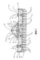
- the frame (1) is made up of two beams (22, 23) substantially parallel and extending transversely to the direction of advance (24). At each of their ends, the two beams (22, 23) are linked together by a side plate (25) so as to form a rigid assembly.
- the oscillating arms (6, 7) extend downward through the space between the two beams (22, 23) to reach their respective tooth bars (2, 3 , 4, 5).
- a cover (33) (partially seen at the ends of the machine) in order to protect the user from moving parts.
- Said soil working machine shown in this view is equipped with a rear leveling roller (34) known to those skilled in the art.
- This roller is linked in an articulated manner to the chassis (1) of the machine using arms (35) linked at their front end to the plates (25) by means of an axis joint directed transversely to the direction of advance (24) of the machine.
- the width of the roller (34) is substantially equal to the working width of the rows (27, 28) of tooth bars (2, 3, 4, 5).
- a support and leveling roller (36).
- This roller is linked to the chassis (1) of the machine by a connecting device (37) making it possible to adjust the height of said roller (36) relative to the tooth bars (2, 3, 4, 5).
- the width of this roller is at least equal to the track of the rear wheels (14, 15) of the towing vehicle (13).
- the oscillating arms (6, 7) are grouped in pairs. These pairs consist of a swing arm (6) and a swing arm (7) and in each of these pairs the upper fasteners (26) integral with their respective swing arms (6, 7) are as close as possible l one of the other.
- the input shaft (39) supports the eccentrics (41, 42) associated with the tooth bars (3, 2) of the front row (27), while at behind said bearing (40), the input shaft (39) supports the two eccentrics (43, 44) associated with the tooth bars (5, 4) of the rear row (28).
- the input shaft (39) is extended by the end of the shaft (38) described above.
- the two beams (22, 23) forming the chassis (1) of said machine, as well as a swing arm (7) linked to a tooth bar (2 or 3) of the front row (27 ) as well as a swing arm (6) linked to a tooth bar (4 or 5) of the rear row (28).
- this figure shows the way in which the oscillating arms (6, 7) pass through the space extending between the two beams (22, 23) of the chassis (1).
- the teeth (11) are mounted alternately at the front and at the rear of said tooth bars (2, 3).
- the tooth bars (4, 5) of the rear row (28) all the teeth (11) are mounted at the rear of said tooth bars (4, 5).
- Said soil working machine is also shown there equipped with the front roller (36).
- the connecting device (37) of the front roller (36) on the frame (1) of the machine consists of an arm (48) extending at each end of the roller (36) and a respective sleeve (49) , integral with said chassis (1).
- the roller (36) is guided in rotation at the lower end of said arms (48).
- the upper end of said arms (48) is introduced into its respective sleeve (49) and is held there axially by means of a pin (50) collaborating with one of the holes (51) of said sleeve 49).
- a rear hitch (52) allowing the addition of an accessory device to the rear of said machine.
- This rear coupling consists on the one hand of a frame (53) rigidly mounted on the soil working machine and on the other hand of a connecting rod (54) fixed in an articulated manner on the upper part of this frame (53) and two lower arms (55) also hingedly attached to the frame (53). The movement of these lower arms (55) is limited downwards by means of a chain (56), fixed to the lower arms (55) and to the frame (53).
- the connecting rod (54) and the arms lower (55) thus form a three-point hitch system.
- the chassis (1) of the soil working machine consists of a single beam (57) situated above the upper fixings (26) of the swinging arms (6, 7).
- the yokes (58) used to link the upper fixings (26) of the swinging arms (6, 7) to the frame (1), are fixed on the underside of said beam (57) and are open downwards.
- the teeth (11) of the rear tooth bars (4, 5) are mounted at the front of said tooth bars (4, 5). Note however that the distance between the rear teeth (11) of the front tooth bars (2, 3) and the teeth (11) of the rear tooth bars (4, 5) remains substantially the same as in the example of the figures 1 to 3.
- the beam (57) also serves as a bearing for the input shaft (39) of said eccentric connecting rod device (10). At the front of the beam (57) are fixed on the input shaft (39), the eccentrics (41, 42) associated with the front tooth bars (3, 2) while at the rear of said beam (57) extend the eccentrics (43, 44) associated with the rear tooth bars (5, 4).
- the beam (57) comprises at each of its ends a side plate (25).
- the rear roller (45) is hingedly linked to the side plates (25) by means of two arms (35).
- These side plates (25) comprise as described above, in their upper rear part of the holes (46) and in their lower part a stop (47).
- a pin (59) pressed into one of the holes (46) of each side plate (25) cooperates with the arm (35) of the respective roller (45) to limit the movement of the latter upwards.
- FIG. 5 one sees completely in section one of the swinging arms (6) linked to one of the rear tooth bars (4, 5) and in the background partially obscured one of the swinging arms (7) linked to one of the bars to front teeth (2, 3).
- the upper attachment of the swinging arms (6, 7) (here that of the swinging arm (6)) occupies substantially all the space available between the two beams (22, 23) of the chassis (1).
- the yokes (8) are located above the beams (22, 23). This allows in particular to save in height the size of these beams (22, 23).
- the upper attachment of the swing arm (6) consists on the one hand of a tubular member (60) integral with the swing arm (6), mounted concentrically to an axis (62). This axis (62) is linked by means of attachment (61) to the half-yokes constituting the yoke (8) integral with the chassis (1).
- Said axis (62) is linked to the tubular member (60) by an elastic device at each of its ends.
- Each elastic device consists of an inner tube (63), mounted tight on the inner axis (62) and an outer tube (64) mounted tight in one of the bores (65) made for this purpose at each end of the tubular member (60).
- the inner tube (63) is connected to the outer tube (64) by an elastic cylinder (66). This elastic device allows a certain rotation of the swinging arm (6) around the axis (62).
- the lower attachment of the swinging arm (6) consists on the one hand of a tubular member (67) connected to the swinging arm (6) and mounted concentrically to an axis (68).
- the axis (68) is connected by connecting means (69) to a yoke (9) secured to a tooth bar (4, 5).
- Said axis (68) is linked to the tubular member (67) by an elastic device at each of its ends.
- Said elastic devices respectively consist of an inner tube (71) mounted tight on the axis (68) and an outer tube (72) mounted tight in the tubular member (67).
- Each inner tube (71) is linked to its respective outer tube (72) by an elastic cylinder (73) also allowing a certain rotation of the oscillating arm (6) around the axis (68).
- a rear swing arm (6) has its lower tubular member (67) offset rearwardly from its upper tubular member (60) so that it can be linked to one of the rear tooth bars (4, 5).
- the upper tubular member (60) and the lower tubular member (67) of the same rear swinging arm (6) are linked together by a core (74) extending backwards and towards the bottom.
- this core (74) is wider in its upper part than in its lower part. It can also be seen that the connection of the core (74) to the upper tubular member (60) is substantially centered with respect to said upper tubular member (60).
- a front swinging arm (7) on the other hand intended to be linked to a front tooth bar (2, 3), has its lower tubular member (67) offset forward relative to its upper tubular member (60) in order to be able to be linked to one of the front tooth bars (2, 3).
- the upper tubular member (60) and the lower tubular member (67) of the same oscillating arm (7) are linked together by a core (741) extending forward and towards the bottom. In its upper part the core (741) is also wider than in its lower part. Likewise the connection of the core (741) to the upper tubular member (60) is also substantially centered with respect to said tubular member. upper (60).
- the cores (74, 741) of the oscillating arms (6, 7) appear as secants.
- the point of intersection (75) is located as high as possible relative to the bars. teeth (2, 3, 4, 5).
- the width (76) measured in the direction of advance (24) between the two beams (22, 23) of the frame (1) is substantially equal to the distance (77) measured in the direction in advance (24) between the outer ends of the lower tubular members (67) of the oscillating arms (6, 7).
- connecting rods (32, 31, 30, 29) are fixed as it is shown in this figure 6 by joints (78) to yokes (79), themselves integral with their respective tooth bar (3, 2, 5, 4).
- These connecting rods (32, 31, 30, 29) have a plane of symmetry (110) containing the axis of their corresponding articulation (78).
- the yokes (79) extend at the inner end of the tooth bars (3, 2, 5, 4) of which they are integral.
- the articulations (78) of the connecting rods (32, 31, 30, 29) on the corresponding yokes (79), are located at a certain height in relation to the tooth bars (3, 2, 5, 4).
- the height of the joints (78) is such that the projection of the axis of rotation of the shaft (39) on the plane of Figure 6, and the projections of the axes of rotation of a joint (78) on the left and of a right articulation (78) on the same plane of FIG. 6, are substantially aligned on the same substantially horizontal straight line when the connecting rods (32, 31, 30, 29) of the left and right articulations (78) considered are at neutral point of their movement.
- This arrangement makes it possible to intrinsically balance the connecting rod-eccentric device the part of the connecting rods (32, 31, 30, 29) considered to have a reciprocating movement.
- This arrangement in addition to achieving dynamic and static balancing of the rotating masses constituted by the eccentrics (41, 42, 43, 44) and the part of the connecting rods (32, 31, 30, 29) considered to have a movement rotation, allows to obtain a greater regularity of the torque to be transmitted to the machine for its animation.
- the device constituted by the input shaft (39) and the eccentrics (41, 42, 43, 44) is supported by the bearing (40).
- This bearing is linked by fixing means (80) to a crosspiece (81) extending between the two beams (22, 23) of the chassis (1), parallel to the direction of advance (24).
- This crosspiece (81) also contributes to the rigidity of the chassis (1).
- the end (82) of each tooth bar (2, 3, 4, 5) has a shape capable of collaborating with that opposite on the adjacent tooth bar on the same row (27, 28) in order to push objects in all directions which are between the ends (82) when they approach each other.
- the shapes of the ends (82) facing each other each have an apex (83) so as to make even more effective the release of the stones located between two tooth bars (2 , 3, 4, 5).
- the shape of the end (82) of a tooth bar (2, 3, 4, 5) is conical, preferably pyramidal.
- the soil working machine is fixed to the towing vehicle (13) by the coupling device (12) integral with the chassis (1) which happens to be the frame of the machine.
- To this chassis (1) are suspended by the oscillating arms (6, 7) the tooth bars (2, 3, 4, 5) transversely to the direction of advance (24).
- the swinging arms (6, 7) being fixed on the one hand to the frame (1) and on the other hand to the tooth bars (2, 3, 4, 5) by elastic cylindrical articulations (63, 64, 66: 71 , 72, 73), said tooth bars (2, 3, 4, 5) can therefore have a pendulum movement, of small amplitude, on either side of their equilibrium position.
- the input shaft (39) which is linked to the PTO of the towing vehicle (13) via a universal joint shaft which transmits the rotational movement of this taking of force at the input shaft (39).
- the input shaft (39) On this input shaft (39) are mounted the eccentrics (41, 42, 43, 44).
- the input shaft (39) -centric assembly (41, 42, 43, 44) forms a device similar to a crankshaft.
- On each of these eccentrics (41, 42, 43, 44) are mounted by their heads the connecting rods (32, 31, 30, 29), their feet being articulated respectively on the yokes (79) integral with the tooth bars (3, 2, 5, 4).
- the eccentric connecting rod device (10) thus created transforms the rotational movement received by the input shaft (39) into reciprocating reciprocating movement transmitted by the feet of the connecting rods (32, 31, 30, 29 ) respectively to the tooth bars (3, 2, 5, 4).
- tooth bars (3, 2, 5, 4) On the tooth bars (3, 2, 5, 4) are mounted teeth (11) penetrating into the ground by their lower end and which by their reciprocating reciprocating movement transverse to the direction of advance (24 ) work the soil and break up the clods of earth therein.
- the front support roller (36) is adjustable in height thanks to its connecting device (37). This adjustment makes it possible to control the penetration of the teeth (11) into the ground and thus to have the desired working depth.
- This support roller (36) while rolling on the ground also has, by its width, a second role which is to equalize the ground before the passage of the machine, by eliminating the traces of the wheels (14, 15) that the vehicle tractor (13) leaves behind him.
- the soil working machine described in FIG. 4 does not have a front support roller (36). Indeed, it is the rear leveling roller (45) which, in addition to its leveling role comparable to that of the roller (34) described above, has a role of supporting the machine and controlling the working depth. teeth (11).
- the roller (45) can support the soil working machine because its two arms (35) when the machine enters the soil, each come up against the spindle (59) placed in one of the holes (46) depending on the desired working depth.
Landscapes
- Life Sciences & Earth Sciences (AREA)
- Engineering & Computer Science (AREA)
- Mechanical Engineering (AREA)
- Soil Sciences (AREA)
- Environmental Sciences (AREA)
- Soil Working Implements (AREA)
- Catching Or Destruction (AREA)
- Centrifugal Separators (AREA)
- Agricultural Machines (AREA)
- Electrical Discharge Machining, Electrochemical Machining, And Combined Machining (AREA)
- Transplanting Machines (AREA)
- Agricultural Chemicals And Associated Chemicals (AREA)
Priority Applications (1)
| Application Number | Priority Date | Filing Date | Title |
|---|---|---|---|
| AT87440068T ATE65663T1 (de) | 1986-10-22 | 1987-10-21 | Bodenbearbeitungsmaschine. |
Applications Claiming Priority (2)
| Application Number | Priority Date | Filing Date | Title |
|---|---|---|---|
| FR8614767 | 1986-10-22 | ||
| FR868614767A FR2605483B1 (fr) | 1986-10-22 | 1986-10-22 | Machine de travail du sol a barres porte-outils montees sur des bras oscillants |
Publications (2)
| Publication Number | Publication Date |
|---|---|
| EP0268540A1 true EP0268540A1 (de) | 1988-05-25 |
| EP0268540B1 EP0268540B1 (de) | 1991-07-31 |
Family
ID=9340135
Family Applications (3)
| Application Number | Title | Priority Date | Filing Date |
|---|---|---|---|
| EP87440068A Expired - Lifetime EP0268540B1 (de) | 1986-10-22 | 1987-10-21 | Bodenbearbeitungsmaschine |
| EP87440067A Expired - Lifetime EP0266293B1 (de) | 1986-10-22 | 1987-10-21 | Bodenbearbeitungsmaschine |
| EP87440066A Expired - Lifetime EP0266292B1 (de) | 1986-10-22 | 1987-10-21 | Bodenbearbeitungsmaschine |
Family Applications After (2)
| Application Number | Title | Priority Date | Filing Date |
|---|---|---|---|
| EP87440067A Expired - Lifetime EP0266293B1 (de) | 1986-10-22 | 1987-10-21 | Bodenbearbeitungsmaschine |
| EP87440066A Expired - Lifetime EP0266292B1 (de) | 1986-10-22 | 1987-10-21 | Bodenbearbeitungsmaschine |
Country Status (7)
| Country | Link |
|---|---|
| US (2) | US4856598A (de) |
| EP (3) | EP0268540B1 (de) |
| AT (3) | ATE65353T1 (de) |
| DE (3) | DE3771651D1 (de) |
| DK (3) | DK552587A (de) |
| ES (3) | ES2025202B3 (de) |
| FR (3) | FR2605483B1 (de) |
Cited By (1)
| Publication number | Priority date | Publication date | Assignee | Title |
|---|---|---|---|---|
| EP0391821A1 (de) * | 1989-04-06 | 1990-10-10 | Kuhn S.A. | Bodenbearbeitungsmaschine mit verbessertem Rahmen |
Families Citing this family (3)
| Publication number | Priority date | Publication date | Assignee | Title |
|---|---|---|---|---|
| US4965825A (en) | 1981-11-03 | 1990-10-23 | The Personalized Mass Media Corporation | Signal processing apparatus and methods |
| EP4294606A4 (de) | 2021-02-22 | 2025-01-15 | Off-World, Inc. | Mikrowellenenergieapplikator |
| CN114223341B (zh) * | 2021-12-29 | 2022-12-20 | 山东源泉机械有限公司 | 一种农业种植用田地开垦除石机器 |
Citations (4)
| Publication number | Priority date | Publication date | Assignee | Title |
|---|---|---|---|---|
| NL6805709A (de) * | 1968-04-23 | 1969-10-27 | ||
| DE1557843A1 (de) * | 1967-08-08 | 1970-07-02 | Stille Fa F | Ruettelegge |
| FR2367412A1 (fr) * | 1976-10-15 | 1978-05-12 | Texas Industries Inc | Machine pour travailler le sol |
| EP0015881A1 (de) * | 1979-03-06 | 1980-09-17 | Robert Chauvet | Bodenbearbeitungsgerät |
Family Cites Families (8)
| Publication number | Priority date | Publication date | Assignee | Title |
|---|---|---|---|---|
| BE621128A (de) * | ||||
| US2298537A (en) * | 1941-03-03 | 1942-10-13 | Int Harvester Co | Squadron hitch |
| US2706439A (en) * | 1950-06-26 | 1955-04-19 | Edmund G Ellingboe | Mechanical harrow |
| US2652760A (en) * | 1951-01-10 | 1953-09-22 | Calvin G Card | Apparatus for preparing seedbeds |
| GB1156268A (en) * | 1967-04-13 | 1969-06-25 | Amazonen Werke Dreyer H | Improvements relating to Harrows |
| CH499251A (de) * | 1968-11-26 | 1970-11-30 | Boegli Hans | Aus einem Kultivator und einer Rüttelegge bestehendes Gerät |
| DK25777A (da) * | 1977-01-21 | 1978-07-22 | E Christiansen | Harve med tvaergaaende tandbevaegelse |
| US4265186A (en) * | 1979-08-20 | 1981-05-05 | Nichols William K | Grain drill with oscillating planter bar |
-
1986
- 1986-10-22 FR FR868614767A patent/FR2605483B1/fr not_active Expired - Fee Related
-
1987
- 1987-05-21 FR FR878707285A patent/FR2605484B1/fr not_active Expired - Fee Related
- 1987-05-21 FR FR878707286A patent/FR2605485B1/fr not_active Expired - Fee Related
- 1987-10-21 AT AT87440066T patent/ATE65353T1/de not_active IP Right Cessation
- 1987-10-21 ES ES87440066T patent/ES2025202B3/es not_active Expired - Lifetime
- 1987-10-21 EP EP87440068A patent/EP0268540B1/de not_active Expired - Lifetime
- 1987-10-21 ES ES87440068T patent/ES2025204B3/es not_active Expired - Lifetime
- 1987-10-21 EP EP87440067A patent/EP0266293B1/de not_active Expired - Lifetime
- 1987-10-21 AT AT87440068T patent/ATE65663T1/de not_active IP Right Cessation
- 1987-10-21 US US07/110,861 patent/US4856598A/en not_active Expired - Fee Related
- 1987-10-21 DE DE8787440066T patent/DE3771651D1/de not_active Expired - Fee Related
- 1987-10-21 AT AT87440067T patent/ATE65662T1/de not_active IP Right Cessation
- 1987-10-21 ES ES87440067T patent/ES2025203B3/es not_active Expired - Lifetime
- 1987-10-21 EP EP87440066A patent/EP0266292B1/de not_active Expired - Lifetime
- 1987-10-21 DE DE8787440067T patent/DE3771836D1/de not_active Expired - Fee Related
- 1987-10-21 DK DK552587A patent/DK552587A/da not_active Application Discontinuation
- 1987-10-21 DK DK552687A patent/DK552687A/da not_active Application Discontinuation
- 1987-10-21 DE DE8787440068T patent/DE3771844D1/de not_active Expired - Fee Related
- 1987-10-21 US US07/110,849 patent/US4848482A/en not_active Expired - Fee Related
- 1987-10-21 DK DK552787A patent/DK552787A/da not_active Application Discontinuation
Patent Citations (4)
| Publication number | Priority date | Publication date | Assignee | Title |
|---|---|---|---|---|
| DE1557843A1 (de) * | 1967-08-08 | 1970-07-02 | Stille Fa F | Ruettelegge |
| NL6805709A (de) * | 1968-04-23 | 1969-10-27 | ||
| FR2367412A1 (fr) * | 1976-10-15 | 1978-05-12 | Texas Industries Inc | Machine pour travailler le sol |
| EP0015881A1 (de) * | 1979-03-06 | 1980-09-17 | Robert Chauvet | Bodenbearbeitungsgerät |
Cited By (2)
| Publication number | Priority date | Publication date | Assignee | Title |
|---|---|---|---|---|
| EP0391821A1 (de) * | 1989-04-06 | 1990-10-10 | Kuhn S.A. | Bodenbearbeitungsmaschine mit verbessertem Rahmen |
| FR2645396A1 (fr) * | 1989-04-06 | 1990-10-12 | Kuhn Sa | Machine agricole de travail du sol avec chassis perfectionne |
Also Published As
| Publication number | Publication date |
|---|---|
| ES2025203B3 (es) | 1992-03-16 |
| EP0266292B1 (de) | 1991-07-24 |
| DK552687A (da) | 1988-04-22 |
| FR2605484A1 (fr) | 1988-04-29 |
| EP0266293A1 (de) | 1988-05-04 |
| ATE65353T1 (de) | 1991-08-15 |
| ATE65662T1 (de) | 1991-08-15 |
| ATE65663T1 (de) | 1991-08-15 |
| DE3771836D1 (de) | 1991-09-05 |
| FR2605483A1 (fr) | 1988-04-29 |
| EP0266292A1 (de) | 1988-05-04 |
| US4848482A (en) | 1989-07-18 |
| FR2605484B1 (fr) | 1991-06-28 |
| DK552587D0 (da) | 1987-10-21 |
| DE3771844D1 (de) | 1991-09-05 |
| FR2605483B1 (fr) | 1991-07-19 |
| ES2025202B3 (es) | 1992-03-16 |
| DE3771651D1 (de) | 1991-08-29 |
| DK552587A (da) | 1988-04-23 |
| DK552787D0 (da) | 1987-10-21 |
| DK552787A (da) | 1988-04-22 |
| DK552687D0 (da) | 1987-10-21 |
| EP0266293B1 (de) | 1991-07-31 |
| EP0268540B1 (de) | 1991-07-31 |
| ES2025204B3 (es) | 1992-03-16 |
| FR2605485B1 (fr) | 1991-03-29 |
| FR2605485A1 (fr) | 1988-04-29 |
| US4856598A (en) | 1989-08-15 |
Similar Documents
| Publication | Publication Date | Title |
|---|---|---|
| EP0163587B1 (de) | Mähmaschine | |
| EP0529684B1 (de) | Bodenbearbeitungsmaschine mit verbessertem Stabilisierungsorgan | |
| FR2756699A1 (fr) | Machine agricole de preparation de la terre a outils independants | |
| FR2573608A1 (fr) | Sous-soleuse rotative. | |
| EP2820931B1 (de) | Bodenbearbeitungsmaschine mit einer verbesserten Vorrichtung zum Einstellen der Arbeitstiefe | |
| EP0266293B1 (de) | Bodenbearbeitungsmaschine | |
| EP0483033B1 (de) | Landwirtschaftliche Bodenbearbeitungsmaschine mit einem quer zur Arbeitsrichtung angeordneten Rotor | |
| FR2476966A1 (fr) | Herse rotative comportant un dispositif d'attelage perfectionne | |
| FR2527040A1 (fr) | Machine pour travailler le sol | |
| FR2551308A1 (fr) | Machine pour travailler le sol munie de moyens de relevage perfectionnes | |
| EP0474574A1 (de) | Kombinationsgerät | |
| EP0635194B1 (de) | Gerätekombination zur Bodenbearbeitung und zum Säen deren Sämaschine während des Transportes gut gehalten ist | |
| FR2541553A1 (fr) | Herse rotative munie d'un rouleau entraine | |
| EP0763318B1 (de) | Maschine um Rüben oder Kartoffeln in Reihen stehend, zu Ernten | |
| FR2619667A1 (fr) | Perfectionnement aux outils agricoles de reprise de labour | |
| EP0501899B1 (de) | Kreiselegge mit mehreren starr mit einer verbesserten Anbauvorrichtung verbundenen Tragbalken | |
| FR2858747A1 (fr) | Machine combinee forestiere pour le travail du sol | |
| EP1232680B1 (de) | Landwirtschaftliche Gerätenivellierungsbalken | |
| FR2550685A1 (fr) | Machine pour travailler le sol munie de moyens d'attelage additionnel perfectionnes | |
| EP4094554A1 (de) | Baugruppe mit landwirtschaftlichem bodenbearbeitungsgerät und zusätzlichem landwirtschaftlichen gerät | |
| EP0391821B1 (de) | Bodenbearbeitungsmaschine mit verbessertem Rahmen | |
| FR2730123A1 (fr) | Appareil pour ameublir le sol en presence d'un paillis de canne a sucre | |
| EP0346255A1 (de) | Bodenbearbeitungsmaschine mit Scharen und einem Rotor | |
| FR2533106A1 (fr) | Machine agricole avec des points d'accouplement pour la fixation a un tracteur | |
| EP0615681A1 (de) | Landwirtschaftliche Bodenbearbeitungsmaschine mit grosser Breite, die sich besser an die Bodenunebenheit anpasst |
Legal Events
| Date | Code | Title | Description |
|---|---|---|---|
| PUAI | Public reference made under article 153(3) epc to a published international application that has entered the european phase |
Free format text: ORIGINAL CODE: 0009012 |
|
| AK | Designated contracting states |
Kind code of ref document: A1 Designated state(s): AT BE CH DE ES GB IT LI NL |
|
| 17P | Request for examination filed |
Effective date: 19880928 |
|
| 17Q | First examination report despatched |
Effective date: 19900130 |
|
| GRAA | (expected) grant |
Free format text: ORIGINAL CODE: 0009210 |
|
| AK | Designated contracting states |
Kind code of ref document: B1 Designated state(s): AT BE CH DE ES GB IT LI NL |
|
| REF | Corresponds to: |
Ref document number: 65663 Country of ref document: AT Date of ref document: 19910815 Kind code of ref document: T |
|
| REF | Corresponds to: |
Ref document number: 3771844 Country of ref document: DE Date of ref document: 19910905 |
|
| ITF | It: translation for a ep patent filed | ||
| PGFP | Annual fee paid to national office [announced via postgrant information from national office to epo] |
Ref country code: CH Payment date: 19911101 Year of fee payment: 5 |
|
| GBT | Gb: translation of ep patent filed (gb section 77(6)(a)/1977) | ||
| REG | Reference to a national code |
Ref country code: ES Ref legal event code: FG2A Ref document number: 2025204 Country of ref document: ES Kind code of ref document: B3 |
|
| PLBE | No opposition filed within time limit |
Free format text: ORIGINAL CODE: 0009261 |
|
| STAA | Information on the status of an ep patent application or granted ep patent |
Free format text: STATUS: NO OPPOSITION FILED WITHIN TIME LIMIT |
|
| 26N | No opposition filed | ||
| PGFP | Annual fee paid to national office [announced via postgrant information from national office to epo] |
Ref country code: AT Payment date: 19921028 Year of fee payment: 6 |
|
| PGFP | Annual fee paid to national office [announced via postgrant information from national office to epo] |
Ref country code: ES Payment date: 19921030 Year of fee payment: 6 |
|
| PG25 | Lapsed in a contracting state [announced via postgrant information from national office to epo] |
Ref country code: LI Effective date: 19921031 Ref country code: CH Effective date: 19921031 |
|
| PGFP | Annual fee paid to national office [announced via postgrant information from national office to epo] |
Ref country code: BE Payment date: 19921116 Year of fee payment: 6 |
|
| REG | Reference to a national code |
Ref country code: CH Ref legal event code: PL |
|
| PG25 | Lapsed in a contracting state [announced via postgrant information from national office to epo] |
Ref country code: AT Effective date: 19931021 |
|
| PG25 | Lapsed in a contracting state [announced via postgrant information from national office to epo] |
Ref country code: ES Free format text: LAPSE BECAUSE OF EXPIRATION OF PROTECTION Effective date: 19931022 |
|
| PG25 | Lapsed in a contracting state [announced via postgrant information from national office to epo] |
Ref country code: BE Effective date: 19931031 |
|
| PGFP | Annual fee paid to national office [announced via postgrant information from national office to epo] |
Ref country code: DE Payment date: 19931118 Year of fee payment: 7 |
|
| BERE | Be: lapsed |
Owner name: S.A. KUHN Effective date: 19931031 |
|
| PG25 | Lapsed in a contracting state [announced via postgrant information from national office to epo] |
Ref country code: DE Effective date: 19950701 |
|
| REG | Reference to a national code |
Ref country code: ES Ref legal event code: FD2A Effective date: 19990601 |
|
| PGFP | Annual fee paid to national office [announced via postgrant information from national office to epo] |
Ref country code: NL Payment date: 20010927 Year of fee payment: 15 |
|
| PGFP | Annual fee paid to national office [announced via postgrant information from national office to epo] |
Ref country code: GB Payment date: 20010928 Year of fee payment: 15 |
|
| REG | Reference to a national code |
Ref country code: GB Ref legal event code: IF02 |
|
| PG25 | Lapsed in a contracting state [announced via postgrant information from national office to epo] |
Ref country code: GB Free format text: LAPSE BECAUSE OF NON-PAYMENT OF DUE FEES Effective date: 20021021 |
|
| PG25 | Lapsed in a contracting state [announced via postgrant information from national office to epo] |
Ref country code: NL Free format text: LAPSE BECAUSE OF NON-PAYMENT OF DUE FEES Effective date: 20030501 |
|
| GBPC | Gb: european patent ceased through non-payment of renewal fee |
Effective date: 20021021 |
|
| NLV4 | Nl: lapsed or anulled due to non-payment of the annual fee |
Effective date: 20030501 |
|
| PG25 | Lapsed in a contracting state [announced via postgrant information from national office to epo] |
Ref country code: IT Free format text: LAPSE BECAUSE OF NON-PAYMENT OF DUE FEES;WARNING: LAPSES OF ITALIAN PATENTS WITH EFFECTIVE DATE BEFORE 2007 MAY HAVE OCCURRED AT ANY TIME BEFORE 2007. THE CORRECT EFFECTIVE DATE MAY BE DIFFERENT FROM THE ONE RECORDED. Effective date: 20051021 |