EP0268563A2 - Ein Sicherungshalter, insbesondere für Fahrzeuge - Google Patents
Ein Sicherungshalter, insbesondere für Fahrzeuge Download PDFInfo
- Publication number
- EP0268563A2 EP0268563A2 EP87830196A EP87830196A EP0268563A2 EP 0268563 A2 EP0268563 A2 EP 0268563A2 EP 87830196 A EP87830196 A EP 87830196A EP 87830196 A EP87830196 A EP 87830196A EP 0268563 A2 EP0268563 A2 EP 0268563A2
- Authority
- EP
- European Patent Office
- Prior art keywords
- fuse
- microlamp
- fuse carrier
- carrier according
- electrode
- Prior art date
- Legal status (The legal status is an assumption and is not a legal conclusion. Google has not performed a legal analysis and makes no representation as to the accuracy of the status listed.)
- Withdrawn
Links
- 235000014676 Phragmites communis Nutrition 0.000 description 6
- 244000273256 Phragmites communis Species 0.000 description 4
- 239000000969 carrier Substances 0.000 description 3
- 239000011521 glass Substances 0.000 description 1
- 229920003023 plastic Polymers 0.000 description 1
- 239000004033 plastic Substances 0.000 description 1
- 229920002994 synthetic fiber Polymers 0.000 description 1
Images

Classifications
-
- H—ELECTRICITY
- H01—ELECTRIC ELEMENTS
- H01H—ELECTRIC SWITCHES; RELAYS; SELECTORS; EMERGENCY PROTECTIVE DEVICES
- H01H85/00—Protective devices in which the current flows through a part of fusible material and this current is interrupted by displacement of the fusible material when this current becomes excessive
- H01H85/02—Details
- H01H85/30—Means for indicating condition of fuse structurally associated with the fuse
- H01H85/32—Indicating lamp structurally associated with the protective device
-
- H—ELECTRICITY
- H01—ELECTRIC ELEMENTS
- H01H—ELECTRIC SWITCHES; RELAYS; SELECTORS; EMERGENCY PROTECTIVE DEVICES
- H01H85/00—Protective devices in which the current flows through a part of fusible material and this current is interrupted by displacement of the fusible material when this current becomes excessive
- H01H85/02—Details
- H01H85/20—Bases for supporting the fuse; Separate parts thereof
- H01H2085/2085—Holders for mounting a fuse on a printed circuit
-
- H—ELECTRICITY
- H01—ELECTRIC ELEMENTS
- H01H—ELECTRIC SWITCHES; RELAYS; SELECTORS; EMERGENCY PROTECTIVE DEVICES
- H01H85/00—Protective devices in which the current flows through a part of fusible material and this current is interrupted by displacement of the fusible material when this current becomes excessive
- H01H85/02—Details
- H01H85/20—Bases for supporting the fuse; Separate parts thereof
- H01H85/203—Bases for supporting the fuse; Separate parts thereof for fuses with blade type terminals
- H01H85/2035—Bases for supporting the fuse; Separate parts thereof for fuses with blade type terminals for miniature fuses with parallel side contacts
Definitions
- This invention relates to a fuse carrier particularly, though not exclusively, for use on vehicles, being of a type which comprises pairs of electrode clips arranged to provide support and electric connection for corresponding fuses.
- Fuse carriers of this type are widely employed on all kinds of vehicles, and specifically on passenger cars.
- This invention fills a well-recognized demand for greater convenience in locating and replacing burned out fuses.
- This fuse type while substantially achieving its object, has a serious drawback arising from that when the fuse is to be replaced because of a burned out filament, the lamp is also removed and discarded along with it. This is a very costly procedure, given that the luminous fuse is far more expensive than a conventional one.
- the technical problem underlying this invention is to devise and provide a fuse carrier which has such constructional and operational features as to obviate the cited drawbacks which affect the prior art.
- a fuse carrier of the type specified above being characterized in that it further comprises a lampholder for a microlamp connected electrically to each electrode pair.
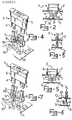
- a fuse carrier according to the invention which comprises a plurality of sockets 2 for fuses 3 of the so-called reed type.
- Each reed fuse 3 is comprises conventionally a pair of parallel reeds 4 and 5 between which a fuse filament, not shown, is secured transversely; the reeds and filament are accommodated within a body 6 of a clear plastics synthetic material.
- Each fuse 3 is supported in its respective socket 2 by a pair of clip electrodes 7 and 8 which are adapted to clinch on the fuse reeds 4 and 5, respectively.
- the clip electrodes 7 and 8 also form the electric connection for the fuse 3, and for this purpose, they are provided with pin terminals, indicated at 9, which are soldered to suitable electric connection paths 10 formed on a printed circuit 11 housed within the fuse carrier 1.
- each fuse 3 would conventionally connect to a corresponding power supply circuit for an electrical apparatus of the vehicle to be protected against shorting.
- a lamp 12 is held between the clip electrodes 7 and 8, in axial alignment to the fuse 3. More specifically, the lamp 12 is a microlamp having a glass base and rheophores, 13 and 14, for connection to the filament.
- the lamp 12 is supported between the clips 7 and 8 with its base fitted into a sleeve lampholder 15, which comprises a pair of half-rings 16 and 17 structurally independent of each other and being each attached to and supported by a corresponding arm 18 and 19 extending perpendicularly to the clip electrodes 7 and 8.
- the clip electrodes 7 and 8, and corresponding arms 18 and 19 laid to support the half-rings 16 and 17 of the sleeve 15 define a lampholder for the microlamp 12, while also powering the rheophores 13 and 14 thereof.
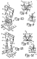
- a second embodiment provides for the supporting arms, indicated at 20 and 21, of the sleeve 15 to be bent at right angles such that the sleeve 15 can be offset from the fuse 3.
- the lamp 12 is carried laterally of the fuse 3 at a location underlying a window 22 imprinted with an ideogram 23 related generally to the kind of electrical apparatus being protected by that fuse.
- the free lead rheophores 13 and 14 of the lamp 12 are soldered directly to the supporting arms 18 and 19 of the sleeve 15; and in a further embodiment, the rheophores 13 and 14 of a microlamp 12 are soldered directly to the paths 10 of the printed circuit 11.
- the microlamp 12 would be secured to the paths 10 of the printed circuit 11 at a location underlying the window 22 which carries the ideogram 23 related to the circuit and electrical apparatus wherein the corresponding fuse is connected.
- an exemplary embodiment thereof may include a plurality of lamps or light emitting diodes (LED) secured on the printed circuit 11 and being each parallel connected to a respective fuse such that the lamps, on the one side, and the fuses, on the other side, will correspond with one another by their number and order.
- LED light emitting diodes
- the fuse carrier of this invention affords the important advantage that, by virtue of the lamp being supported by and powered through the clip electrodes carrying the fuse, the lamp is structurally and operatively independent of the latter. Thus, in a burned out fuse filament situation, such as due to shorting, where the fuse is to be replaced, the indicator lamp will be turned on and facilitate its location.
- the lamp is positioned in the fuse carrier to illuminate the ideogram associated with a fuse
- the electrical apparatus affected by the short is also more easily located.
- the cost of the fuse carrier according to the invention is comparable to that of conventional fuse carriers, and enables replacement of a burned out fuse while retaining its lamp.
- the fuse carrier of this invention is apt to upgrade a vehicle equipped with it.
Landscapes
- Fuses (AREA)
Applications Claiming Priority (2)
| Application Number | Priority Date | Filing Date | Title |
|---|---|---|---|
| IT2235686 | 1986-11-17 | ||
| IT22356/86A IT1198097B (it) | 1986-11-17 | 1986-11-17 | Scatola porta fusibili particolarmente per veicoli |
Publications (2)
| Publication Number | Publication Date |
|---|---|
| EP0268563A2 true EP0268563A2 (de) | 1988-05-25 |
| EP0268563A3 EP0268563A3 (de) | 1990-01-24 |
Family
ID=11195150
Family Applications (1)
| Application Number | Title | Priority Date | Filing Date |
|---|---|---|---|
| EP87830196A Withdrawn EP0268563A3 (de) | 1986-11-17 | 1987-05-26 | Ein Sicherungshalter, insbesondere für Fahrzeuge |
Country Status (3)
| Country | Link |
|---|---|
| US (1) | US4815993A (de) |
| EP (1) | EP0268563A3 (de) |
| IT (1) | IT1198097B (de) |
Cited By (1)
| Publication number | Priority date | Publication date | Assignee | Title |
|---|---|---|---|---|
| GB2323981A (en) * | 1997-04-01 | 1998-10-07 | Care Slade Wayne Paul | Indicator lamp and electric fuse |
Families Citing this family (14)
| Publication number | Priority date | Publication date | Assignee | Title |
|---|---|---|---|---|
| US5153523A (en) * | 1990-11-23 | 1992-10-06 | Joseph Samaniego | Selective fused circuit continuity test apparatus |
| USRE36317E (en) * | 1994-12-30 | 1999-09-28 | Arratia; Jose F. | Indicating fuse block |
| US5659283A (en) * | 1994-12-30 | 1997-08-19 | Arratia; Jose F. | Indicating fuse block |
| US5701118A (en) * | 1996-02-20 | 1997-12-23 | Hull; Harold L. | Blown fuse indicator circuit and fuse cap, including a method of use therefore |
| USD394843S (en) | 1996-07-17 | 1998-06-02 | Pacific Engineering Co., Ltd. | Fuse holder for automobiles |
| US5876239A (en) * | 1996-08-30 | 1999-03-02 | The Whitaker Corporation | Electrical connector having a light indicator |
| US6168471B1 (en) | 1998-04-03 | 2001-01-02 | Cathy D. Santa Cruz | Ferrule-to-blade fuse adapter with a blown fuse indicator |
| TW412054U (en) * | 1999-03-18 | 2000-11-11 | Lin Chuen Ru | Car use fuse device with malfunction displaying light |
| TW534450U (en) * | 2002-06-03 | 2003-05-21 | Chuen-Ru Lin | Fuse for breakdown indicator of automobile facilities |
| US7710236B2 (en) * | 2006-08-01 | 2010-05-04 | Delphi Technologies, Inc. | Fuse systems with serviceable connections |
| US7839258B2 (en) * | 2008-08-06 | 2010-11-23 | Wen-Tsung Cheng | Fuse assembly with a capability of indicating a fusing state by light |
| US8169291B2 (en) * | 2010-01-06 | 2012-05-01 | Wen-Tsung Cheng | Combination-type fuse |
| US8164411B2 (en) * | 2010-01-06 | 2012-04-24 | Wen-Tsung Cheng | Fuse structure with power disconnection light indicating function |
| US12340966B2 (en) * | 2022-05-25 | 2025-06-24 | Astec International Limited | Fuse holder |
Family Cites Families (13)
| Publication number | Priority date | Publication date | Assignee | Title |
|---|---|---|---|---|
| US852539A (en) * | 1906-12-17 | 1907-05-07 | Leonard B Buchanan | Indicating device for electric fuses or cut-outs. |
| US1641203A (en) * | 1926-03-03 | 1927-09-06 | Scordamaglia Frank | Electric-fuse indicator |
| US1902804A (en) * | 1932-03-03 | 1933-03-21 | Great Western Fuse Company | Fuse clip lock |
| US2128418A (en) * | 1936-07-16 | 1938-08-30 | Mar Frank C La | Indicator |
| US2321271A (en) * | 1942-05-13 | 1943-06-08 | Utility Electric Corp | Fuse holder |
| BE495498A (de) * | 1949-05-07 | |||
| ES333011A1 (es) * | 1966-04-12 | 1967-07-16 | Bassani Spa | Portafusible enchufable en condiciones de maxima seguridad. |
| US3739313A (en) * | 1971-02-19 | 1973-06-12 | Mc Graw Edison Co | Protectors for electric circuits |
| US4238140A (en) * | 1979-03-01 | 1980-12-09 | Ford Motor Company | Terminal block with electrical connection means with connector location wall and locking finger |
| US4499447A (en) * | 1983-06-17 | 1985-02-12 | Guim Multi-Tech Corporation | Blade terminal fuses with integrity indicator |
| US4556274A (en) * | 1983-12-21 | 1985-12-03 | Motorola, Inc. | Fuse and mounting arrangement for printed circuit board application |
| US4695815A (en) * | 1985-05-07 | 1987-09-22 | Chern Hwang | Automobile fuse with damage indicator |
| US4695107A (en) * | 1986-06-09 | 1987-09-22 | Leppert James B | Integrated circuit sockets |
-
1986
- 1986-11-17 IT IT22356/86A patent/IT1198097B/it active
-
1987
- 1987-05-26 EP EP87830196A patent/EP0268563A3/de not_active Withdrawn
- 1987-08-19 US US07/087,178 patent/US4815993A/en not_active Expired - Fee Related
Cited By (1)
| Publication number | Priority date | Publication date | Assignee | Title |
|---|---|---|---|---|
| GB2323981A (en) * | 1997-04-01 | 1998-10-07 | Care Slade Wayne Paul | Indicator lamp and electric fuse |
Also Published As
| Publication number | Publication date |
|---|---|
| IT8622356A1 (it) | 1988-05-17 |
| US4815993A (en) | 1989-03-28 |
| IT1198097B (it) | 1988-12-21 |
| EP0268563A3 (de) | 1990-01-24 |
| IT8622356A0 (it) | 1986-11-17 |
Similar Documents
| Publication | Publication Date | Title |
|---|---|---|
| US4815993A (en) | Fuse carrier particularly for vehicles | |
| EP1217291B1 (de) | Leuchten | |
| EP0271449A1 (de) | Zwischensockel für Stecksicherung | |
| US5789911A (en) | Polarity testing probe and LED cartridge assembly | |
| US5690509A (en) | Lighted accessory power supply cord | |
| US6490992B2 (en) | Pointer instrument | |
| US3864001A (en) | Lamp socket | |
| US4084873A (en) | Lamp and holder combination with adapter | |
| ATE359611T1 (de) | Rotorlose fassung für leuchtstofflampen | |
| HU9904394D0 (en) | Electric lamp | |
| JP4716698B2 (ja) | シガーライタまたは多機能電気ソケットの照明装置 | |
| US4178627A (en) | Lamp assembly | |
| US3761703A (en) | Apparatus for illumination of instrument faces | |
| HK91593A (en) | Adapter for a single-base low-pressure discharge lamp | |
| US3471829A (en) | Multiple flashing light unit | |
| JP2003068130A (ja) | 照明器具 | |
| EP0976617A1 (de) | Stützkörper für Beleuchtungslampen von Kraftfahrzeugkennzeichen-Schildern | |
| US20040264205A1 (en) | Modular light assembly and method for installing a modular light assembly in a vehicle | |
| GB2079436A (en) | Electric lamp and a bulb for use therein | |
| AU747071B2 (en) | Carrier, primarily for light emitting diode | |
| ITTO20000150U1 (it) | Proiettore. | |
| US20040140750A1 (en) | Lamp base, and a lamp having a lamp base | |
| GB2294806A (en) | A filament lamp | |
| RU13891U1 (ru) | Устройство излучения бокового сигнального фонаря транспортного средства | |
| GB2216738A (en) | Lamp having bulbholder; replacing sealed beam unit |
Legal Events
| Date | Code | Title | Description |
|---|---|---|---|
| PUAI | Public reference made under article 153(3) epc to a published international application that has entered the european phase |
Free format text: ORIGINAL CODE: 0009012 |
|
| AK | Designated contracting states |
Kind code of ref document: A2 Designated state(s): AT BE CH DE ES FR GB GR LI LU NL SE |
|
| PUAL | Search report despatched |
Free format text: ORIGINAL CODE: 0009013 |
|
| AK | Designated contracting states |
Kind code of ref document: A3 Designated state(s): AT BE CH DE ES FR GB GR LI LU NL SE |
|
| 17P | Request for examination filed |
Effective date: 19900521 |
|
| STAA | Information on the status of an ep patent application or granted ep patent |
Free format text: STATUS: THE APPLICATION IS DEEMED TO BE WITHDRAWN |
|
| 18D | Application deemed to be withdrawn |
Effective date: 19901201 |
|
| RIN1 | Information on inventor provided before grant (corrected) |
Inventor name: FALCHETTI, UMBERTO |