EP0268566A2 - Dispositif d'émission par la base - Google Patents
Dispositif d'émission par la base Download PDFInfo
- Publication number
- EP0268566A2 EP0268566A2 EP87850268A EP87850268A EP0268566A2 EP 0268566 A2 EP0268566 A2 EP 0268566A2 EP 87850268 A EP87850268 A EP 87850268A EP 87850268 A EP87850268 A EP 87850268A EP 0268566 A2 EP0268566 A2 EP 0268566A2
- Authority
- EP
- European Patent Office
- Prior art keywords
- housing
- projectile body
- igniter
- restricting wall
- base bleed
- Prior art date
- Legal status (The legal status is an assumption and is not a legal conclusion. Google has not performed a legal analysis and makes no representation as to the accuracy of the status listed.)
- Withdrawn
Links
- 239000000446 fuel Substances 0.000 claims abstract description 27
- 238000002485 combustion reaction Methods 0.000 claims abstract description 15
- 230000002093 peripheral effect Effects 0.000 claims abstract description 4
- 238000000034 method Methods 0.000 claims description 5
- 238000004026 adhesive bonding Methods 0.000 claims description 2
- 239000000567 combustion gas Substances 0.000 abstract 1
- 230000001133 acceleration Effects 0.000 description 3
- 239000004429 Calibre Substances 0.000 description 2
- 230000002349 favourable effect Effects 0.000 description 2
- 239000007789 gas Substances 0.000 description 2
- 238000003754 machining Methods 0.000 description 2
- 238000004519 manufacturing process Methods 0.000 description 2
- 239000000654 additive Substances 0.000 description 1
- 238000005336 cracking Methods 0.000 description 1
- 239000006185 dispersion Substances 0.000 description 1
- 239000002360 explosive Substances 0.000 description 1
- 239000003721 gunpowder Substances 0.000 description 1
- 239000002184 metal Substances 0.000 description 1
- 230000004048 modification Effects 0.000 description 1
- 238000012986 modification Methods 0.000 description 1
- 230000000704 physical effect Effects 0.000 description 1
- 239000004033 plastic Substances 0.000 description 1
- 229920003023 plastic Polymers 0.000 description 1
- 230000001681 protective effect Effects 0.000 description 1
Images

Classifications
-
- F—MECHANICAL ENGINEERING; LIGHTING; HEATING; WEAPONS; BLASTING
- F42—AMMUNITION; BLASTING
- F42B—EXPLOSIVE CHARGES, e.g. FOR BLASTING, FIREWORKS, AMMUNITION
- F42B10/00—Means for influencing, e.g. improving, the aerodynamic properties of projectiles or missiles; Arrangements on projectiles or missiles for stabilising, steering, range-reducing, range-increasing or fall-retarding
- F42B10/32—Range-reducing or range-increasing arrangements; Fall-retarding means
- F42B10/38—Range-increasing arrangements
- F42B10/40—Range-increasing arrangements with combustion of a slow-burning charge, e.g. fumers, base-bleed projectiles
Definitions
- the present invention relates to a base bleed unit, arranged to increase the range of fire or decrease the time of flight for shells and projectiles.
- a pyrotechnical charge of non-pressure sensitive type is used, known as an igniter.
- An example of a base bleed unit having such an igniter is disclosed in SE, A, 340 076.
- Other solutions to the reignition problem are also known, e.g. as disclosed in GB, A, 2 131 926 and DE, A1, 246 380, but these are mechanically complicated.
- the object of the present invention is to disclose a base bleed unit comprising a single and easily replaceable unit, which, when demounted, does not leave any structural elements remaining by the shell body.
- the shell body does not require machining in order to facilitate attachment of the igniter, and the igniter does thus not require attachment to the shell.
- the igniter is of an extremely efficient type, having an advantageous location facilitating maximum security for reignition, and smaller and less expensive igniter charges can also be used.
- the outlet nozzle from the base bleed unit is advantageously in the form of a multi-hole nozzle arrangement with the position of the nozzles arranged to facilitate use of fuel charges having heavy components or additives. The nozzles also improve the efficiency of the unit, i.e. the base drag reducing function of same.
- the base bleed unit according to the present invention is with regard to manufacture, handling and function considerably improved in relation to previously utilized solutions, and also well adapted for use in combination with ammunition having small calibre, e.g. 30, 40 and 57 mm.
- the base bleed unit includes a member attachable by the rear portion of a projectile body, arranged to form a housing in combination with said rear portion surrounding at least one fuel charge and at least one igniter comprising a pyrotechnical charge, and including at least one outlet nozzle by the portion of the housing directed away from the projectile body, said fuel charge being arranged during combustion to generate a mass flow intended to reduce existing base drag, and it is mainly characterised in that igniter or igniters included in the unit are located adjacent to the internal surface of the restricting wall in the housing which is located at a distance from the rear surface of the projectile body.
- the housing 1 has a rear wall located at a distance from the rear plane of the projectile body 2, and said wall includes a centrally located and outwardly extending part 3, in which an igniter 4 is located in a blind hole, open in direction towards the rear plane of the projectile body 2.
- the rear wall also includes a number of outlet nozzles 5, 5 ⁇ , 5 ⁇ , located spaced from each other in an annular and surrounding relationship to the igniter 4.
- a fuel charge 6 is also arranged within the housing 1, and comprising two semi-circular parts in the shown embodiment.
- outlet nozzles, 5, 5 ⁇ , 5 ⁇ are advantageously arranged extending in an inclined relationship to the length axis of the projectile body 2, and with the outer portions located more adjacent to the peripheral part of the housing 1 than the inlets, but the outlet nozzles, 5, 5 ⁇ , 5 ⁇ can also be arranged extending in a substantially parallel relationship to the length axis of the projectile body 2.
- the pyrotechnical charge forming an igniter 4 is ignited, as well as the fuel charge 6, by the combustion flame from the drive charge, which penetrates through the outlet nozzles 5, 5 ⁇ , 5 ⁇ . Since the igniter 4 is open in direction towards the rear plane of the projectile body 2, the flame from the igniter 4 is directed towards the fuel charge 6, and away from the outlet nozzles 5, 5 ⁇ , 5 ⁇ .
- the combustion of the fuel charge 6 is hereby also maintained during the pressure drop occuring when leaving the muzzle of the gun, and in difference to the igniters which previously have been located adjacent to the rear plane of the projectile body 2, having a combustion flame with a substantial part directed out through the outlet nozzle, a considerably improved reignition function is achieved, which results in that combustion of the fuel charge 6 is maintained substantially unchanged also during the pressure drop occuring when leaving the muzzle of the gun.
- the efficient use of the igniter 4 thus facilitates use of a smaller charge with maintained or improved security.
- the outwardly inclined outlet nozzles 5, 5 ⁇ , 5 ⁇ makes it possible to obtain a total outlet area of considerable size, but also improved gas flow characteristics adjacent to the base plane, resulting in a further reduction of the base drag in relation to what is accomplished with a base bleed unit having a centrally located outlet nozzle.
- a base bleed unit can thus be easily replaced by, for example, a projectile extension, and it can easily be removed and remounted in connection with revision of the base bleed unit, i.e. when replacing the igniter 4 and the fuel charge 6 of the unit.
- revision is further simplified by the fact that the housing 1, when demounted, facilitates free access to both the fuel charge 6 and the igniter 4 from the end portion which is intended to be attached against a projectile body 2.
- Figs. 3 and 4 show an example of a second embodiment of a replaceable unit according to the invention, with the rear wall portion of the housing 1 having such a thickness, that no outwardly extending part 3 is required to facilitate attachment of the igniter 4.
- such an outwardly extending part 3 is less desirable, and it may thus be avoided by increasing the rear wall thickness of the housing 1. It is also shown in this embodiment, how an existing recess in the rear plane of the projectile body 2 can be used to surround part of the fuel charge 6, and how the total length extension of the housing 1 thereby can be reduced.
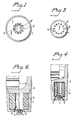
- FIGs. 5 and 6 show an example of such an embodiment, in which the centrally located outlet nozzle 7 by the portion directed towards the fuel charge 6 is arranged with an annular groove, in which an annular igniter 4 is located.
- FIG. 7 A further alternative embodiment having a centrally located outlet nozzle 7 is shown in Fig. 7, in which the centrally located igniter 4 of the previous embodiment is replaced by a number of igniters 4, 4 ⁇ , for example four individual ones, located spaced from each other in blind holes taken from the inside plane of the rear wall of the housing 1.
- the surface of the pyrotechnical charge of each igniter 4, 4 ⁇ , which is directed towards the fuel charge 6, can advantageously be arranged partly covered, which in this embodiment is illustrated by a washer-shaped member 8, having a hole diameter causing at least the outer part of each igniter 4, 4 ⁇ being covered.
- each igniter 4, 4 ⁇ results in that the combustion flame is "directed" towards the opposed surface of the fuel charge 6, but also improves the support for the fuel charge 6 against the acceleration forces applied during launch. It is also possible to use other methods to make the part of the igniter 4, 4 ⁇ directed towards the fuel charge 6 to become partly covered, e.g. by locating the pyrotechnical charge constituting an igniter 4, 4 ⁇ in a surrounding tubular member 9, which includes a partly covered lidshaped member 10 by one end portion, and an example of such a surrounding tubular member 9 is shown in Fig. 8.
- a rearwardly open projectile extension is used, known as a skirt, and such an extension may comprise of a member integrated with the projectile body 2, but may also be a tubular member 11 attached to the projectile body 2, e.g. attached by means of a screw thread.
- This type of projectiles can advantageously be used with a base bleed unit according to the present invention, which to some extent is indicated in Fig. 4, but which is further emphasized by the embodiment shown in Fig. 9.
- the projectile body 2 is arranged with a rearwardly open projectile extension 11, which by the internal free edge portion is arranged with a screw thread, against which a bottom member 12 is attached, in which igniters 4, 4 ⁇ having surrounding tubular members according to Fig.
- the bleed unit thus comprises only of the bottom member 12 and therein arranged igniters 4, 4 ⁇ , and the fuel charge 6, while a surrounding housing for the fuel charge 6 is accomplished by using the projectile body 2 with associated projectile extension 11.
- the fuel charge 6 with associated bottom member 12, and therein arranged igniters 4, 4 ⁇ are advantageously arranged protected and joined into one unit by means of a protective cover 13 surrounding the fuel charge 6, e.g. of metal or synthetic plastics, attached to the bottom member 12, and such a unit can be handled as an easily replaceable unit, which can be easily stored, transported and mounted or demounted.
- Each igniter 4, 4 ⁇ includes advantageously a surrounding tubular member, preferably open at both end portions.
- a suitable pyrotechnical charge it can be attached to intended blind hole by means of a gluing method, or by choosing the tolerance between the outer diameter of the tubular member and the diameter of the blind hole in such a fashion, that a press fit is accomplished therebetween.
- the igniter charge may also be pressed directly into intended space by the rear wall of the housing 1.
- a multi-hole outlet nozzle arrangement is preferred, but also other arrangements may be used.
- a multi-hole outlet nozzle arrangement it is preferred to arrange the outlet nozzles 5, 5 ⁇ , 5 ⁇ with an inclined extension, as shown in Figs. 2 and 4, but also outlet nozzles having a substantially perpendicular line of extension in relation to the base plane of the housing 1 can be used.
- the present invention thus results in substantial advantages in relation to previously known types of base bleed units, and facilitates simple modification of existing shells and projectiles for use in combination with a base bleed unit. Furthermore, it is also considerably easier to accomplish base bleed for ammunition having small calibre, e.g. 30, 40 and 57 mm.
- a multi-hole outlet nozzle arrangement may thus include a substantially centrally located outlet nozzle 7, surrounded by from each other spaced outlet nozzles 5, 5 ⁇ , 5 ⁇ .
Landscapes
- Physics & Mathematics (AREA)
- Fluid Mechanics (AREA)
- Engineering & Computer Science (AREA)
- General Engineering & Computer Science (AREA)
- Aiming, Guidance, Guns With A Light Source, Armor, Camouflage, And Targets (AREA)
- Air Bags (AREA)
- Lighters Containing Fuel (AREA)
Applications Claiming Priority (2)
| Application Number | Priority Date | Filing Date | Title |
|---|---|---|---|
| SE8603737 | 1986-09-05 | ||
| SE8603737A SE460872B (sv) | 1986-09-05 | 1986-09-05 | Basfloedesaggregatet foer granater och projektiler |
Publications (2)
| Publication Number | Publication Date |
|---|---|
| EP0268566A2 true EP0268566A2 (fr) | 1988-05-25 |
| EP0268566A3 EP0268566A3 (fr) | 1990-08-08 |
Family
ID=20365503
Family Applications (1)
| Application Number | Title | Priority Date | Filing Date |
|---|---|---|---|
| EP87850268A Withdrawn EP0268566A3 (fr) | 1986-09-05 | 1987-09-03 | Dispositif d'émission par la base |
Country Status (5)
| Country | Link |
|---|---|
| US (1) | US4807532A (fr) |
| EP (1) | EP0268566A3 (fr) |
| IL (1) | IL83743A0 (fr) |
| IN (1) | IN168398B (fr) |
| SE (1) | SE460872B (fr) |
Cited By (1)
| Publication number | Priority date | Publication date | Assignee | Title |
|---|---|---|---|---|
| GB2622383A (en) * | 2022-09-14 | 2024-03-20 | Bae Systems Plc | Improved range extension device |
Families Citing this family (18)
| Publication number | Priority date | Publication date | Assignee | Title |
|---|---|---|---|---|
| GB9216295D0 (en) * | 1992-07-31 | 1998-05-06 | Secr Defence | Long range artillery range |
| IL107763A0 (en) * | 1993-11-26 | 1994-02-27 | State Of Isreal Ministery Of D | Infrared microscope |
| SE508403C2 (sv) * | 1996-12-15 | 1998-10-05 | Gunners Nils Erik | Basflödesaggregat |
| DE19751932C2 (de) * | 1997-11-22 | 2001-04-19 | Rheinmetall W & M Gmbh | Gasgenerator zur Reichweitensteigerung eines Geschosses und Geschoß mit Gasgenerator |
| US6727485B2 (en) * | 2001-05-25 | 2004-04-27 | Omnitek Partners Llc | Methods and apparatus for increasing aerodynamic performance of projectiles |
| US7150232B1 (en) | 2001-05-25 | 2006-12-19 | Omnitek Partners Llc | Methods and apparatus for increasing aerodynamic performance of projectiles |
| AUPS303702A0 (en) * | 2002-06-20 | 2002-07-11 | Metal Storm Limited | A cartridge assembly for multiple projectiles |
| AU2003900572A0 (en) * | 2003-02-10 | 2003-02-20 | Metal Storm Limited | Electronically selectable kinetic energy projectile |
| US7578238B1 (en) * | 2006-01-12 | 2009-08-25 | The United States Of America As Represented By The Secretary Of The Army | Base bleed boat tail converter for projectile |
| US7802520B2 (en) * | 2007-07-25 | 2010-09-28 | Martin Electronics | Drag minimizing projectile delivery system |
| US7823510B1 (en) | 2008-05-14 | 2010-11-02 | Pratt & Whitney Rocketdyne, Inc. | Extended range projectile |
| US7891298B2 (en) * | 2008-05-14 | 2011-02-22 | Pratt & Whitney Rocketdyne, Inc. | Guided projectile |
| US20110061556A1 (en) * | 2009-09-15 | 2011-03-17 | Raytheon Company | Methods and apparatus for a gas outlet port clog inhibitor |
| RU2462686C2 (ru) * | 2010-12-24 | 2012-09-27 | Федеральное государственное бюджетное образовательное учреждение высшего профессионального образования "Ижевский государственный технический университет имени М.Т. Калашникова" | Способ увеличения дальности полета снаряда (варианты) и устройство для его реализации |
| US8671839B2 (en) * | 2011-11-04 | 2014-03-18 | Joseph M. Bunczk | Projectile and munition including projectile |
| RU2647715C1 (ru) * | 2017-04-06 | 2018-03-19 | Акционерное общество "Концерн "Калашников" | Способ увеличения дальности полета снаряда и устройство для его реализации (варианты) |
| US11156442B1 (en) | 2018-10-11 | 2021-10-26 | U.S. Government As Represented By The Secretary Of The Army | Dynamic instability reduced range round |
| GB2622382A (en) * | 2022-09-14 | 2024-03-20 | Bae Systems Plc | Range extension device |
Family Cites Families (9)
| Publication number | Priority date | Publication date | Assignee | Title |
|---|---|---|---|---|
| US3143853A (en) * | 1961-12-28 | 1964-08-11 | Gen Motors Corp | Solid propellant burn area control |
| GB1138192A (en) * | 1965-01-18 | 1968-12-27 | Pains Wessex Ltd | Improvements in and relating to pyrotechnic devices |
| US4213393A (en) * | 1977-07-15 | 1980-07-22 | Gunners Nils Erik | Gun projectile arranged with a base drag reducing system |
| US4397240A (en) * | 1977-12-06 | 1983-08-09 | Aai Corporation | Rocket assisted projectile and cartridge with time delay ignition and sealing arrangement |
| SE442246B (sv) * | 1980-10-28 | 1985-12-09 | Bofors Ab | Sett och anordning att minska basmotstandet for projektiler |
| DE3246380A1 (de) * | 1982-12-15 | 1984-06-20 | Diehl GmbH & Co, 8500 Nürnberg | Vorrichtung zur reduzierung des bodenwiderstandes bei geschossen |
| DE3437250A1 (de) * | 1984-10-11 | 1986-04-17 | Rheinmetall GmbH, 4000 Düsseldorf | Treibsatz zur bodensogreduzierung fuer ein artilleriegeschoss |
| DE3510446A1 (de) * | 1985-03-22 | 1986-09-25 | Nico-Pyrotechnik Hanns-Jürgen Diederichs GmbH & Co KG, 2077 Trittau | Treibsatz zur bodensogreduzierung |
| FR2583157B1 (fr) * | 1985-06-06 | 1987-11-20 | Poudres & Explosifs Ste Nale | Allumeur destine aux chargements generateurs de gaz des obus |
-
1986
- 1986-09-05 SE SE8603737A patent/SE460872B/sv not_active IP Right Cessation
-
1987
- 1987-09-02 US US07/096,631 patent/US4807532A/en not_active Expired - Fee Related
- 1987-09-02 IN IN775/DEL/87A patent/IN168398B/en unknown
- 1987-09-02 IL IL83743A patent/IL83743A0/xx unknown
- 1987-09-03 EP EP87850268A patent/EP0268566A3/fr not_active Withdrawn
Cited By (1)
| Publication number | Priority date | Publication date | Assignee | Title |
|---|---|---|---|---|
| GB2622383A (en) * | 2022-09-14 | 2024-03-20 | Bae Systems Plc | Improved range extension device |
Also Published As
| Publication number | Publication date |
|---|---|
| US4807532A (en) | 1989-02-28 |
| EP0268566A3 (fr) | 1990-08-08 |
| SE460872B (sv) | 1989-11-27 |
| IN168398B (fr) | 1991-03-23 |
| IL83743A0 (en) | 1988-02-29 |
| SE8603737D0 (sv) | 1986-09-05 |
| SE8603737L (sv) | 1988-03-06 |
Similar Documents
| Publication | Publication Date | Title |
|---|---|---|
| EP0268566A2 (fr) | Dispositif d'émission par la base | |
| US10677574B2 (en) | Self contained internal chamber for a projectile | |
| CA2543729A1 (fr) | Cartouche | |
| US4754704A (en) | Propellant charge for the reduction of base eddying | |
| US5481978A (en) | Cartridge case | |
| US4163335A (en) | Black powder firing nipple | |
| US8464639B2 (en) | Shaped charge fuse booster system for dial lethality in reduced collateral damage bombs (RCDB) | |
| US6889611B2 (en) | Smoke shell | |
| US6971299B2 (en) | Countermass weapon | |
| US5610365A (en) | Cartridge ammunition having a case, an arrow projectile and an igniter-coated propellant | |
| EP0943074B1 (fr) | Unite reductrice de trainee de culot | |
| EP0461095A1 (fr) | Améliorations relatives aux amorces pour charges propulsives | |
| US5589658A (en) | Sabot with controlled separation of the elements for subcaliber projectiles | |
| RU2150074C1 (ru) | Патрон с реактивной пулей (варианты) | |
| US1353118A (en) | Cartridge | |
| RU2462686C2 (ru) | Способ увеличения дальности полета снаряда (варианты) и устройство для его реализации | |
| US4721042A (en) | Missiles with annular flare | |
| US7360355B1 (en) | Long range artillery shell | |
| JP2514150Y2 (ja) | 減口径弾用装弾筒 | |
| US8453574B2 (en) | MCD shell | |
| RU2125229C1 (ru) | Реактивный артиллерийский снаряд | |
| DE10034345B4 (de) | Aus einer Rohrwaffe verschießbares Vollkalibergeschoß | |
| JP2943077B2 (ja) | 翼安定弾のオブチュレータ | |
| RU2422757C1 (ru) | Артиллерийский малокалиберный патрон | |
| GB2089009A (en) | Blast Equalizer for a Gun fired Ramjet Projectile |
Legal Events
| Date | Code | Title | Description |
|---|---|---|---|
| PUAI | Public reference made under article 153(3) epc to a published international application that has entered the european phase |
Free format text: ORIGINAL CODE: 0009012 |
|
| AK | Designated contracting states |
Kind code of ref document: A2 Designated state(s): AT BE DE ES FR GB GR IT NL |
|
| PUAL | Search report despatched |
Free format text: ORIGINAL CODE: 0009013 |
|
| AK | Designated contracting states |
Kind code of ref document: A3 Designated state(s): AT BE DE ES FR GB GR IT NL |
|
| 17P | Request for examination filed |
Effective date: 19910205 |
|
| STAA | Information on the status of an ep patent application or granted ep patent |
Free format text: STATUS: THE APPLICATION IS DEEMED TO BE WITHDRAWN |
|
| 18D | Application deemed to be withdrawn |
Effective date: 19920331 |