EP0268633B1 - Erzeugung eines ultraschallfeldes - Google Patents
Erzeugung eines ultraschallfeldes Download PDFInfo
- Publication number
- EP0268633B1 EP0268633B1 EP19870903377 EP87903377A EP0268633B1 EP 0268633 B1 EP0268633 B1 EP 0268633B1 EP 19870903377 EP19870903377 EP 19870903377 EP 87903377 A EP87903377 A EP 87903377A EP 0268633 B1 EP0268633 B1 EP 0268633B1
- Authority
- EP
- European Patent Office
- Prior art keywords
- acoustic
- source
- standing wave
- container
- convergence
- Prior art date
- Legal status (The legal status is an assumption and is not a legal conclusion. Google has not performed a legal analysis and makes no representation as to the accuracy of the status listed.)
- Expired
Links
- 239000012530 fluid Substances 0.000 claims description 23
- 238000000034 method Methods 0.000 claims description 8
- 230000005540 biological transmission Effects 0.000 claims description 7
- 230000003993 interaction Effects 0.000 claims 1
- 230000000694 effects Effects 0.000 abstract description 7
- 239000007788 liquid Substances 0.000 abstract description 7
- 238000002604 ultrasonography Methods 0.000 abstract description 7
- 239000002245 particle Substances 0.000 description 17
- 230000005855 radiation Effects 0.000 description 7
- XLYOFNOQVPJJNP-UHFFFAOYSA-N water Substances O XLYOFNOQVPJJNP-UHFFFAOYSA-N 0.000 description 7
- 238000000926 separation method Methods 0.000 description 3
- 230000004907 flux Effects 0.000 description 2
- 230000000644 propagated effect Effects 0.000 description 2
- VVQNEPGJFQJSBK-UHFFFAOYSA-N Methyl methacrylate Chemical compound COC(=O)C(C)=C VVQNEPGJFQJSBK-UHFFFAOYSA-N 0.000 description 1
- 239000004793 Polystyrene Substances 0.000 description 1
- 238000003491 array Methods 0.000 description 1
- 230000004323 axial length Effects 0.000 description 1
- JRPBQTZRNDNNOP-UHFFFAOYSA-N barium titanate Chemical compound [Ba+2].[Ba+2].[O-][Ti]([O-])([O-])[O-] JRPBQTZRNDNNOP-UHFFFAOYSA-N 0.000 description 1
- 229910002113 barium titanate Inorganic materials 0.000 description 1
- 239000000919 ceramic Substances 0.000 description 1
- 239000013078 crystal Substances 0.000 description 1
- 238000005516 engineering process Methods 0.000 description 1
- 238000002474 experimental method Methods 0.000 description 1
- 239000006194 liquid suspension Substances 0.000 description 1
- 239000000463 material Substances 0.000 description 1
- 239000000203 mixture Substances 0.000 description 1
- 238000009659 non-destructive testing Methods 0.000 description 1
- 239000013618 particulate matter Substances 0.000 description 1
- 229920002223 polystyrene Polymers 0.000 description 1
- 239000012286 potassium permanganate Substances 0.000 description 1
- 230000000750 progressive effect Effects 0.000 description 1
- 238000005204 segregation Methods 0.000 description 1
- 239000000126 substance Substances 0.000 description 1
Images
Classifications
-
- G—PHYSICS
- G10—MUSICAL INSTRUMENTS; ACOUSTICS
- G10K—SOUND-PRODUCING DEVICES; METHODS OR DEVICES FOR PROTECTING AGAINST, OR FOR DAMPING, NOISE OR OTHER ACOUSTIC WAVES IN GENERAL; ACOUSTICS NOT OTHERWISE PROVIDED FOR
- G10K15/00—Acoustics not otherwise provided for
-
- G—PHYSICS
- G10—MUSICAL INSTRUMENTS; ACOUSTICS
- G10K—SOUND-PRODUCING DEVICES; METHODS OR DEVICES FOR PROTECTING AGAINST, OR FOR DAMPING, NOISE OR OTHER ACOUSTIC WAVES IN GENERAL; ACOUSTICS NOT OTHERWISE PROVIDED FOR
- G10K11/00—Methods or devices for transmitting, conducting or directing sound in general; Methods or devices for protecting against, or for damping, noise or other acoustic waves in general
- G10K11/18—Methods or devices for transmitting, conducting or directing sound
- G10K11/26—Sound-focusing or directing, e.g. scanning
Definitions
- This invention relates to the generation of ultrasonic fields. It is particularly, but not necessarily exclusively, concerned with the generation of such fields for use in the manipulation of particulate matter in a fluid medium, including the removal of particles from a liquid suspension and the segregation of dissimilar particles from a mixture of particles.
- Acoustic energy sources have been used to generate progressive and standing waves for a variety of purposes.
- ultrasonic energy can have an influence on the behaviour of particles suspended in fluids, it being known that particles can be attracted to the nodes of a standing ultrasonic wave. In essence, the attracted particles become concentrated in planes lying normal to the axis of propagation of the standing wave. If the wave is moved along the axis of propagation, the particles can then be carried through the fluid while they remain attached to the standing wave.
- acoustic streaming When energy is propagated from an ultrasound source through a fluid, the energy level at any point in the fluid will decrease with increasing distance from the source because of attenuation by the fluid. Divergence of the beam accentuates this effect.
- the acoustic energy propagated by that source is therefore subject to an energy density gradient which is experienced by the fluid as a uni-directional force, in effect a radiation pressure. Such a force can cause the fluid to move away from the radiation source, this movement being referred to herein as acoustic streaming.
- acoustic energy is to be used to control the movement of particles in a volume of fluid, it is more usually the case that a standing wave is employed. Should the standing wave be formed by a normal reflection of ultrasound radiation from a single source, as in the example of U.S. 4280823, it will be apparent that both attenuation and divergence of the acoustic beams will give rise to a radiation pressure throughout the field of the standing wave. The resulting acoustic streaming clearly can have a disturbing effect on any attempt to control the movement of the particles by means of the acoustic forces acting directly on them, and especially if reliance is placed on the acoustic forces to discriminate between different particle types.
- the invention can also provide an apparatus for generating an acoustic energy field in a volume of fluid within a container as claimed in claim 6.
- the convergence applied to the ultrasonic beam should also be made to compensate for the normal divergence of the output from an ultrasonic source, although divergence is a second order effect as compared with attenuation at high frequencies.
- A 25 x 10 ⁇ 17 x f2 where f is the ultrasound frequency in MHz.
- the attenuation is a logarithmic function. To compensate- for it with a convergent cone-like beam, i.e. in which the change of energy flux area varies with the square of distance, does not give a direct match. It is possible, nevertheless, to produce a rate of change of energy flux area that, over a significant axial length, approximates closely to the rate of energy loss due to attenuation, so that an effective balance is obtained over a finite distance.
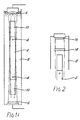
- the means of producing convergent ultrasonic beams can be by employing shaped, i.e. concave, transducer emitting surfaces, or by placing acoustic lenses in the path of transmission from the energy source. These two alternatives are illustrated schematically in Figs. 1 and 2, respectively, of the accompanying drawings.
- a working column 2 filled with liquid has inlet and outlet ports 4 for particles to be manipulated by an ultrasonic standing wave in the column while suspended in the liquid. Details of the manner of manipulation form no part of the present invention and will not be further described here.
- the standing wave is produced by opposed transducers 6 located coaxially beyond opposite ends of the column and having matched outputs.
- the column and the transducers are immersed in a liquid bath 8 which couples the transducer outputs to the liquid in the column while the bath is isolated from the column by liquid-tight seals 10.
- the walls of the column 2 and the seals 10 are acoustically transparent.
- Each transducer has a concave radiating face and so produces a convergent beam of ultrasonic energy having a constant energy density along its length, as described above. Consequently, the interference of the two beams produces a standing wave free of any significant degree of acoustic streaming over a substantial working length within the column.
- Fig. 2 illustrates one end of a similar arrangement in which, however, a planar radiating surface is provided on the transducer 16. Between it and the adjacent end of the column an acoustic lens 18 is placed of a material in which the acoustic velocity is higher than in the liquid.
- a plano-concave lens form produces a converging beam, and with an appropriate radius of curvature for the lens the beam can be given a constant energy density over its working length.
- an acoustic plano-concave lens made from polystyrene having a density of 1.09 gms/cm2, a modulus of elasticity at 23°C of 17 x 103 kg/cm2 and a sonic velocity of approximately 2350 meters per second.
- the lens had a diameter of 15 mm, a thickness of 6 mm at the periphery and an accurately co-axial concave surface of 620 mm radius of curvature.
- the plane surface of the lens was placed in contact with the plane surface of a 15 mm diameter barium titanate ceramic transducer having a resonant frequency of 4.4 MHz.
- the assembly was placed in water and the ultrasonic beam scanned along and across its axis using a Versiscan ultrasonic non-destructive testing scanning system. (Staveley, N.D.T. Technologies, Slough, England).
- a long focal zone was observed about 500 mm from the source.
- the transducer and acoustic lens mounted on a horizontal axis at one end of a water-filled trough and an ultrasound absorbing carpet was placed at the opposite end of the trough.
- the path of the ultrasound was observed through the transparent methyl methacrylate sides of the trough while very small crystals of potassium permanganate were allowed to fall through the water at or near the acoustic axis, in the area of the focal zone.
- the coloured trails of dissolved permanganate so formed indicated the stability of the water in that region.
Landscapes
- Physics & Mathematics (AREA)
- Engineering & Computer Science (AREA)
- Acoustics & Sound (AREA)
- Multimedia (AREA)
- Transducers For Ultrasonic Waves (AREA)
- Apparatuses For Generation Of Mechanical Vibrations (AREA)
- Separation Of Solids By Using Liquids Or Pneumatic Power (AREA)
- Measurement Of Velocity Or Position Using Acoustic Or Ultrasonic Waves (AREA)
- Ultra Sonic Daignosis Equipment (AREA)
- Saccharide Compounds (AREA)
Claims (11)
Priority Applications (1)
| Application Number | Priority Date | Filing Date | Title |
|---|---|---|---|
| AT87903377T ATE72907T1 (de) | 1986-05-27 | 1987-05-27 | Erzeugung eines ultraschallfeldes. |
Applications Claiming Priority (2)
| Application Number | Priority Date | Filing Date | Title |
|---|---|---|---|
| GB8612760 | 1986-05-27 | ||
| GB868612760A GB8612760D0 (en) | 1986-05-27 | 1986-05-27 | Ultrasonic field generation |
Publications (2)
| Publication Number | Publication Date |
|---|---|
| EP0268633A1 EP0268633A1 (de) | 1988-06-01 |
| EP0268633B1 true EP0268633B1 (de) | 1992-02-26 |
Family
ID=10598436
Family Applications (1)
| Application Number | Title | Priority Date | Filing Date |
|---|---|---|---|
| EP19870903377 Expired EP0268633B1 (de) | 1986-05-27 | 1987-05-27 | Erzeugung eines ultraschallfeldes |
Country Status (7)
| Country | Link |
|---|---|
| US (1) | US4941135A (de) |
| EP (1) | EP0268633B1 (de) |
| JP (1) | JP2880506B2 (de) |
| AT (1) | ATE72907T1 (de) |
| DE (1) | DE3776869D1 (de) |
| GB (1) | GB8612760D0 (de) |
| WO (1) | WO1987007421A1 (de) |
Cited By (1)
| Publication number | Priority date | Publication date | Assignee | Title |
|---|---|---|---|---|
| US11610783B2 (en) | 2014-07-30 | 2023-03-21 | Corning Incorporated | Ultrasonic tank and methods for uniform glass substrate etching |
Families Citing this family (7)
| Publication number | Priority date | Publication date | Assignee | Title |
|---|---|---|---|---|
| AT389235B (de) * | 1987-05-19 | 1989-11-10 | Stuckart Wolfgang | Verfahren zur reinigung von fluessigkeiten mittels ultraschall und vorrichtungen zur durchfuehrung dieses verfahrens |
| GB8912420D0 (en) * | 1989-05-31 | 1989-07-19 | Schram Cornelius J | Ultrasonic systems |
| DE4004711A1 (de) * | 1990-02-15 | 1991-08-22 | Peter Husten | Verfahren und vorrichtung zur entfernung von schadstoffen aus untergrund-formationen im erdboden |
| GB9005705D0 (en) * | 1990-03-14 | 1990-05-09 | Health Lab Service Board | Particle manipulation |
| US5147562A (en) * | 1990-12-17 | 1992-09-15 | The United States Of America As Represented By The Administrator Of The National Aeronautics And Space Administration | Acoustophoresis method and apparatus |
| US5803270A (en) * | 1995-10-31 | 1998-09-08 | Institute Of Paper Science & Technology, Inc. | Methods and apparatus for acoustic fiber fractionation |
| US5688406A (en) * | 1996-02-28 | 1997-11-18 | The United States Of America As Represented By The Secretary Of The Navy | Method and apparatus for separating particulate from a flowing fluid |
Family Cites Families (14)
| Publication number | Priority date | Publication date | Assignee | Title |
|---|---|---|---|---|
| US32062A (en) * | 1861-04-16 | George gatty | ||
| FR1100986A (fr) * | 1954-03-12 | 1955-09-27 | Perfectionnements aux appareils pour la séparation de corpuscules en suspension dans les gaz | |
| US3397936A (en) * | 1963-11-15 | 1968-08-20 | Marquardt Corp | Standing wave ultrasonic light cell modulator |
| WO1979000373A1 (en) * | 1977-12-12 | 1979-06-28 | Rca Corp | Acoustic variable focal length lens assembly |
| US4269067A (en) * | 1979-05-18 | 1981-05-26 | International Business Machines Corporation | Method and apparatus for focusing elastic waves converted from thermal energy |
| US4218921A (en) * | 1979-07-13 | 1980-08-26 | The United States Of America As Represented By The Administrator Of The National Aeronautics And Space Administration | Method and apparatus for shaping and enhancing acoustical levitation forces |
| US4280823A (en) * | 1979-11-13 | 1981-07-28 | Honeywell Inc. | Method and apparatus for sonic separation and analysis of components of a fluid mixture |
| JPS5943172B2 (ja) * | 1980-06-30 | 1984-10-20 | アロカ株式会社 | 超音波探触子 |
| US4423637A (en) * | 1980-12-18 | 1984-01-03 | Soloway Mahlon R | Ultrasonic testing instrument and method |
| USRE32062E (en) | 1981-01-06 | 1986-01-14 | Multiple field acoustic focusser | |
| US4445380A (en) * | 1982-07-21 | 1984-05-01 | Technicare Corporation | Selectable focus sphericone transducer and imaging apparatus |
| US4480324A (en) * | 1983-04-11 | 1984-10-30 | The United States Of America As Represented By The Secretary Of The Navy | Constant beamwidth frequency independent acoustic antenna |
| DE3481281D1 (de) * | 1983-10-31 | 1990-03-15 | Nat Res Dev | Beeinflussung von partikeln. |
| GB8417240D0 (en) * | 1984-07-06 | 1984-08-08 | Unilever Plc | Particle separation |
-
1986
- 1986-05-27 GB GB868612760A patent/GB8612760D0/en active Pending
-
1987
- 1987-05-27 WO PCT/GB1987/000364 patent/WO1987007421A1/en not_active Ceased
- 1987-05-27 JP JP62503135A patent/JP2880506B2/ja not_active Expired - Lifetime
- 1987-05-27 AT AT87903377T patent/ATE72907T1/de not_active IP Right Cessation
- 1987-05-27 EP EP19870903377 patent/EP0268633B1/de not_active Expired
- 1987-05-27 DE DE8787903377T patent/DE3776869D1/de not_active Expired - Lifetime
-
1989
- 1989-05-08 US US07/348,189 patent/US4941135A/en not_active Expired - Fee Related
Cited By (1)
| Publication number | Priority date | Publication date | Assignee | Title |
|---|---|---|---|---|
| US11610783B2 (en) | 2014-07-30 | 2023-03-21 | Corning Incorporated | Ultrasonic tank and methods for uniform glass substrate etching |
Also Published As
| Publication number | Publication date |
|---|---|
| WO1987007421A1 (en) | 1987-12-03 |
| EP0268633A1 (de) | 1988-06-01 |
| JP2880506B2 (ja) | 1999-04-12 |
| JPS63503407A (ja) | 1988-12-08 |
| ATE72907T1 (de) | 1992-03-15 |
| US4941135A (en) | 1990-07-10 |
| GB8612760D0 (en) | 1986-07-02 |
| DE3776869D1 (de) | 1992-04-02 |
Similar Documents
| Publication | Publication Date | Title |
|---|---|---|
| EP0270592B1 (de) | Teilchenmanipulation | |
| US5006266A (en) | Manipulating means utilizing ultrasonic wave energy for use with particulate material | |
| US5831166A (en) | Method of non-contact micromanipulation using ultrasound | |
| Whitworth et al. | Transport and harvesting of suspended particles using modulated ultrasound | |
| Gallego‐Juárez | Basic principles of ultrasound | |
| Tolt et al. | Separation devices based on forced coincidence response of fluid‐filled pipes | |
| US2770795A (en) | Acoustic log | |
| EP0268633B1 (de) | Erzeugung eines ultraschallfeldes | |
| Hatano et al. | High-frequency ultrasonic cleaning tank utilizing oblique incidence | |
| EP0480936A1 (de) | Verfahren und vorrichtung zum schützen eines schiffskörpers oder unterwasserbauwerks gegen biologische verschmutzung. | |
| Toulis | Acoustic refraction and scattering with compliant elements. I. Measurements in water | |
| KR102331585B1 (ko) | 초음파 조준장치 및 이를 이용한 초음파 조준방법 | |
| SU563623A1 (ru) | Звукопровод к ультразвуковому преобразователю | |
| Baer | ULTRASONIC TRANSDUCER ARRAYS FOR NONDESTRUCTIVE TESTING. | |
| Miller et al. | The influence of biophysical conditions on hemolysis near ultrasonically activated gas‐filled micropores | |
| Chamuel et al. | Propagation of Rayleigh and Scholte waves along edge of quarter‐space | |
| Defranould et al. | Ultrasonic array design and performance | |
| SU1272221A1 (ru) | Ультразвуковой наклонный преобразователь (его варианты) | |
| JPS57104856A (en) | Sonic microscope | |
| Gallego et al. | New advances in the generation of directional sonic and ultrasonic radiation | |
| GB703480A (en) | Means for launching beams of ultrasonic radiation in a medium | |
| Jongens et al. | Parametric Acoustic Array Application Using Liquids with Low Sound Speed | |
| Adler | saturation of acau3uc amplifical. ion in | |
| Koerber | SONICS AND ULTRASONICS | |
| SU471124A1 (ru) | Ультразвуковой излучатель |
Legal Events
| Date | Code | Title | Description |
|---|---|---|---|
| PUAI | Public reference made under article 153(3) epc to a published international application that has entered the european phase |
Free format text: ORIGINAL CODE: 0009012 |
|
| AK | Designated contracting states |
Kind code of ref document: A1 Designated state(s): AT BE CH DE FR GB IT LI LU NL SE |
|
| 17P | Request for examination filed |
Effective date: 19880520 |
|
| RAP1 | Party data changed (applicant data changed or rights of an application transferred) |
Owner name: NATIONAL RESEARCH DEVELOPMENT CORPORATION |
|
| 17Q | First examination report despatched |
Effective date: 19900222 |
|
| GRAA | (expected) grant |
Free format text: ORIGINAL CODE: 0009210 |
|
| AK | Designated contracting states |
Kind code of ref document: B1 Designated state(s): AT BE CH DE FR GB IT LI LU NL SE |
|
| PG25 | Lapsed in a contracting state [announced via postgrant information from national office to epo] |
Ref country code: LI Effective date: 19920226 Ref country code: CH Effective date: 19920226 Ref country code: BE Effective date: 19920226 |
|
| REF | Corresponds to: |
Ref document number: 72907 Country of ref document: AT Date of ref document: 19920315 Kind code of ref document: T |
|
| REF | Corresponds to: |
Ref document number: 3776869 Country of ref document: DE Date of ref document: 19920402 |
|
| ITF | It: translation for a ep patent filed | ||
| RAP2 | Party data changed (patent owner data changed or rights of a patent transferred) |
Owner name: BRITISH TECHNOLOGY GROUP PLC |
|
| REG | Reference to a national code |
Ref country code: GB Ref legal event code: 732 |
|
| ET | Fr: translation filed | ||
| REG | Reference to a national code |
Ref country code: CH Ref legal event code: PUE Owner name: BRITISH TECHNOLOGY GROUP PLC |
|
| PG25 | Lapsed in a contracting state [announced via postgrant information from national office to epo] |
Ref country code: LU Free format text: LAPSE BECAUSE OF NON-PAYMENT OF DUE FEES Effective date: 19920531 |
|
| REG | Reference to a national code |
Ref country code: CH Ref legal event code: PL |
|
| RAP4 | Party data changed (patent owner data changed or rights of a patent transferred) |
Owner name: BRITISH TECHNOLOGY GROUP LTD |
|
| NLT2 | Nl: modifications (of names), taken from the european patent patent bulletin |
Owner name: BRITISH TECHNOLOGY GROUP PLC TE LONDEN, GROOT-BRIT |
|
| PLBE | No opposition filed within time limit |
Free format text: ORIGINAL CODE: 0009261 |
|
| STAA | Information on the status of an ep patent application or granted ep patent |
Free format text: STATUS: NO OPPOSITION FILED WITHIN TIME LIMIT |
|
| BECN | Be: change of holder's name |
Effective date: 19920226 |
|
| 26N | No opposition filed | ||
| ITTA | It: last paid annual fee | ||
| EAL | Se: european patent in force in sweden |
Ref document number: 87903377.7 |
|
| PGFP | Annual fee paid to national office [announced via postgrant information from national office to epo] |
Ref country code: GB Payment date: 19980409 Year of fee payment: 12 |
|
| PGFP | Annual fee paid to national office [announced via postgrant information from national office to epo] |
Ref country code: FR Payment date: 19980416 Year of fee payment: 12 |
|
| PGFP | Annual fee paid to national office [announced via postgrant information from national office to epo] |
Ref country code: SE Payment date: 19980417 Year of fee payment: 12 Ref country code: DE Payment date: 19980417 Year of fee payment: 12 |
|
| PGFP | Annual fee paid to national office [announced via postgrant information from national office to epo] |
Ref country code: AT Payment date: 19980422 Year of fee payment: 12 |
|
| PGFP | Annual fee paid to national office [announced via postgrant information from national office to epo] |
Ref country code: NL Payment date: 19980423 Year of fee payment: 12 |
|
| PG25 | Lapsed in a contracting state [announced via postgrant information from national office to epo] |
Ref country code: GB Free format text: LAPSE BECAUSE OF NON-PAYMENT OF DUE FEES Effective date: 19990527 Ref country code: AT Free format text: LAPSE BECAUSE OF NON-PAYMENT OF DUE FEES Effective date: 19990527 |
|
| PG25 | Lapsed in a contracting state [announced via postgrant information from national office to epo] |
Ref country code: SE Free format text: LAPSE BECAUSE OF NON-PAYMENT OF DUE FEES Effective date: 19990528 |
|
| PG25 | Lapsed in a contracting state [announced via postgrant information from national office to epo] |
Ref country code: NL Free format text: LAPSE BECAUSE OF NON-PAYMENT OF DUE FEES Effective date: 19991201 |
|
| GBPC | Gb: european patent ceased through non-payment of renewal fee |
Effective date: 19990527 |
|
| EUG | Se: european patent has lapsed |
Ref document number: 87903377.7 |
|
| PG25 | Lapsed in a contracting state [announced via postgrant information from national office to epo] |
Ref country code: FR Free format text: LAPSE BECAUSE OF NON-PAYMENT OF DUE FEES Effective date: 20000131 |
|
| NLV4 | Nl: lapsed or anulled due to non-payment of the annual fee |
Effective date: 19991201 |
|
| PG25 | Lapsed in a contracting state [announced via postgrant information from national office to epo] |
Ref country code: DE Free format text: LAPSE BECAUSE OF NON-PAYMENT OF DUE FEES Effective date: 20000301 |
|
| REG | Reference to a national code |
Ref country code: FR Ref legal event code: ST |
|
| PG25 | Lapsed in a contracting state [announced via postgrant information from national office to epo] |
Ref country code: IT Free format text: LAPSE BECAUSE OF NON-PAYMENT OF DUE FEES Effective date: 20050527 |