EP0268689B1 - Detecteur de position a emetteur et recepteur radio - Google Patents
Detecteur de position a emetteur et recepteur radio Download PDFInfo
- Publication number
- EP0268689B1 EP0268689B1 EP87903742A EP87903742A EP0268689B1 EP 0268689 B1 EP0268689 B1 EP 0268689B1 EP 87903742 A EP87903742 A EP 87903742A EP 87903742 A EP87903742 A EP 87903742A EP 0268689 B1 EP0268689 B1 EP 0268689B1
- Authority
- EP
- European Patent Office
- Prior art keywords
- detecting
- signal
- needle
- circuit
- contact
- Prior art date
- Legal status (The legal status is an assumption and is not a legal conclusion. Google has not performed a legal analysis and makes no representation as to the accuracy of the status listed.)
- Expired - Lifetime
Links
- 230000003068 static effect Effects 0.000 claims description 11
- 239000004020 conductor Substances 0.000 claims description 10
- 239000003990 capacitor Substances 0.000 claims description 3
- 238000005259 measurement Methods 0.000 claims 3
- 238000001514 detection method Methods 0.000 claims 2
- 230000001419 dependent effect Effects 0.000 claims 1
- 238000003754 machining Methods 0.000 abstract description 12
- 230000005540 biological transmission Effects 0.000 abstract 1
- 239000012811 non-conductive material Substances 0.000 description 6
- 230000006835 compression Effects 0.000 description 4
- 238000007906 compression Methods 0.000 description 4
- 239000011810 insulating material Substances 0.000 description 4
- 239000013078 crystal Substances 0.000 description 2
- 238000010586 diagram Methods 0.000 description 2
- 238000010276 construction Methods 0.000 description 1
- 230000009977 dual effect Effects 0.000 description 1
- RTZKZFJDLAIYFH-UHFFFAOYSA-N ether Substances CCOCC RTZKZFJDLAIYFH-UHFFFAOYSA-N 0.000 description 1
- 150000002170 ethers Chemical class 0.000 description 1
- 238000000034 method Methods 0.000 description 1
- 230000008054 signal transmission Effects 0.000 description 1
Images


Classifications
-
- G—PHYSICS
- G01—MEASURING; TESTING
- G01B—MEASURING LENGTH, THICKNESS OR SIMILAR LINEAR DIMENSIONS; MEASURING ANGLES; MEASURING AREAS; MEASURING IRREGULARITIES OF SURFACES OR CONTOURS
- G01B7/00—Measuring arrangements characterised by the use of electric or magnetic techniques
- G01B7/002—Constructional details of contacts for gauges actuating one or more contacts
-
- G—PHYSICS
- G01—MEASURING; TESTING
- G01B—MEASURING LENGTH, THICKNESS OR SIMILAR LINEAR DIMENSIONS; MEASURING ANGLES; MEASURING AREAS; MEASURING IRREGULARITIES OF SURFACES OR CONTOURS
- G01B2210/00—Aspects not specifically covered by any group under G01B, e.g. of wheel alignment, caliper-like sensors
- G01B2210/58—Wireless transmission of information between a sensor or probe and a control or evaluation unit
Definitions
- the present invention relates to a position detector according to the preamble of claim 1.
- a position detector of such kind is known, for example from US Patent No. 4118 871 and has an external contact formed of electrically-insulated needle and the detected object so that the contact between the needle and the work closes the external contact to produce a detecting signal.
- Another position detector known from US Patent No 4153 998 has a needle which contacts with an object to be detected to detach its base portion from a seat surface keeping the static position of the needle so that it breaks the internal contact to produce a detecting signal.
- the object of the invention according to claim 4 to provide a position detector having advantages brought about by both the above position detector having the internal contact and the above position detector having the external contact.
- the position detector having the internal contact can detect the position of an object to be detected, independently of the property of the object to be detected, conductive or a non-conductive.
- This type of position detector cannot actuate its internal contact without time delay after the detecting needle and the object to be detected are brought in contact with each other. There is then a strong possibility that various errors may occur.
- this internal contact type position detector produces measured values that are considerably made different as compared with the external contact type position detector.
- the position detector having the external contact can detect at high accuracy the position of the object made of conductive material but it cannot detect the position of the object made of non-conductive material. Therefore, the object of this invention is to solve these problems.
- a detecting needle 20 made of conductive material is attached to the detecting head 43 in an electrically-insulated fashion and to be freely movable in a three-dimensional manner and also biased to a predetermined static position.
- the detecting head is provided with internal contacts 27 and 31 openable or closable when the detecting needle 20 moves from the static position.
- a first contact detecting circuit 45 including the external contact produces a first detecting signal A, for example, a signal of some specific frequency or amplitude.
- a second contact detecting circuit 47 including the internal contacts produces a second detecting signal B, for example, a signal having a frequency or amplitude different from that of the first detecting signal A.
- the receiving side controller 80 is supplied with a different compensating value whether or not the first signal A is delivered prior to the second signal B, and calculates a measured value, thus the third object of this invention being achieved.
- the receiver 70 can positively receive the detecting signal of a predetermined level.
- the FM wave is employed as the carrier wave of the detecting signal and the detecting signal is modulated by the double scale signal and transmitted through radio wave, it is possible to completely remove such a risk that the position detector is affected or mis-operated by extraneous noise.
- the receiving side apparatus receives the first detecting signal A prior to the second detecting signal B to thereby detect that the work is made of conductive material.
- the measured value is corrected by giving the measured value calculated from an input time point s of the detecting signal to a corrected value registered as a correcting value for the external contact.
- the external contact does not function as the contact so that the second detecting signal B is produced first at the time when the internal contact is actuated. Therefore, the absence of the first detecting signal A makes it possible to decide that the object 42 is made of non-conductive material.
- the measured value is corrected by giving the measured value calculated from the input time point s of the detecting signal to a corrected value registered as a correcting value for the internal contact.
- An advantage of this invention is the provision of a technique which can positively transmit a detecting signal by radio wave to a receiver located at a fixed position irrespective of the movement of the detecting head including the detecting needle and the transmitter.
- the position detector of this invention comprises a detecting head 43 having electrical detecting means 45 and 47 for detecting the contact between a detecting needle 20 and an object 42 to be detected as an electrical signal and a radio transmitter 50 for transmitting the detected electrical signal, a radio receiver 70 for receiving the above signal and a controller 80 located at a fixed position, wherein the output from the radio transmitter 50 is supplied to the detecting needle 20 itself.
- Another advantage of this invention is the provision of a position detector which can be prevented from being mis-operated when various extraneous noises are produced in the radio wave under the circumstances in which the position detector is operated.
- This ether advantage can be achieved by the thus constructed position detector in which the carrier wave for the detecting signal, which is transmitted and received through radio wave, is made an FM wave and the signal delivered from the transmitter 50 is modulated by a double scale signal.
- FIG. 1 is a cross-sectional view illustrating a structure of a detecting head in greater detail
- Fig. 2 is an exploded perspective view of a main portion showing a construction for supporting a detecting needle
- Fig. 3 is an electrical block diagram of the transmitting side
- Fig. 4 is an electrical block diagram of the receiving side
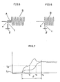
- Fig. 5 is a schematic representation illustrating a signal produced when a work is made of conductive material
- Fig. 6 is a schematic representation illustrating a signal produced when the work is made of non-conductive material
- Fig. 7 is a schematic representation used to explain that the detecting signals rise at different timings.
- reference numeral 1 designates the head housing, 4 the battery, 8 the inside casing, 20 the detecting needle, 21 the supporting disk, 22 the insulating material, 23 the hemispherically-shaped protrusions, 24, 25 and 26 the seats, 27 the internal contact at the detecting needle side, 28 the insulating material, 31 the internal contact at the housing side, 33 the compression spring, 35 the auxiliary spring, 42 the object to be detected, 43 the detecting head, 45 the first detecting circuit, 47 the second detecting circuit, 50 the transmitter, 55 the double scale signal generator, 56 and 57 the signal terminals thereof, 70 the receiver, 77 the signal discriminating circuit and 80 the CNC apparatus for the machine tool.
- a head housing 1 is provided with a shank 2 and a display LED 3.
- the head housing 1 incorporates therein a battery 4 and has a battery lid 5.
- the head housing 1 has a bottom plate 7 having an opening 6 formed through its center.
- An inside casing 8 has an opening 9 formed through the center of a bottom plate 10 of the inside casing 8.
- Three screw seats 11 are embedded on the bottom plate 7 of the head housing with an angular spacing of 120°.
- Three fastening screws 12 are screwed through the bottom plate 7 of the head housing to the bottom plate 10 of the inside casing so as to have a phase difference of 60° relative to the screw seats 11.
- the inside casing 8 is suppressed to the screw seats 11 by the fastening screws 12 and supported thereby and is built into the head housing 1 with a certain clearance 13 therebetween.
- Three fine adjusting screws 14 are secured to the cylindrical portion of the head housing with an angular spacing of 120° in an opposing relation to the cylindrical portion of the inside casing. These fine adjusting screws move the inside casing 8 to fine adjust the inclination of the detecting needle 20.
- the detecting needle 20 is supported by a supporting disk 21 and an insulating material 22 is interposed between the detecting needle 20 and the supporting disk 21.
- the detecting needle 20 is secured to the supporting disk 21 and extended through the openings 9 and 6 to the outside of the head housing 1.
- Hemispherically-shaped protrusions 23 are implanted on the lower surface of the supporting disk 21 with an angular spacing of 120°.
- On the upper surface of the bottom plate 10 of the inside casing there are formed a first seat 24 formed of three balls, a second V-shaped groove seat 25 and a third planar seat 26 in an opposing relation to the protrusions 23 as shown in Fig. 2.
- the internal contact 27 is secured to the base end portion of the detecting needle 20 through an insulating material 28.
- a spring stop 29 is engaged with the inside casing 8, and a contact holder 30 holds an internal contact 31 at the housing side.
- This internal contact 31 is biased downwards by a spring 32, and a compression spring 33 is stretched between the spring stop 29 and the supporting disk 21 to urge the supporting disk 21 downwards.
- the housing side internal contact 31 is inserted into a conical-shaped opening 34 of the contact holder 30 so as to be retractable upwards.
- the detecting needle 20 can keep a stable static position by urging three hemispherically-shaped protrusions 23 against the first to third seats 24, 25 and 26 by the compression spring 33.
- Two of three tension springs 35 are located near both sides of the first seat 24 and the remainder is located adjacent the second seat 25 at the side of the third seat 26. Since the hemispherically-shaped protrusions 23 are urged against the seats 24, 25 and 26 by the auxiliary springs 35, the detecting needle 20 can return to the stable static position as positively as possible.
- reference numerals 36 designate sleeves through which the tension springs 35 pass. Both ends of the tension springs 35 are respectively abutted against the supporting disk 21 side and the inside casing bottom plate 10 side by screws 37 and 38.
- reference numeral 40 designates a tool spindle of the machining tool, 41 a table of the machining tool and 42 a work set on the table.
- Reference numeral 43 generally designates the detecting head shown in Fig. 1. The detecting head 43 is mounted to the tool spindle 40 by means of the shank 2. The shank 2 and the work 42 are electrically conducted through the main body of the machining tool.
- the supporting disk 21 is held by the biasing force of the compression spring 33 and the tension springs 35 at the static position and is also movable in the three-dimension against the biasing forces of the springs 33 and 35.
- the cathode of the battery 4 is grounded through the head housing l of the detecting head 43 while the anode thereof is connected to the detecting needle 20 through a resistor 44 to form the first detecting circuit 45, and is also connected to the contact 27 of the base end portion of the detecting needle through a resistor 46 to form the second detecting circuit 47.
- Reference numeral 50 generally designates the transmitter which comprises a crystal oscillator 51, an oscillating circuit 52, a frequency modulating circuit 53, an amplifying circuit 54 and a DTMF (dual tone multi-frequency) circuit 55.
- the DTMF circuit 55 is adapted to produce 16 double scale signals in 4 x 4 combinations of scales selected from two sets of four different kinds of scale groups and produces, when receiving input signals at its signal terminals 56 and 57, double scale signals set at the respective terminals 56 and 57.
- the input signals are simultaneously supplied to the terminals 26 and 27, the input signal applied to the terminal 27 overrides the other.
- the output from the amplifying circuit 54 is supplied through a mutual inductance 58, a resistor 59 and a capacitor 60 to the detecting needle 20.
- the detecting needle 20 itself functions as the antenna for the transmitter 50.
- Transistors 61 and 62 are provided to supply detecting signals to the DTMF circuit 55.
- the bases thereof are connected to the detecting needle 20 and to the contact 27 provided at the base end portion of the detecting needle, the emitters thereof are connected to the anode of the battery 4 and the collectors thereof are connected to the signal terminals 56 and 57 of the DTMF circuit.
- reference numeral 69 designates a receiving side antenna
- reference numeral 70 generally designates a receiver which comprises a high frequency amplifying circuit, a crystal oscillator 72, a local oscillator circuit 73, a frequency mixing circuit 74, an intermediate frequency amplifying circuit 75 and a demodulating circuit 76.
- Reference numeral 77 designates a signal discriminating circuit, and the double scale signals the same as those set in the DTMF circuit 55 at the transmitter side are set in this signal discriminating circuit. The signal discriminating circuit produces an output only when the received signal coincides with the thus se double scale signal.
- Reference numeral 78 designates a delay circuit, 81 an AND gate, 79 an interface circuit and 80 a CNC apparatus for machining tool.
- this CNC apparatus there are registered in advance a correcting value for the external contact formed of a pair of the work and the detecting needle and a correcting value for the internal contact formed of the contacts 27 and 31.
- the correcting values are set in each of the detecting heads 43 used.
- the first detecting circuit 45 formed from the anode of the battery 4 through the resistor 44, the detecting needle 20, the work 42, the main body of the machining tool and the shank 2 to the cathode of the battery is closed to flow a current through this circuit.
- This current causes a potential difference across the resistor 44.
- the potential difference turns the transistor 61 on and hence a detecting signal is supplied to the first signal terminal 56 of the DTMF circuit 55.
- This signal is converted into the double scale signal set at the terminal 56 and then fed to the frequency modulating circuit 53, whereby the FM carrier wave from the oscillating circuit 52 is thereby modulated and the modulated signal is amplified by the amplifying circuit 54 and then delivered.
- the high frequency signal from the amplifying circuit 54 is supplied through the mutual inductance 58 and the capacitor 60 to the detecting needle 20. At that time, since the detecting needle 20 is in contact with the work 42, the high frequency signal from the amplifying circuit 54 is supplied to the work 42 and the main body of the machining tool, causing the whole of the machining tool to function as an antenna to radiate a radio wave. The radio wave is received by the receiving side antenna 69.
- the detecting head 43 continues moving to incline the detecting needle 20, whereby the internal contacts 27 and 31 come in contact with each other to permit closings the second detecting circuit 47. Then, a detecting signal is supplied to the second signal terminal 57 of the DTMF circuit 55 and the signal transmitted from the transmitter 50 is converted into the output signal set at the second signal terminal 57. That is, as shown in-Fig. 5, the transmitter 50 delivers the first signal A and then the second signal B.
- the external contact formed of the work 42 and the detecting needle 20 does not function so that the transmitter 50 delivers only the second signal B as shown in Fig. 6.
- the second signal is delivered with a time delay of a certain time period after the work 42 and the detecting needle 20 come in contact with each other.
- the output signal in Fig. 5 or 6 is received by the receiver 70.
- the signal discriminating circuit 77 identifies whether the received signal is the signal shown in Fig. 5 or 6 and then supplies its identifying signal a to the CNC apparatus 80.
- the delay circuit 78 supplies the detecting signal through the interface circuit 79 to the CNC apparatus 80 so long as the identifying signal a is delivered at a time point t3 which is behind a time point at which the signal is first detected (time point t0 in Fig. 7) by a predetermined time ⁇ .
- the reason that the delay circuit 78 is provided is to remove a signal identifying timing (t1 or t2 in Fig. 7) error caused by the difference of the leading edges of the detecting signals as shown in Fig. 7.
- the delay time ⁇ at that time is corrected by registering this delay time in the CNC apparatus 80 as a correcting value.
- L1 represents the signal detecting level of the delay circuit 78 and L2 the signal identifying level of the discriminating circuit 77.
- the CNC apparatus 80 incessantly monitors the positions of the tool spindle 40 and the table 41 and controls the same so that when receiving the signal from the interface circuit 79, it latches the positions of the tool spindle 40 and the table 41 at that time point, produces the correcting value registered for the external or internal contact selected by the identifying signal a and calculates the position of the work 42. At that time, the delay time ⁇ is also corrected.
- the electrical signal generated by the contact between the contact needle mounted on the tool spindle and the work can be radiated as a radio wave while using the machining tool itself as the antenna by utilizing the above contact. Therefore, irrespective of the positional relationship among the moving detecting needle, the transmitter and the work, the receiver located at the fixed position can always receive the constant and stable signal. Thus, the detecting signal can be transmitted by the radio wave stably and accurately and the cumbersome wiring work for cables becomes unnecessary. Also, there is no risk that the signal transmission is hindered by the directivity of the antenna and its positional relationship relative to the work. In addition, the consumption of the battery at the transmitter side can be reduced.
- the single detecting apparatus can detect the position of the work independently of the conductive or non-conductive material which makes the work.
- the internal contact type apparatus When the internal contact type apparatus is used, its measuring accuracy can be avoided from being lowered as much as possible, and the position of the work can be detected with highest accuracy in accordance with the property of the work.
- the delay circuit is provided in the receiver side and the delay amount thereof is finally corrected by the previously-registered correcting value to calculate the measured value, the error brought about when the signals rise at different timings can be removed, thus making it possible to detect the position more accurately.
- the main spring and the three auxiliary springs are used to place the detecting needle in its static position, the detecting needle can be returned to the static position with high accuracy.
- the static position of the detecting needle can be fine adjusted by the fine adjustment screw so that the position can be detected with extremely high accuracy.
Landscapes
- Physics & Mathematics (AREA)
- General Physics & Mathematics (AREA)
- Measurement Of Length, Angles, Or The Like Using Electric Or Magnetic Means (AREA)
- Machine Tool Sensing Apparatuses (AREA)
- Length Measuring Devices With Unspecified Measuring Means (AREA)
Abstract
Claims (5)
- Détecteur de position comprenant une tête détectrice (43), une aiguille détectrice (20) faite d'une matière conductrice et montée sur ladite tête détectrice, un émetteur radio (50) logé dans ladite tête détectrice, et un récepteur (70) pour recevoir un signal émis à partir dudit émetteur radio, la sortie dudit émetteur radio étant couplée à ladite aiguille détectrice, un circuit détecteur qui en utilisation est fermé par le contact entre ladite aiguille détectrice (20) et ledit objet détecté lorsque ledit objet (42) est fait d'une matière conductrice et un élément de commutation (61 et/ou 62) pour délivrer un courant de mise en oeuvre audit émetteur radio (50) en réponse à la fermeture dudit circuit détecteur, dans lequel une sortie dudit émetteur radio (50) est couplée par l'intermédiaire d'une inductance mutuelle (58) et d'un condensateur (60) à ladite aiguille détectrice (20), laquelle aiguille fonctionne comme une antenne pour l'émetteur ; et une unité de commande (80) pour une mesure de position utilisant les signaux reçus par le récepteur (70),
caractérisé en ce que : ladite aiguille détectrice (20) est montée sur ladite tête détectrice (43) de manière A être librement mobile de façon tridimensionnelle et est rappelée vers une position statique prédéterminée, ladite aiguille détectrice étant fixée d'une façon isolante de l'électricité à un boîtier de tête (1) ; en ce que ladite tête détectrice (43) possède des contacts internes incorporés (27 et 31) qui sont fermés ou ouverts Par le déplacement de ladite aiguille détectrice (20), et un second circuit détecteur (47) qui est fermé par la manoeuvre desdits contacts internes ; en ce que l'émetteur (50) est conçu pour fournir un premier signal de détection (A) lorsque ledit premier circuit de détection (45) est fermé et un second signal de détection (B) lorsque ledit second circuit de détection (47) est fermé ; en ce qu'un circuit de discrimination de signal (77) est prévu pour identifier si une sortie dudit récepteur (70) contient lesdits premier signal (A) et second signal (B) ou ledit second signal (B) seul et pour fournir un signal d'identification (a) à une unité de commande (80) pour une mesure de position, l'unité de commande étant conçue pour appliquer à une valeur mesurée une valeur de correction différente pour corriger ladite mesure de position en fonction de la détection dudit second signal de détection (a) à l'intérieur d'une certaine période de temps après la détection dudit premier signal de détection (A). - Détecteur de position selon la revendication 1, dans lequel ledit premier circuit de détection (45) comporte ladite aiguille comme contact externe.
- Détecteur de position Belon la revendication 1 ou la revendication 2, dans lequel ladite aiguille détectrice mobile actionne lesdits contacts internes de telle manière que lors du contact d'un objet par l'aiguille le second circuit (47) soit fermé.
- Détecteur de position selon l'une quelconque des revendications 1 à 3, dans lequel une onde porteuse pour lesdits émetteur et récepteur est une onde FM (à modulation de fréquence).
- Détecteur de position selon l'une quelconque des revendications 1 à 4, dans lequel ledit signal de détection émis par ledit émetteur (50) est un signal modulé par un signal à double gamme.
Applications Claiming Priority (2)
| Application Number | Priority Date | Filing Date | Title |
|---|---|---|---|
| JP61131620A JPH0765883B2 (ja) | 1986-06-05 | 1986-06-05 | 無線送受信器を有する位置検出装置 |
| JP131620/86 | 1986-06-05 |
Publications (3)
| Publication Number | Publication Date |
|---|---|
| EP0268689A1 EP0268689A1 (fr) | 1988-06-01 |
| EP0268689A4 EP0268689A4 (fr) | 1989-01-26 |
| EP0268689B1 true EP0268689B1 (fr) | 1993-03-24 |
Family
ID=15062313
Family Applications (1)
| Application Number | Title | Priority Date | Filing Date |
|---|---|---|---|
| EP87903742A Expired - Lifetime EP0268689B1 (fr) | 1986-06-05 | 1987-06-04 | Detecteur de position a emetteur et recepteur radio |
Country Status (5)
| Country | Link |
|---|---|
| US (1) | US4864294A (fr) |
| EP (1) | EP0268689B1 (fr) |
| JP (1) | JPH0765883B2 (fr) |
| DE (1) | DE3785004T2 (fr) |
| WO (1) | WO1987007712A1 (fr) |
Cited By (3)
| Publication number | Priority date | Publication date | Assignee | Title |
|---|---|---|---|---|
| WO1990001672A1 (fr) * | 1988-08-08 | 1990-02-22 | Ford Motor Company Limited | Dispositif de mesure d'ecartement et d'alignement |
| EP0506318A1 (fr) * | 1991-03-29 | 1992-09-30 | Renishaw Metrology Limited | Dispositif de transmission de signaux pour sonde à déclenchement |
| EP0872787A1 (fr) * | 1997-04-14 | 1998-10-21 | Renishaw plc | Système de capteur programmable |
Families Citing this family (13)
| Publication number | Priority date | Publication date | Assignee | Title |
|---|---|---|---|---|
| JPH074735B2 (ja) * | 1989-01-20 | 1995-01-25 | 大昭和精機株式会社 | 接触検出装置 |
| JPH04285804A (ja) * | 1991-03-13 | 1992-10-09 | Taisei Giken:Kk | Nc加工機を利用した製品寸法の測定方法 |
| US5369449A (en) * | 1991-11-08 | 1994-11-29 | Matsushita Electric Industrial Co., Ltd. | Method for predicting move compensation |
| USRE39279E1 (en) * | 1991-11-08 | 2006-09-12 | Matsushita Electric Industrial Co., Ltd. | Method for determining motion compensation |
| US5517190A (en) * | 1994-02-03 | 1996-05-14 | Gunn; Colin N. | Physical measurement from changes in reactance |
| US5541588A (en) * | 1994-08-01 | 1996-07-30 | Metrol Co., Ltd. | Control signal transfer device for a position detecting sensor |
| IT1279590B1 (it) * | 1995-05-11 | 1997-12-16 | Marposs Spa | Sistema e metodo di trasmissione di segnali via etere fra una testa di controllo e un ricevitore remoto |
| US5905440A (en) * | 1997-12-19 | 1999-05-18 | Battelle Memorial Institute | Acoustic emission severance detector and method |
| US7319396B2 (en) * | 2004-08-16 | 2008-01-15 | Abr, Llc | RFID transducer alignment system |
| ITBO20060031A1 (it) | 2006-01-18 | 2007-07-19 | Marposs Spa | Sistema e metodo di trasmissione a distanza di segnali via etere per sonde di controllo |
| US20070213705A1 (en) * | 2006-03-08 | 2007-09-13 | Schmid Peter M | Insulated needle and system |
| EP2028439A1 (fr) * | 2007-07-26 | 2009-02-25 | Renishaw plc | Appareil de mesure pouvant être désactivé |
| US8434392B1 (en) * | 2009-09-24 | 2013-05-07 | Virtual Dial Indicator, LLC. | Wireless sensor and monitoring system |
Citations (1)
| Publication number | Priority date | Publication date | Assignee | Title |
|---|---|---|---|---|
| JPS587509A (ja) * | 1981-06-30 | 1983-01-17 | レニシヨウ・エレクトリカル・リミテツド | 加工片測定用プロ−ブ |
Family Cites Families (10)
| Publication number | Priority date | Publication date | Assignee | Title |
|---|---|---|---|---|
| GB1445977A (en) * | 1972-09-21 | 1976-08-11 | Rolls Royce | Probes |
| GB1499003A (en) * | 1975-03-20 | 1978-01-25 | Rolls Royce | Displacement gauge |
| US4118871A (en) * | 1978-06-13 | 1978-10-10 | Kearney & Trecker Corporation | Binary inspection probe for numerically controlled machine tools |
| US4401945A (en) * | 1981-04-30 | 1983-08-30 | The Valeron Corporation | Apparatus for detecting the position of a probe relative to a workpiece |
| JPS57179105U (fr) * | 1981-05-11 | 1982-11-13 | ||
| JPS5818101A (ja) * | 1981-07-27 | 1983-02-02 | Nippon Denzai Kogyo Kenkyusho:Kk | タツチセンサ− |
| DE3382579T2 (de) * | 1982-03-05 | 1993-01-21 | Sony Magnescale Inc | Vorrichtung zum bestimmen der lage der oberflaechen eines festen objektes. |
| US4509266A (en) * | 1982-06-14 | 1985-04-09 | Gte Valeron Corporation | Touch probe |
| US4693110A (en) * | 1985-06-06 | 1987-09-15 | Gte Valeron Corporation | Method and apparatus for testing the operability of a probe |
| CH664216A5 (fr) * | 1985-10-14 | 1988-02-15 | Tesa Sa | Dispositif de palpage pour une machine a mesurer des pieces conductrices montees sur une table de mesure. |
-
1986
- 1986-06-05 JP JP61131620A patent/JPH0765883B2/ja not_active Expired - Fee Related
-
1987
- 1987-06-04 EP EP87903742A patent/EP0268689B1/fr not_active Expired - Lifetime
- 1987-06-04 WO PCT/JP1987/000355 patent/WO1987007712A1/fr not_active Ceased
- 1987-06-04 US US07/148,505 patent/US4864294A/en not_active Expired - Lifetime
- 1987-06-04 DE DE87903742T patent/DE3785004T2/de not_active Expired - Lifetime
Patent Citations (1)
| Publication number | Priority date | Publication date | Assignee | Title |
|---|---|---|---|---|
| JPS587509A (ja) * | 1981-06-30 | 1983-01-17 | レニシヨウ・エレクトリカル・リミテツド | 加工片測定用プロ−ブ |
Cited By (6)
| Publication number | Priority date | Publication date | Assignee | Title |
|---|---|---|---|---|
| WO1990001672A1 (fr) * | 1988-08-08 | 1990-02-22 | Ford Motor Company Limited | Dispositif de mesure d'ecartement et d'alignement |
| EP0506318A1 (fr) * | 1991-03-29 | 1992-09-30 | Renishaw Metrology Limited | Dispositif de transmission de signaux pour sonde à déclenchement |
| FR2674659A1 (fr) * | 1991-03-29 | 1992-10-02 | Renishan Metrology Ltd | Dispositif de transmission de signaux pour sonde a declenchement. |
| US5279042A (en) * | 1991-03-29 | 1994-01-18 | Renishaw Metrology Limited | Signal transmission system for trigger probe |
| EP0872787A1 (fr) * | 1997-04-14 | 1998-10-21 | Renishaw plc | Système de capteur programmable |
| US6301796B1 (en) | 1997-04-14 | 2001-10-16 | Renishaw Plc | Programmable probe system |
Also Published As
| Publication number | Publication date |
|---|---|
| EP0268689A1 (fr) | 1988-06-01 |
| JPS62287104A (ja) | 1987-12-14 |
| JPH0765883B2 (ja) | 1995-07-19 |
| DE3785004T2 (de) | 1993-10-21 |
| DE3785004D1 (de) | 1993-04-29 |
| WO1987007712A1 (fr) | 1987-12-17 |
| US4864294A (en) | 1989-09-05 |
| EP0268689A4 (fr) | 1989-01-26 |
Similar Documents
| Publication | Publication Date | Title |
|---|---|---|
| EP0268689B1 (fr) | Detecteur de position a emetteur et recepteur radio | |
| KR820000477B1 (ko) | 궤도 도란스를 가진 스핀들 프로브 | |
| US4973912A (en) | Method for contactless measurement of a resistance arranged in the secondary circuit of a transformer and device for carrying out the method | |
| US4631546A (en) | Electronically rotated antenna apparatus | |
| US5001430A (en) | Apparatus for locating concealed electrical conductors | |
| US3743853A (en) | Adjustable proximity sensor | |
| IE802333L (en) | Measurement shunt with compensation for induced error¹voltages | |
| EP0088596B1 (fr) | Appareil pour déterminer la position de la surface d'un objet solide | |
| WO2000044077A3 (fr) | Systeme permettant de mesurer l'impedance de transfert | |
| HU0000749D0 (en) | Equipment for determinating r.p.m. of a rotating element | |
| US5191348A (en) | Radar detector performance verification method and apparatus | |
| EP0183520B1 (fr) | Système d'antenne pour véhicule | |
| US4283714A (en) | Magnetic keyboard system | |
| KR930006645B1 (ko) | 원격표적 탐지시스템 | |
| JP2523984Y2 (ja) | 位置検出装置 | |
| US5541588A (en) | Control signal transfer device for a position detecting sensor | |
| EP0384029A1 (fr) | Système pour détecter l'entrée en contact d'une machine-outil | |
| US7515090B2 (en) | High-frequency position/path sensor for detecting the approach of an object and method for detecting the approach of an object | |
| JPH0239205Y2 (fr) | ||
| US5541507A (en) | Device for detecting the position of a magnet by analyzing movement of a current-fed coil disposed in the magnetic field of the magnet | |
| AU7009887A (en) | Measuring distances on an object | |
| US4224820A (en) | Frequency deviation meter for timepieces | |
| US2997710A (en) | Direction finder equipment | |
| US4733166A (en) | Apparatus for measuring the moisture content of moving materials | |
| US12306231B2 (en) | Apparatus and a method for testing radio-frequency tags |
Legal Events
| Date | Code | Title | Description |
|---|---|---|---|
| PUAI | Public reference made under article 153(3) epc to a published international application that has entered the european phase |
Free format text: ORIGINAL CODE: 0009012 |
|
| AK | Designated contracting states |
Kind code of ref document: A1 Designated state(s): DE FR GB IT |
|
| 17P | Request for examination filed |
Effective date: 19880607 |
|
| A4 | Supplementary search report drawn up and despatched |
Effective date: 19890126 |
|
| 17Q | First examination report despatched |
Effective date: 19901022 |
|
| GRAA | (expected) grant |
Free format text: ORIGINAL CODE: 0009210 |
|
| AK | Designated contracting states |
Kind code of ref document: B1 Designated state(s): DE FR GB IT |
|
| ITF | It: translation for a ep patent filed | ||
| REF | Corresponds to: |
Ref document number: 3785004 Country of ref document: DE Date of ref document: 19930429 |
|
| ET | Fr: translation filed | ||
| PLBE | No opposition filed within time limit |
Free format text: ORIGINAL CODE: 0009261 |
|
| STAA | Information on the status of an ep patent application or granted ep patent |
Free format text: STATUS: NO OPPOSITION FILED WITHIN TIME LIMIT |
|
| 26N | No opposition filed | ||
| PGFP | Annual fee paid to national office [announced via postgrant information from national office to epo] |
Ref country code: GB Payment date: 19950515 Year of fee payment: 9 |
|
| PGFP | Annual fee paid to national office [announced via postgrant information from national office to epo] |
Ref country code: FR Payment date: 19950619 Year of fee payment: 9 |
|
| PGFP | Annual fee paid to national office [announced via postgrant information from national office to epo] |
Ref country code: DE Payment date: 19950830 Year of fee payment: 9 |
|
| PG25 | Lapsed in a contracting state [announced via postgrant information from national office to epo] |
Ref country code: GB Effective date: 19960604 |
|
| GBPC | Gb: european patent ceased through non-payment of renewal fee |
Effective date: 19960604 |
|
| PG25 | Lapsed in a contracting state [announced via postgrant information from national office to epo] |
Ref country code: FR Effective date: 19970228 |
|
| PG25 | Lapsed in a contracting state [announced via postgrant information from national office to epo] |
Ref country code: DE Effective date: 19970301 |
|
| REG | Reference to a national code |
Ref country code: FR Ref legal event code: ST |
|
| PG25 | Lapsed in a contracting state [announced via postgrant information from national office to epo] |
Ref country code: IT Free format text: LAPSE BECAUSE OF NON-PAYMENT OF DUE FEES;WARNING: LAPSES OF ITALIAN PATENTS WITH EFFECTIVE DATE BEFORE 2007 MAY HAVE OCCURRED AT ANY TIME BEFORE 2007. THE CORRECT EFFECTIVE DATE MAY BE DIFFERENT FROM THE ONE RECORDED. Effective date: 20050604 |