EP0268758A2 - Mandrin à forer - Google Patents
Mandrin à forer Download PDFInfo
- Publication number
- EP0268758A2 EP0268758A2 EP87112787A EP87112787A EP0268758A2 EP 0268758 A2 EP0268758 A2 EP 0268758A2 EP 87112787 A EP87112787 A EP 87112787A EP 87112787 A EP87112787 A EP 87112787A EP 0268758 A2 EP0268758 A2 EP 0268758A2
- Authority
- EP
- European Patent Office
- Prior art keywords
- chuck
- drill
- sleeve
- adapter shaft
- axially
- Prior art date
- Legal status (The legal status is an assumption and is not a legal conclusion. Google has not performed a legal analysis and makes no representation as to the accuracy of the status listed.)
- Granted
Links
- 238000006073 displacement reaction Methods 0.000 claims abstract description 13
- 230000009471 action Effects 0.000 claims abstract description 5
- 229910000831 Steel Inorganic materials 0.000 claims description 12
- 239000010959 steel Substances 0.000 claims description 12
- 230000008878 coupling Effects 0.000 claims description 8
- 238000010168 coupling process Methods 0.000 claims description 8
- 238000005859 coupling reaction Methods 0.000 claims description 8
- 238000005553 drilling Methods 0.000 description 7
- 238000002347 injection Methods 0.000 description 2
- 239000007924 injection Substances 0.000 description 2
- 238000004519 manufacturing process Methods 0.000 description 2
- 230000007246 mechanism Effects 0.000 description 2
- 210000001331 nose Anatomy 0.000 description 2
- 101100063504 Mus musculus Dlx2 gene Proteins 0.000 description 1
- 241001494479 Pecora Species 0.000 description 1
- 230000008901 benefit Effects 0.000 description 1
- 239000000969 carrier Substances 0.000 description 1
- 238000010276 construction Methods 0.000 description 1
- 230000000694 effects Effects 0.000 description 1
- 230000001771 impaired effect Effects 0.000 description 1
- 239000002184 metal Substances 0.000 description 1
- 238000000034 method Methods 0.000 description 1
- 230000008569 process Effects 0.000 description 1
Images


Classifications
-
- B—PERFORMING OPERATIONS; TRANSPORTING
- B23—MACHINE TOOLS; METAL-WORKING NOT OTHERWISE PROVIDED FOR
- B23B—TURNING; BORING
- B23B31/00—Chucks; Expansion mandrels; Adaptations thereof for remote control
- B23B31/02—Chucks
- B23B31/10—Chucks characterised by the retaining or gripping devices or their immediate operating means
- B23B31/12—Chucks with simultaneously-acting jaws, whether or not also individually adjustable
- B23B31/1207—Chucks with simultaneously-acting jaws, whether or not also individually adjustable moving obliquely to the axis of the chuck in a plane containing this axis
- B23B31/123—Chucks with simultaneously-acting jaws, whether or not also individually adjustable moving obliquely to the axis of the chuck in a plane containing this axis with locking arrangements
-
- B—PERFORMING OPERATIONS; TRANSPORTING
- B25—HAND TOOLS; PORTABLE POWER-DRIVEN TOOLS; MANIPULATORS
- B25D—PERCUSSIVE TOOLS
- B25D17/00—Details of, or accessories for, portable power-driven percussive tools
- B25D17/005—Attachments or adapters placed between tool and hammer
-
- Y—GENERAL TAGGING OF NEW TECHNOLOGICAL DEVELOPMENTS; GENERAL TAGGING OF CROSS-SECTIONAL TECHNOLOGIES SPANNING OVER SEVERAL SECTIONS OF THE IPC; TECHNICAL SUBJECTS COVERED BY FORMER USPC CROSS-REFERENCE ART COLLECTIONS [XRACs] AND DIGESTS
- Y10—TECHNICAL SUBJECTS COVERED BY FORMER USPC
- Y10T—TECHNICAL SUBJECTS COVERED BY FORMER US CLASSIFICATION
- Y10T279/00—Chucks or sockets
- Y10T279/17—Socket type
- Y10T279/17042—Lost motion
- Y10T279/17068—Rotary socket
-
- Y—GENERAL TAGGING OF NEW TECHNOLOGICAL DEVELOPMENTS; GENERAL TAGGING OF CROSS-SECTIONAL TECHNOLOGIES SPANNING OVER SEVERAL SECTIONS OF THE IPC; TECHNICAL SUBJECTS COVERED BY FORMER USPC CROSS-REFERENCE ART COLLECTIONS [XRACs] AND DIGESTS
- Y10—TECHNICAL SUBJECTS COVERED BY FORMER USPC
- Y10T—TECHNICAL SUBJECTS COVERED BY FORMER US CLASSIFICATION
- Y10T279/00—Chucks or sockets
- Y10T279/17—Socket type
- Y10T279/17042—Lost motion
- Y10T279/17076—Spreading elements
-
- Y—GENERAL TAGGING OF NEW TECHNOLOGICAL DEVELOPMENTS; GENERAL TAGGING OF CROSS-SECTIONAL TECHNOLOGIES SPANNING OVER SEVERAL SECTIONS OF THE IPC; TECHNICAL SUBJECTS COVERED BY FORMER USPC CROSS-REFERENCE ART COLLECTIONS [XRACs] AND DIGESTS
- Y10—TECHNICAL SUBJECTS COVERED BY FORMER USPC
- Y10T—TECHNICAL SUBJECTS COVERED BY FORMER US CLASSIFICATION
- Y10T279/00—Chucks or sockets
- Y10T279/17—Socket type
- Y10T279/17042—Lost motion
- Y10T279/17094—Sleeve type retainer
-
- Y—GENERAL TAGGING OF NEW TECHNOLOGICAL DEVELOPMENTS; GENERAL TAGGING OF CROSS-SECTIONAL TECHNOLOGIES SPANNING OVER SEVERAL SECTIONS OF THE IPC; TECHNICAL SUBJECTS COVERED BY FORMER USPC CROSS-REFERENCE ART COLLECTIONS [XRACs] AND DIGESTS
- Y10—TECHNICAL SUBJECTS COVERED BY FORMER USPC
- Y10T—TECHNICAL SUBJECTS COVERED BY FORMER US CLASSIFICATION
- Y10T279/00—Chucks or sockets
- Y10T279/17—Socket type
- Y10T279/17615—Obliquely guided reciprocating jaws
- Y10T279/17623—Threaded sleeve and jaw
- Y10T279/17632—Conical sleeve
Definitions
- the invention relates to a drill chuck with an adapter shaft designed to be received in the tool holder of a hammer drill, which is held in a rotationally locking manner and with an axial displacement play in the drill chuck, which has an axial passage through which the impact action of the adapter shaft on the end of a chuck jaw which is adjustable in the center between the chuck held drill is transferable.
- Such drill chucks are known, for example, from DE-OS 28 42 783 and make it possible to operate other drills with the hammer drill instead of their tool holder, especially in that they are held in the drill chuck by the chuck jaws which can be adjusted to the diameter of the drill shank and the drill chuck is used with the adapter shaft in the tool holder of the hammer drill, for which purpose the end of the adapter shaft is designed like the ends of the drilling tools specially adapted to the tool holder.
- the adapter shaft sits not only in the tool holder of the hammer drill, but also in the drill chuck a free axial movement clearance, which is limited by fixed stops, so that the impact of the hammer drill during hammer drilling can be transmitted as unimpaired as possible by the drill chuck to the drill bit, which is also axially displaceable in the drill chuck.
- the axial displacement play of the adapter shaft can be very disruptive because it affects the accuracy during the drilling process.
- the invention has for its object to provide a drill chuck of the type mentioned in such a way that the axial displacement play of the adapter shaft both in the tool holder of the hammer drill and in the drill chuck can be switched off and a practically rigid connection can be made between the drill chuck and the tool holder.
- a stop piece is guided on the drill chuck, which is axially adjustable beyond the end of the drill chuck on the side of the adapter shaft and can be positively and positively clamped in this direction against the tool holder of the hammer drill.
- This bracing of the stop piece against the tool holder not only has the result that any axial movement play of the adapter shaft in the tool holder and in the drill chuck is eliminated and both are connected practically rigidly to one another via the stop piece, but also that the adapter shaft in the tool holder also in its front, usually that Movement play forward limiting and determined by a corresponding stop brought and thereby removed from the action of the striking effect in the hammer drill, even if the hammer mechanism of the machine should not have been accidentally turned off when intended purely rotating drilling.
- the stop piece in its tensioned position also has a safety function against incorrect operation of the hammer drill.
- a preferred embodiment of the invention is characterized in that in relation to a chuck body receiving and guiding the chuck jaws and the adapter shaft, the axially displaceable and non-rotatably arranged stop piece with an external thread engages in a ring nut which is rotatably and axially immovably mounted.
- the stop piece expediently consists of an annular plate surrounding the adapter shaft and axially projecting guide webs which carry the external thread and are displaceable in guide recesses which extend axially along the chuck body in the circumferential direction between the chuck jaws.
- good axial guidance conditions for the stop piece are achieved, namely that the guide of the guide webs on the drill chuck extend between those of the chuck jaws and can be designed to be correspondingly long, while the ring plate can provide additional guidance on the adapter shaft, especially if the stop piece extends far out the chuck against the tool holder is presented.
- a preferred embodiment is characterized in that the guide recesses are formed by guide grooves, from which the external thread of the guide webs projects radially outwards, and in that the ring nut is mounted between the guide recesses.
- the chuck body axially immovably and non-rotatably carries a chuck sleeve in which the guide recesses are formed and on which the ring nut is mounted, and that the guide webs are formed by axially parallel sections of a cylinder wall coaxial with the chuck sleeve.
- the guide recesses and the guide webs running in them can then be integrated flush into the wall of the casing sleeve, the casing sleeve itself being able to be produced in a comparatively simple and cost-saving manner, for example as an injection molded part made of plastic.
- the chuck sleeve is expediently provided with cutouts for the chuck jaws on the side facing the chuck jaws and in the circumferential direction between the guide recesses, so that the adjustment of the chuck jaws by the chuck sleeve cannot be impaired even with a longer sleeve length.
- a steel ring that leaves the guide recesses free in the plastic casing on the side facing away from the chuck jaws, which is continuously aligned on the inside with the casing and forms a stop for coupling members that are radially movable in the casing and connect the casing with the adapter shaft .
- the steel ring provides the plastic that is needed for the stop of the coupling links, usually steel balls Terhülse not to provide surface strength and hardness.
- the steel ring can be used very advantageously for mounting the ring nut.
- a preferred embodiment of the invention is characterized in that the steel ring has at its axially outer edge between the guide recesses radially outwardly angled and protruding tabs which engage in an annular groove provided on the inside of the ring nut. The ring nut is thus sought against axial adjustments.
- the tabs can be arranged side by side in pairs in the circumferential direction and the two tabs of each pair of tabs form a gap between them, into which a cam located on the casing sleeve engages, so that the steel casing cannot rotate relative to the casing sleeve.
- the chuck sleeve can in turn have receptacles for noses on its edge facing the chuck jaws, which are arranged firmly on the chuck body and secure the chuck sleeve against twisting.
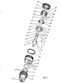
- the drill chucks shown in the drawing have an adapter shaft 1, the free end 1a of which is designed to be received in a tool holder 2 of a hammer drill, which is not shown in FIGS. 1 and 5, and is otherwise not shown.
- the adapter shaft 1 has two longitudinal grooves 1.1 closed at both ends, diametrically opposite one another, and offset by 90 ° from these two likewise diametrically opposite longitudinal grooves 1.2 open towards the end of the adapter shaft 1a.
- the latter longitudinal grooves 1.2 are used in the tool holder 2 for rotationally driving the adapter shaft 1, while the longitudinal grooves 1.1, which are closed at both ends, enable the adapter shaft in the tool holder to have an axial play limited by the two ends of the longitudinal grooves 1.1.
- Carriers or radially adjustable locking members of the tool holder 2 engage in the longitudinal grooves 1.1, 1.2, but this is known in detail and therefore requires no further description.
- the adapter shaft 1 is rotatably and with axial displacement play also held in the drill chuck, which is achieved in the exemplary embodiments in that coupling members 4 are provided in a chuck body receiving the adapter shaft 1, which are axially longer than the coupling members 4, also axially in a collar 5 of the adapter shaft 1 grasping nuts 6 and, despite the axial displacement play, bring about the rotational connection between the chuck body 3 and the adapter shaft 1.
- the axial displacement play of the adapter shaft 1 in the chuck body 3 is limited in the drill chuck according to FIG. 1 on the one hand by an annular stop surface 7 of the chuck body 3 and on the other hand by a stop ring 8 for the collar 5 of the adapter shaft 1 embedded in the chuck body 3. 5, however, the coupling members 4 are held axially immovably in the chuck body 3, so that here the two axial ends of the grooves 6, the axial movement of the adapter sheep Limit tes 1.
- the chuck body 3 has an axial passage 9, through which the impact action of the adapter shaft 1 can be transferred to the end of a drill, not shown in the drawing, which is held in the chuck between centrally adjustable chuck jaws 10.
- the chuck jaws 10 are guided obliquely to the chuck axis in the chuck body 3 and have a toothing 11 which engages in an internal thread of a clamping ring 12 which is rotatably and axially immovably mounted on the chuck body 3.
- This clamping ring 12 consists of two ring halves which are connected to one another by a clamping sleeve 13.
- a chuck key 14 can be attached to the chuck body 3 and engages with a toothed pinion 15 in a ring gear 16 of the clamping ring 12.
- the drill is guided axially displaceably between the chuck jaws 10.
- the chuck jaws 10 are equipped with hard metal inserts 17 on their clamping surfaces.
- a locking sleeve 19 is provided on the chuck body 3 that is non-rotatable, but axially displaceable against the pressure of a spring 18, which on its the clamping ring 12 facing edge has a toothing 20 which engages under the pressure of the spring 18 in a counter-toothing of the clamping ring 12, whereby the clamping ring 12 and the locking sleeve 19 are connected to each other in the tooth engagement.
- this detent seat cannot prevent an intentional turning of the clamping ring 12 by hand or with the aid of the clamping key 14, since in this case the locking sleeve 19 is temporarily pressed out of the toothing engagement against the force of the spring 18 via the tooth flanks which are inclined to it.
- the locking sleeve 19 is secured against rotation by means of lugs 21 which are formed on bolts 22 which are inserted radially into bores of the chuck body 3.
- two stop pieces 23 are provided for each nose 21, which do not impede the axial adjustment of the locking sleeve 19.
- a stop piece 24 is guided on the chuck, which is axially adjustable beyond the end of the chuck on the side of the adapter shaft 1 and in this direction is non-positively and positively clamped against the tool holder 2 of the hammer drill.
- This latter position of the stop piece 24 is in FIGS. 1 and 5 each because shown at 24 '. Otherwise, both figures show the position of the stop piece 24 completely retracted into the drill chuck.
- the stop piece 24 is arranged axially displaceable and non-rotatable with respect to the chuck body 3.
- the stop piece 24 consists of an annular plate 27 surrounding the adapter shaft 1 and of it on the side facing away from the tool holder 2 axially projecting guide webs 28, which carry the external thread 25 and are displaceable in guide recesses 29, which extend axially along the chuck body 3 and in the circumferential direction between the chuck jaws 10.
- These guide recesses 29 are formed by guide grooves, from which the external thread 25 of the guide webs 28 protrudes radially outward to such an extent that it can engage in the ring nut 26, which in turn is mounted in the circumferential direction between the guide recesses 29.
- the guide recesses 29 are formed directly in the chuck body 3.
- the ring nut 26 is mounted on the chuck body 3 between the guide recesses 29.
- the chuck body 3 is provided in the areas between the guide recesses 29 with a radially outwardly directed annular web 30, which engages in an annular groove 31 on the inside the ring nut 26 engages and thereby secures it against axial displacements.
- FIG. 1 In the exemplary embodiment according to FIG.
- opposing ring grooves are also provided in the chuck body 3, into which a spring ring 32 engages, which in the region of the guide webs 28 has a recess required for receiving the external thread 25 of the guide webs 28.
- the chuck body 3 carries an axially immovable and non-rotatable chuck sleeve 33 in which the guide recesses 29 are formed and with the aid of which the ring nut 26 is mounted.
- the guide webs 28 are formed con axially parallel sections of a cylindrical wall with the casing sleeve 33, so that they are aligned with the outer surface of the casing sleeve 33 in the guide recesses 29.
- the chuck sleeve 33 On the side facing the chuck jaws 10 and in the circumferential direction between the guide recesses 29, the chuck sleeve 33 is provided with cutouts 34 for the chuck jaws 10 so that the chuck sleeve 33 cannot hinder the adjustment of the chuck jaws 10.
- the chuck sleeve 33 will usually be made as an injection molded part made of plastic. Then, however, their surface hardness is not sufficient to form the radial shoulder required for the coupling members 4. Therefore, in the chuck sleeve 33 on the side facing away from the chuck jaws 10 a steel ring 35 which leaves the guide recesses 29 in place and which is continuously aligned on the inside with the casing sleeve 33 and forms the stop for the coupling members 4.
- the steel ring has on its outer edge between the guide recesses 29 radially outwardly angled and protruding tabs 36 which engage in the annular groove 31 provided on the inside of the ring nut 26 and secure the ring nut 26 against axial displacements.
- the tabs 36 are arranged side by side in pairs in the circumferential direction and each form a gap 37 between them, into which a cam 38 located on the casing sleeve 33 engages, so that as a result the steel ring 35 is held non-rotatably on the casing sleeve 33.
- the chuck sleeve 33 On its edge facing the chuck jaws 10, the chuck sleeve 33 has receptacles 39 for the lugs 21, which thus not only secure the locking sleeve 19 but also the chuck sleeve 33 against rotation.
- the axial displacement protection of the casing sleeve 33 is achieved on the one hand by an annular collar 40 on the casing body 3, and on the other hand by a spring ring 41 inserted into a groove of the casing body 3, on which the edges of the casing sleeve 33 and the steel ring 35 are axially supported.
- the drill chuck is axially pushed away from the tool holder 2 until the adapter shaft 1 engages both in the drill chuck and in the tool holder 2 at the corresponding stops, each limiting its axial play there, which is equivalent to the fact that the The adapter shaft 1 is pulled out of the tool holder 2 or the drill chuck at a maximum.
- the adapter shaft 1 is also brought in the tool holder 2 from the striking area of the striker, so that no strikes can be exerted on the adapter shaft 1 in this operating state even if due to incorrect operation of the hammer drill, the striking mechanism has not been switched off and the striker should continue to make its hammer movements.
Landscapes
- Engineering & Computer Science (AREA)
- Mechanical Engineering (AREA)
- Gripping On Spindles (AREA)
- Percussive Tools And Related Accessories (AREA)
Applications Claiming Priority (2)
| Application Number | Priority Date | Filing Date | Title |
|---|---|---|---|
| DE3639812A DE3639812C1 (de) | 1986-11-21 | 1986-11-21 | Bohrfutter mit einem zur Aufnahme im Werkzeughalter einer Hammerbohrmaschine ausgebildeten Adapterschaft |
| DE3639812 | 1986-11-21 |
Publications (3)
| Publication Number | Publication Date |
|---|---|
| EP0268758A2 true EP0268758A2 (fr) | 1988-06-01 |
| EP0268758A3 EP0268758A3 (en) | 1989-05-24 |
| EP0268758B1 EP0268758B1 (fr) | 1991-05-08 |
Family
ID=6314464
Family Applications (1)
| Application Number | Title | Priority Date | Filing Date |
|---|---|---|---|
| EP87112787A Expired - Lifetime EP0268758B1 (fr) | 1986-11-21 | 1987-09-02 | Mandrin à forer |
Country Status (5)
| Country | Link |
|---|---|
| US (1) | US4844482A (fr) |
| EP (1) | EP0268758B1 (fr) |
| JP (1) | JPS63139603A (fr) |
| DE (1) | DE3639812C1 (fr) |
| ES (1) | ES2021656B3 (fr) |
Families Citing this family (18)
| Publication number | Priority date | Publication date | Assignee | Title |
|---|---|---|---|---|
| DE4023304C1 (fr) * | 1990-07-21 | 1991-09-12 | Guenter Horst 7927 Sontheim De Roehm | |
| US5180175A (en) * | 1991-02-22 | 1993-01-19 | Mike Doolittle | Drill chuck key |
| GB2310391A (en) * | 1996-02-22 | 1997-08-27 | Boart Longyear Ltd | A shank adapter |
| US6073939A (en) * | 1998-06-05 | 2000-06-13 | Power Tool Holders Incorporated | Locking chuck |
| US6196554B1 (en) | 1998-12-15 | 2001-03-06 | Power Tool Holders Incorporated | Locking chuck |
| JP4616576B2 (ja) * | 2004-04-20 | 2011-01-19 | ユキワ精工株式会社 | チャック装置 |
| US20060237205A1 (en) * | 2005-04-21 | 2006-10-26 | Eastway Fair Company Limited | Mode selector mechanism for an impact driver |
| FR2886183B1 (fr) * | 2005-05-27 | 2007-07-13 | Amyot Sa Sa Ets | Mandrin porte-outil pour l'equipement d'une machine tournante, notamment du type "cle a choc" |
| US7806636B2 (en) * | 2005-08-31 | 2010-10-05 | Black & Decker Inc. | Dead spindle chucking system with sliding sleeve |
| US7455303B2 (en) * | 2005-09-02 | 2008-11-25 | The Jacobs Chuck Manufacturing Company | Chuck with internal nut |
| DE102005058657A1 (de) * | 2005-12-07 | 2007-06-14 | Röhm Gmbh | Bohrfutter |
| US20090200758A1 (en) * | 2008-02-07 | 2009-08-13 | Chin Hung Lam | Auto Locking Chuck |
| US8403339B2 (en) | 2008-06-18 | 2013-03-26 | Jacobs Chuck Manufacturing Company | Self tightening chuck with an axial lock |
| US8376371B2 (en) * | 2008-09-17 | 2013-02-19 | Jacobs Chuck Manufacturing Company | Locking chuck jaws |
| US8777232B2 (en) * | 2009-07-29 | 2014-07-15 | Jacobs Chuck Manufacturing Company | Self-tightening chuck with a radial lock |
| US8246477B2 (en) | 2010-05-20 | 2012-08-21 | Moyno, Inc. | Gear joint with super finished surfaces |
| US9352397B2 (en) | 2012-04-10 | 2016-05-31 | Apex Brands, Inc. | Locking chuck |
| US10556276B2 (en) | 2013-03-14 | 2020-02-11 | Apex Brands, Inc. | Locking chuck |
Family Cites Families (7)
| Publication number | Priority date | Publication date | Assignee | Title |
|---|---|---|---|---|
| US2016829A (en) * | 1934-11-06 | 1935-10-08 | Firm Kapital & Industriewerte | Modification of the electrically driven percussion drill |
| GB1195505A (en) * | 1967-07-31 | 1970-06-17 | Hilti Ag | Hammer Drill |
| DE2842783A1 (de) * | 1978-09-30 | 1980-04-10 | Bosch Gmbh Robert | Futter fuer handwerkzeugmaschinen, insbesondere bohr- und/oder schlaghaemmer |
| DE3125454A1 (de) * | 1981-06-29 | 1983-01-20 | Hilti AG, 9494 Schaan | Bohrhammer fuer bohr- und schlagbohrbetrieb |
| DE3241528C2 (de) * | 1982-11-10 | 1986-04-10 | Eugen Lutz GmbH u. Co Maschinenfabrik, 7130 Mühlacker | Werkzeugspannfutter für einen Bohrhammer |
| DE3413581C2 (de) * | 1984-04-11 | 1986-08-14 | Günter Horst 7927 Sontheim Röhm | Bohrfutter |
| DE3422195C2 (de) * | 1984-06-15 | 1987-04-09 | Günter Horst 7927 Sontheim Röhm | Schlagbohreinrichtung |
-
1986
- 1986-11-21 DE DE3639812A patent/DE3639812C1/de not_active Expired
-
1987
- 1987-09-02 EP EP87112787A patent/EP0268758B1/fr not_active Expired - Lifetime
- 1987-09-02 ES ES87112787T patent/ES2021656B3/es not_active Expired - Lifetime
- 1987-11-20 JP JP62294990A patent/JPS63139603A/ja active Pending
- 1987-11-23 US US07/124,310 patent/US4844482A/en not_active Expired - Fee Related
Also Published As
| Publication number | Publication date |
|---|---|
| JPS63139603A (ja) | 1988-06-11 |
| DE3639812C1 (de) | 1988-01-14 |
| EP0268758A3 (en) | 1989-05-24 |
| US4844482A (en) | 1989-07-04 |
| ES2021656B3 (es) | 1991-11-16 |
| EP0268758B1 (fr) | 1991-05-08 |
Similar Documents
| Publication | Publication Date | Title |
|---|---|---|
| EP0268758B1 (fr) | Mandrin à forer | |
| DE2842783C2 (fr) | ||
| DE3241528C2 (de) | Werkzeugspannfutter für einen Bohrhammer | |
| DE4343013C2 (de) | Bohrhammer mit einer Kombinations-Werkzeughalterung | |
| EP1504836B1 (fr) | Mandrin à changement rapide | |
| DE3414300C2 (fr) | ||
| DE3416964C2 (de) | Spannfutter für ein Werkzeug, insbes. zum Schlagbohren | |
| DE3406668A1 (de) | Bohrfutter zum schlagbohren | |
| EP0142611A1 (fr) | Outil de perçage pour usiner des surfaces de détalonnage dans des perçages préfabriqués | |
| DE19907331A1 (de) | Bohrfutter | |
| EP0762948B1 (fr) | Porte-outil pour perceuse manuelle, notamment pour marteau-foreur | |
| EP0253761A2 (fr) | Mandrin pour outils | |
| CH663919A5 (de) | Bohrfutter fuer ein werkzeug zum schlagbohren. | |
| DE3416986C2 (de) | Bohrfutter zum Schlagbohren | |
| EP0739267A1 (fr) | Dispositif d'entrainement en rotation d'outils pour machines-outils manuelles | |
| EP1572403A1 (fr) | Mandrin de serrage et tige de serrage destinee a celui-ci | |
| EP0194426B1 (fr) | Mandrin pour forage rotatif ou à percussion rotative | |
| DE3005459A1 (de) | Spannfutter fuer drehmaschinen | |
| EP0175065B1 (fr) | Mandrin réglable | |
| EP0005458B1 (fr) | Mandrin de serrage pour machines à tourner | |
| DE3424679C2 (fr) | ||
| DE3540223C2 (fr) | ||
| DE3409494C2 (de) | Werkzeugaufnahme für eine elektropneumatisch arbeitende Hammerbohrmaschine | |
| CH655875A5 (de) | Spannfutter, insbesondere fuer schlagbohrwerkzeuge. | |
| DE3315661A1 (de) | Spannfutter fuer ein werkzeug zum schlagbohren |
Legal Events
| Date | Code | Title | Description |
|---|---|---|---|
| PUAI | Public reference made under article 153(3) epc to a published international application that has entered the european phase |
Free format text: ORIGINAL CODE: 0009012 |
|
| AK | Designated contracting states |
Kind code of ref document: A2 Designated state(s): CH ES FR GB IT LI |
|
| PUAL | Search report despatched |
Free format text: ORIGINAL CODE: 0009013 |
|
| RHK1 | Main classification (correction) |
Ipc: B23B 31/04 |
|
| AK | Designated contracting states |
Kind code of ref document: A3 Designated state(s): CH ES FR GB IT LI |
|
| 17P | Request for examination filed |
Effective date: 19890413 |
|
| 17Q | First examination report despatched |
Effective date: 19900925 |
|
| GRAA | (expected) grant |
Free format text: ORIGINAL CODE: 0009210 |
|
| AK | Designated contracting states |
Kind code of ref document: B1 Designated state(s): CH ES FR GB IT LI |
|
| ITF | It: translation for a ep patent filed | ||
| ET | Fr: translation filed | ||
| GBT | Gb: translation of ep patent filed (gb section 77(6)(a)/1977) | ||
| PLBE | No opposition filed within time limit |
Free format text: ORIGINAL CODE: 0009261 |
|
| STAA | Information on the status of an ep patent application or granted ep patent |
Free format text: STATUS: NO OPPOSITION FILED WITHIN TIME LIMIT |
|
| 26N | No opposition filed | ||
| PGFP | Annual fee paid to national office [announced via postgrant information from national office to epo] |
Ref country code: FR Payment date: 19930705 Year of fee payment: 7 |
|
| PGFP | Annual fee paid to national office [announced via postgrant information from national office to epo] |
Ref country code: ES Payment date: 19930712 Year of fee payment: 7 |
|
| PGFP | Annual fee paid to national office [announced via postgrant information from national office to epo] |
Ref country code: CH Payment date: 19930721 Year of fee payment: 7 |
|
| PGFP | Annual fee paid to national office [announced via postgrant information from national office to epo] |
Ref country code: GB Payment date: 19930823 Year of fee payment: 7 |
|
| PG25 | Lapsed in a contracting state [announced via postgrant information from national office to epo] |
Ref country code: GB Effective date: 19940902 |
|
| PG25 | Lapsed in a contracting state [announced via postgrant information from national office to epo] |
Ref country code: ES Free format text: LAPSE BECAUSE OF EXPIRATION OF PROTECTION Effective date: 19940903 |
|
| PG25 | Lapsed in a contracting state [announced via postgrant information from national office to epo] |
Ref country code: LI Effective date: 19940930 Ref country code: CH Effective date: 19940930 |
|
| GBPC | Gb: european patent ceased through non-payment of renewal fee |
Effective date: 19940902 |
|
| PG25 | Lapsed in a contracting state [announced via postgrant information from national office to epo] |
Ref country code: FR Effective date: 19950531 |
|
| REG | Reference to a national code |
Ref country code: CH Ref legal event code: PL |
|
| REG | Reference to a national code |
Ref country code: FR Ref legal event code: ST |
|
| REG | Reference to a national code |
Ref country code: ES Ref legal event code: FD2A Effective date: 19990601 |
|
| PG25 | Lapsed in a contracting state [announced via postgrant information from national office to epo] |
Ref country code: IT Free format text: LAPSE BECAUSE OF NON-PAYMENT OF DUE FEES;WARNING: LAPSES OF ITALIAN PATENTS WITH EFFECTIVE DATE BEFORE 2007 MAY HAVE OCCURRED AT ANY TIME BEFORE 2007. THE CORRECT EFFECTIVE DATE MAY BE DIFFERENT FROM THE ONE RECORDED. Effective date: 20050902 |