EP0268976A2 - Cuve de filtre pour métaux liquides - Google Patents
Cuve de filtre pour métaux liquides Download PDFInfo
- Publication number
- EP0268976A2 EP0268976A2 EP87116930A EP87116930A EP0268976A2 EP 0268976 A2 EP0268976 A2 EP 0268976A2 EP 87116930 A EP87116930 A EP 87116930A EP 87116930 A EP87116930 A EP 87116930A EP 0268976 A2 EP0268976 A2 EP 0268976A2
- Authority
- EP
- European Patent Office
- Prior art keywords
- filter
- trough
- plate
- filter plate
- plates
- Prior art date
- Legal status (The legal status is an assumption and is not a legal conclusion. Google has not performed a legal analysis and makes no representation as to the accuracy of the status listed.)
- Withdrawn
Links
Images
Classifications
-
- C—CHEMISTRY; METALLURGY
- C22—METALLURGY; FERROUS OR NON-FERROUS ALLOYS; TREATMENT OF ALLOYS OR NON-FERROUS METALS
- C22B—PRODUCTION AND REFINING OF METALS; PRETREATMENT OF RAW MATERIALS
- C22B9/00—General processes of refining or remelting of metals; Apparatus for electroslag or arc remelting of metals
- C22B9/02—Refining by liquating, filtering, centrifuging, distilling, or supersonic wave action including acoustic waves
- C22B9/023—By filtering
-
- B—PERFORMING OPERATIONS; TRANSPORTING
- B22—CASTING; POWDER METALLURGY
- B22D—CASTING OF METALS; CASTING OF OTHER SUBSTANCES BY THE SAME PROCESSES OR DEVICES
- B22D43/00—Mechanical cleaning, e.g. skimming of molten metals
- B22D43/001—Retaining slag during pouring molten metal
- B22D43/004—Retaining slag during pouring molten metal by using filtering means
-
- Y—GENERAL TAGGING OF NEW TECHNOLOGICAL DEVELOPMENTS; GENERAL TAGGING OF CROSS-SECTIONAL TECHNOLOGIES SPANNING OVER SEVERAL SECTIONS OF THE IPC; TECHNICAL SUBJECTS COVERED BY FORMER USPC CROSS-REFERENCE ART COLLECTIONS [XRACs] AND DIGESTS
- Y02—TECHNOLOGIES OR APPLICATIONS FOR MITIGATION OR ADAPTATION AGAINST CLIMATE CHANGE
- Y02P—CLIMATE CHANGE MITIGATION TECHNOLOGIES IN THE PRODUCTION OR PROCESSING OF GOODS
- Y02P10/00—Technologies related to metal processing
- Y02P10/20—Recycling
Definitions
- the invention relates to a filter trough for liquid metals with at least one filter plate which is arranged interchangeably in a trough made of refractory material.
- a filter plate made of ceramic foam lies in a shape-matched opening at the bottom of the filter trough.
- the plate is conical at the edge and the edges of the opening are adapted accordingly. The filter plate can then only penetrate into the opening to a certain depth and is held in an easily detachable manner in this way.
- the filter plate can only be changed when the operation is interrupted.
- the filter requires a relatively large amount of space, which is often not available in the direction of production.
- the size of the filter plate is fixed by the size of the opening.
- the invention has for its object to provide an improved filter of the type mentioned, which allows adaptation of the filter size, takes up little space and opens up the possibility of changing filter plates without interrupting operation. In addition, oxides and other contaminants floating on the surface should be safely retained.
- the invention is based on the filter trough described at the outset and is characterized in that the filter plate is inserted approximately vertically into edge grooves of the trough and that on the inlet side in front of the filter plate there is a refractory Material existing siphon plate sits approximately vertically in the groove of the trough and ends with its lower edge at a distance from the trough bottom.
- the filter trough Due to the vertical position of the filter plate, the filter trough can be kept very short and therefore takes up little space in the direction of production.
- the filter plate is also accessible during operation and can be replaced.
- the siphon plate keeps contaminants floating on the surface in front of the filter plate.
- two filter plates can be inserted approximately vertically into edge grooves of the trough at a distance from one another. Then it is possible to change a filter plate in continuous operation while maintaining the filter effect of the other plate. If necessary, three or more filter plates can also be arranged one behind the other. Ceramic foam known per se is preferably used as the material for the filter plates. It can be provided that the porosity, measured in the form of the number of pores per unit length, is approximately the same for the two filter plates.
- the front filter plate in the flow direction can consist of a larger-pored ceramic foam than the rear filter plate. The front plate then filters out the coarser impurities and the downstream plate ensures fine filtering.
- the front filter plate can have a smaller cross section than the rear filter plate. This can easily be achieved in a further development of the invention in that the height of the front filter plate is less than that of the rear filter plate and that a closure plate is arranged in the peripheral grooves under the front filter plate, such that the upper edge of the front and rear filter plates is approximately in same height.
- the drain is advantageously formed by a recess on the upper edge of a supporting wall. If filter plates with a relatively small cross-section are sufficient for a certain application, the height of the filter plates can be reduced in a simple manner. The bottom of the drain must then be lowered so that it lies at the level below the upper edge of the filter plates. However, a closure plate can also be inserted under the filter plates in the edge grooves in order to keep the upper edge of the filter plates at the same height.
- a closable floor drain in the inlet chamber containing the siphon plate To empty the filter trough, it is possible to provide a closable floor drain in the inlet chamber containing the siphon plate.
- a sealing tape made of a refractory material that expands under the action of heat is expediently provided.
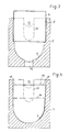
- the bottom of the trough can be flat or, according to a recommendation of the invention, have the shape of a circular cylinder, the axis of which extends transversely to the main surface of the filter plate or plates.
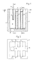
- the filter trough 1 shown in the figures consists of refractory material and has the outer shape of a cuboid. The interior is also cuboid in the upper area and changes in the direction of the floor 2 into a circular cylindrical shape.
- a siphon plate 7 made of refractory material is inserted into edge grooves 8 from above. Liquid metal which is introduced into the chamber 6 in front of the siphon plate 7 must then run around the lower edge of the plate 7 before it can pass through the first filter plate 9 made of ceramic foam.
- the plate 9, like the further filter plate 10, is inserted into edge grooves 11 of the filter trough 1.
- a sealing tape (not shown) of a known type is used for sealing on the floor and in the area of the edge grooves, which expands under the influence of heat and thus ensures a secure seal.
- the filtered metal can leave the filter trough 1 through a recess 12 at the upper edge.
- a bore 13 in the bottom of the chamber 6 which is closed during operation by a stopper (not shown) enables the filter trough to be emptied.
- the filter plates 9, 10 are accessible from above during operation. It is therefore possible to replace the two filter plates 9, 10 one after the other without interrupting operation.
- the exchange is made easier by the slightly conical design of the edge grooves 11 (see FIG. 2). The same applies to the siphon plate with its edge groove 8.
- a dash-dotted line 14 shows that a filter plate of lower height can also be used, the upper edge of which coincides with the knitting-dotted line 14.
- the recess 12 is then, as indicated by a further dash-dotted line 15, to be adjusted in depth accordingly.
Landscapes
- Engineering & Computer Science (AREA)
- Mechanical Engineering (AREA)
- Chemical & Material Sciences (AREA)
- Physics & Mathematics (AREA)
- Acoustics & Sound (AREA)
- Manufacturing & Machinery (AREA)
- Materials Engineering (AREA)
- Metallurgy (AREA)
- Organic Chemistry (AREA)
- Manufacture And Refinement Of Metals (AREA)
- Filtering Of Dispersed Particles In Gases (AREA)
- Filtering Materials (AREA)
Applications Claiming Priority (2)
| Application Number | Priority Date | Filing Date | Title |
|---|---|---|---|
| DE8631322U | 1986-11-22 | ||
| DE8631322U DE8631322U1 (de) | 1986-11-22 | 1986-11-22 | Filtertrog für Flüssigmetalle |
Publications (2)
| Publication Number | Publication Date |
|---|---|
| EP0268976A2 true EP0268976A2 (fr) | 1988-06-01 |
| EP0268976A3 EP0268976A3 (fr) | 1990-05-30 |
Family
ID=6800457
Family Applications (1)
| Application Number | Title | Priority Date | Filing Date |
|---|---|---|---|
| EP87116930A Withdrawn EP0268976A3 (fr) | 1986-11-22 | 1987-11-17 | Cuve de filtre pour métaux liquides |
Country Status (2)
| Country | Link |
|---|---|
| EP (1) | EP0268976A3 (fr) |
| DE (1) | DE8631322U1 (fr) |
Cited By (3)
| Publication number | Priority date | Publication date | Assignee | Title |
|---|---|---|---|---|
| WO1992002649A1 (fr) * | 1990-08-03 | 1992-02-20 | Alcan International Limited | Filtre pour metal liquide |
| EP0490371A3 (en) * | 1990-12-13 | 1993-10-06 | Aluminum Company Of America | Multistage rigid media filter for molten metal |
| CN106825485A (zh) * | 2016-12-29 | 2017-06-13 | 江苏中翼汽车新材料科技有限公司 | 一种合金液净化用虹吸转移管 |
Family Cites Families (4)
| Publication number | Priority date | Publication date | Assignee | Title |
|---|---|---|---|---|
| US4154689A (en) * | 1976-09-30 | 1979-05-15 | Swiss Aluminium Ltd. | Filtering and inline degassing of molten metal |
| US4092153A (en) * | 1977-07-29 | 1978-05-30 | Swiss Aluminium Limited | Filtering and inline degassing of molten metal |
| US4277281A (en) * | 1979-08-16 | 1981-07-07 | Southwire Company | Continuous filter for molten copper |
| US4640497A (en) * | 1985-10-25 | 1987-02-03 | Swiss Aluminium Ltd. | Filtration apparatus |
-
1986
- 1986-11-22 DE DE8631322U patent/DE8631322U1/de not_active Expired
-
1987
- 1987-11-17 EP EP87116930A patent/EP0268976A3/fr not_active Withdrawn
Cited By (4)
| Publication number | Priority date | Publication date | Assignee | Title |
|---|---|---|---|---|
| WO1992002649A1 (fr) * | 1990-08-03 | 1992-02-20 | Alcan International Limited | Filtre pour metal liquide |
| EP0490371A3 (en) * | 1990-12-13 | 1993-10-06 | Aluminum Company Of America | Multistage rigid media filter for molten metal |
| CN106825485A (zh) * | 2016-12-29 | 2017-06-13 | 江苏中翼汽车新材料科技有限公司 | 一种合金液净化用虹吸转移管 |
| CN106825485B (zh) * | 2016-12-29 | 2018-08-21 | 江苏中翼汽车新材料科技有限公司 | 一种合金液净化用虹吸转移管 |
Also Published As
| Publication number | Publication date |
|---|---|
| EP0268976A3 (fr) | 1990-05-30 |
| DE8631322U1 (de) | 1987-01-15 |
Similar Documents
| Publication | Publication Date | Title |
|---|---|---|
| DE2920978C2 (de) | Vorrichtung zur anaeroben Abwasserreinigung | |
| DE4337384C2 (de) | Probeneinsatz zur Bildung keilförmiger Probenschächte für ultradünne Plattengele in der Elektrophorese | |
| DE2030617C3 (de) | Schrägklärer | |
| DE923365C (de) | Gas- und Fluessigkeits-Kontaktapparat | |
| DE1947564A1 (de) | Vorrichtung zum Separieren von in Fluessigkeit susperndiertem Material | |
| DE2250873B2 (de) | Lamellenseparator für Schlämmtanks | |
| EP2183409B1 (fr) | Procédé pour faire fonctionner des cellules électrolytiques au cuivre | |
| DE2823182C2 (de) | Käseform aus Kunststoff | |
| DD252204A5 (de) | Vorrichtung zum filtrieren von schmelzfluessigem metall | |
| AT400935B (de) | Tauchgiessrohr | |
| EP0390742A1 (fr) | Dispositif et procédé de filtration de bains de métal fondu | |
| DE3889187T2 (de) | Unlösliche Elektrode. | |
| DE899711C (de) | Verfahren und Vorrichtung zur Verhinderung des Verspritzens des Elektrolyts durch aus diesem eintweichendes Gas bei Schmelzflusselektrolysen | |
| DE69511772T2 (de) | Zufuhrvorrichtung für einen Scheibenfilter | |
| DE2441667C3 (de) | Absetzbehälter mit geneigten Lamellen zum Abscheiden von Feststoffen aus einer Flüssigkeit | |
| DE2558377C2 (de) | Probeentnahmegerät | |
| DE8631322U1 (de) | Filtertrog für Flüssigmetalle | |
| EP0522265B1 (fr) | Séparateur de liquide | |
| DE2849333C3 (de) | Keramische Probenahmevorrichtung für Metallschmelzen insbesondere Stahlschmelzen | |
| DE3114222C2 (de) | Vorrichtung zum Chloren geschmolzener Magnesiumchlorsalze | |
| EP0040257B1 (fr) | Tuyau de drainage à section transversale triangulaire | |
| DE2125633B2 (de) | Schraegklaerer | |
| DE9018117U1 (de) | Mehrere Abscheideabteilungen aufweisender Leichtflüssigkeitsabscheider | |
| DE902131C (de) | Waschband fuer Filter aller Art | |
| DE465881C (de) | Filter fuer kohlensaeurehaltige Fluessigkeiten |
Legal Events
| Date | Code | Title | Description |
|---|---|---|---|
| PUAI | Public reference made under article 153(3) epc to a published international application that has entered the european phase |
Free format text: ORIGINAL CODE: 0009012 |
|
| AK | Designated contracting states |
Kind code of ref document: A2 Designated state(s): CH DE GB LI |
|
| PUAL | Search report despatched |
Free format text: ORIGINAL CODE: 0009013 |
|
| AK | Designated contracting states |
Kind code of ref document: A3 Designated state(s): CH DE GB LI |
|
| RHK1 | Main classification (correction) |
Ipc: C22B 9/02 |
|
| 17P | Request for examination filed |
Effective date: 19901031 |
|
| 17Q | First examination report despatched |
Effective date: 19910723 |
|
| STAA | Information on the status of an ep patent application or granted ep patent |
Free format text: STATUS: THE APPLICATION IS DEEMED TO BE WITHDRAWN |
|
| 18D | Application deemed to be withdrawn |
Effective date: 19920204 |