EP0268991A2 - Dispositif de fabrication de mélanges prêts à l'emploi à partir des marchandises en vrac chargées dans un silo - Google Patents
Dispositif de fabrication de mélanges prêts à l'emploi à partir des marchandises en vrac chargées dans un silo Download PDFInfo
- Publication number
- EP0268991A2 EP0268991A2 EP87117023A EP87117023A EP0268991A2 EP 0268991 A2 EP0268991 A2 EP 0268991A2 EP 87117023 A EP87117023 A EP 87117023A EP 87117023 A EP87117023 A EP 87117023A EP 0268991 A2 EP0268991 A2 EP 0268991A2
- Authority
- EP
- European Patent Office
- Prior art keywords
- outlet
- silo
- mixing
- shaft
- mixing device
- Prior art date
- Legal status (The legal status is an assumption and is not a legal conclusion. Google has not performed a legal analysis and makes no representation as to the accuracy of the status listed.)
- Granted
Links
- 239000000203 mixture Substances 0.000 title claims abstract description 13
- 238000002156 mixing Methods 0.000 claims abstract description 58
- 230000001413 cellular effect Effects 0.000 claims abstract description 20
- 239000013590 bulk material Substances 0.000 claims abstract description 17
- 239000004568 cement Substances 0.000 claims abstract description 6
- 239000004576 sand Substances 0.000 claims abstract description 6
- 238000004519 manufacturing process Methods 0.000 claims abstract description 4
- 238000007789 sealing Methods 0.000 claims description 12
- 238000010276 construction Methods 0.000 claims description 11
- 230000005540 biological transmission Effects 0.000 claims description 7
- 230000008878 coupling Effects 0.000 claims description 3
- 238000010168 coupling process Methods 0.000 claims description 3
- 238000005859 coupling reaction Methods 0.000 claims description 3
- 238000003756 stirring Methods 0.000 claims description 2
- 239000011449 brick Substances 0.000 claims 1
- 239000004570 mortar (masonry) Substances 0.000 description 5
- XLYOFNOQVPJJNP-UHFFFAOYSA-N water Substances O XLYOFNOQVPJJNP-UHFFFAOYSA-N 0.000 description 4
- 238000004140 cleaning Methods 0.000 description 2
- 238000009434 installation Methods 0.000 description 2
- 230000001680 brushing effect Effects 0.000 description 1
- 230000000694 effects Effects 0.000 description 1
- 238000011049 filling Methods 0.000 description 1
- 238000011010 flushing procedure Methods 0.000 description 1
- 238000011068 loading method Methods 0.000 description 1
- 239000002994 raw material Substances 0.000 description 1
Images


Classifications
-
- B—PERFORMING OPERATIONS; TRANSPORTING
- B28—WORKING CEMENT, CLAY, OR STONE
- B28C—PREPARING CLAY; PRODUCING MIXTURES CONTAINING CLAY OR CEMENTITIOUS MATERIAL, e.g. PLASTER
- B28C9/00—General arrangement or layout of plant
- B28C9/006—General arrangement or layout of plant comprising a multicompartment silo with the mixing device, e.g. a mixing screw, fitted directly at the underside of the silo, e.g. with proportioning means at the exit of the silo
Definitions
- the invention relates to a device for the production of ready-to-use mixtures from bulk material, such as e.g. Cement and sand.
- the invention has for its object to provide a device with which bulk goods can be removed from a silo directly and immediately after removal from the silo Allow ready-to-use mixtures to be processed.
- each silo outlet is equipped with a metering device for the metered discharge of bulk material and that a discharge opening of each metering device is connected to the associated input opening of a mixing device.
- the bulk material emerging from the silo outlet flows into the metering device in a continuous flow and is introduced in metered quantity into the mixing device immediately after leaving the metering device.
- cement and sand can be fed into the mixing device in the respective predetermined mixing ratio, from which, after appropriate mixing and addition of water, ready-to-use mortar emerges and is ready for further processing on the construction site.
- the device according to the invention for producing ready-to-use mixtures can be put into operation by simply switching on the metering device and the mixing device in order to continuously deliver ready-to-use mixtures.
- the arrangement of the dosing device in the immediate vicinity of the silo outlets in a multi-chamber silo enables a compact construction. Multi-chamber silos on construction sites can thus be used directly to produce ready-to-use mixtures. After installation of the filled multi-chamber silo on the construction site and installation of the The device is ready for corresponding connections of current for the drive motors of the metering devices and the mixing device and the supply of water to the mixing device.
- the metering device and the mixing device can remain connected to the construction site silo if the silo is picked up and transported away by a truck, for example for refilling. Immediately after the new construction site silo has been refilled, the device can be put back into operation in order to produce ready-to-use mixtures.
- the device is characterized in that the metering device is designed as an approximately horizontal rotary valve.
- the cellular wheel sluice comprises a wheel chamber which can be flanged in front of the outlet flange of the associated silo outlet and in which a cell wheel which can be rotated by means of a drive is arranged.
- a cellular wheel sluice can divide the flow of bulk material continuously emerging from the silo outlet into smaller subsets, each subset corresponding to the filling volume of one cell of the cellular wheel. Depending on the speed of rotation of the cellular wheel, a certain amount is therefore removed from the silo or fed to the mixing device in a certain time unit.
- a cellular wheel sluice is structurally simple and operates relatively reliably. The dosage is relatively accurate and can be changed by changing the speed of the Cell wheel can also be changed easily.
- the cellular wheel sluice advantageously forms a closure of the silo outlet at the same time, because the silo contents are only discharged when the cellular wheel rotates in the wheel chamber.
- the cellular wheel sluice can be connected to a silo outlet in a structurally very simple manner.
- the silo outlet has a flange to which the wheel chamber is flanged.
- a cover plate covering the wheel chamber except for an inlet area is inserted in the silo outlet.
- This cover plate can also be connected to the wheel chamber, so that the silo container itself remains essentially unchanged and only the cellular wheel sluice of the metering device is flanged together with the cover plate from the outside to the silo outlet.
- Each cell wheel consists of a central disc and star-shaped, upright flat bars. Two adjacent flat bars each delimit a cell, the edges of the upstanding flat bars brushing closely against the upper and lower walls of the wheel chamber when the cell wheel rotates. If a cell passes under the inlet area in the cover plate, bulk material that slides out of the silo outlet enters the cell and is carried along by the rotating cell wheel.
- each flat bar in the attachment area on the central disk runs obliquely against the direction of rotation and an outer in Section bent in the direction of rotation.
- the portions of the bulk material carried along by the cellular wheel can fall out of the wheel chamber again, since a lower closure plate of the wheel chamber has an outlet which is equipped with an outlet flange.
- the outlet flange serves to facilitate connection to the further devices connected downstream, such as the mixing device, which are designed as cellular wheel sluices.
- the bulk goods in the chambers of the construction site silo must be able to fall evenly out of the silo outlet so that a uniform loading of the metering devices designed as cellular wheel sluices is guaranteed. Forming bridges in the bulk material would interfere with the required smooth wake of the bulk material.
- at least one stirring finger protruding into the silo container is arranged on the central disk of each cell wheel. During the operation of the metering devices, the agitator fingers rotate with the cell wheel, so that bulk material that slides in the area of the silo outlet is loosened continuously and can enter the cell wheel sluice in a steady flow.
- the mixing device downstream of the metering devices has inlets which can be connected to the outlet flanges of the metering device by means of corresponding flanges.
- the connection with flanges is sufficiently firm, so that on special brackets for attaching the mixer device on the silo can be omitted.
- the mixing device preferably has an approximately horizontally hanging tube housing under the outlet flanges, in which a rotary shaft runs, the shaft being equipped with screw vanes in the sections corresponding to the inlets of the mixing device and in the adjoining section having approximately radially projecting mixing vanes.
- the screw vanes convey the bulk material quantities emerging from the outlets of the metering devices into the mixing area.
- the mixing blades cause intensive mixing. Here, e.g. then, if mortar mixtures are to be produced, the required water is also added.
- the finished mixture can emerge from the mixing device, since the tube housing has an end outlet at the front end, which corresponds to the section of the shaft with the mixing blades.
- each mixing blade consists of pairs of tabs projecting radially from the shaft side by side, which are each connected to one another at the free ends by a bridge tab.
- Each tab is set obliquely on the shaft with an angle of attack, so that during the revolutions of the shaft, the mixture to be produced is also conveyed in the longitudinal direction of the tube housing Mixing device takes place.
- each bridge plate is placed between the plates with an angle of inclination, which makes the mixing of the mixture components more intensive.
- the mixing blades are offset in the longitudinal direction of the shaft, which also contributes to improved mixing.
- the mixing device At its end facing away from the end outlet of the tubular housing, the mixing device has the drive motor with an associated gear for the shaft.
- the drive motor and transmission form a structural unit which is particularly advantageously hinged to a front end of the tubular housing. This makes cleaning the mixing device easier. After the unit formed from the drive motor and transmission has been folded down, the mixing device, in particular the tubular housing, can be sprayed out with water and thus easily cleaned.
- the shaft with the worm blades and the mixing blades can be inserted into the tubular housing and is non-positively connected to the transmission when the drive motor is folded onto the tubular housing, since the transmission has a plug-in coupling that can be brought into operative connection with the drive end of the shaft.
- the tubular housing has, with particular advantage, a removable end plate in which the associated end of the shaft is mounted. After removing the end shield, the shaft can be pulled out of the tube housing, which makes cleaning and flushing the tube housing and shaft easier.
- the transmission has a sealing flange on the output side and the tubular housing has an elastic sealing element at the end facing the sealing flange.
- the drive unit can be locked by means of appropriate tensioning elements, closures or the like after it has been folded onto the tube housing, so that the sealing flange presses against the elastic sealing element of the tube housing.
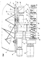
- FIG. 1 shows a construction site silo 1 in a schematic side view. It consists of an outer container 2 and an inner container 3 inserted therein. On the underside, the containers 2, 3 have outlets 4, 5, from which the in the container tern 2.3 stored bulk goods can leak. A metering device 6,7 is connected to the free ends of the outlets 4, 5. Each metering device has an outlet 8.9. Inlets 10, 11 of a mixing device are connected to the outlets 8, 9 and have a tube housing 13 in which the bulk material components dosed from the silo can be mixed by mechanically movable mixer elements located in the tube housing 13 via a gear 14 and motor 15 existing drive unit can be moved.
- FIG. 2 shows a schematic sectional view of the silo outlets 4, 5.
- Each silo outlet is equipped with an outlet flange 16, 17 at the free end.
- Each outlet flange serves to flange a metering device 6, 7 (FIG. 1) onto the respective silo outlet. Since the metering devices 6, 7 are of identical design, the structure and the mode of operation of the metering devices are described below using the exemplary embodiment of the metering device 7 assigned to the silo outlet 4, which is visible here on the right-hand side of the drawing.
- the metering device 7 of the silo outlet 4 consists of a cellular wheel sluice which comprises a wheel chamber 18 which can be flanged in front of the outlet flange 17 of the silo outlet 4 and in which a cellular wheel 19 is rotatably arranged.
- Each cellular wheel 19 consists of a central disc 22 and star-shaped, upright flat bars 23. In the area above the central disc, the cover plate 21 has the shape of a cone protruding into the silo outlet.
- a lower closure plate 25 of the wheel chamber 18 is equipped with a bearing 24 for the central disk 22, so that a shaft end 27 located on the driven side of a gear 26 which can be flanged under the closure plate 25 can rotate the central disk and thus the cellular wheel 19.
- an electric motor is provided for driving the cellular wheel.
- the closure plate 25 of the wheel chamber 18 has the outlet 9, which is equipped at the free end with an outlet flange.
- the inlet 11 of the mixing device 12 (FIG. 1) is placed with a corresponding flange on the outlet flange 29 of the outlet 9 of the metering device 7.
- the second outlet 5 of the silo is equipped with an identical metering device and is not described in detail here.
- the outlet 8 of this metering device of the outlet 5 is also connected to an inlet 10 of the mixing device 12.
- the tube housing of the mixing device is designated 13.
- a rotatably driven shaft runs in the tubular housing and is equipped with screw blades in the section corresponding to the inlets 10, 11 and mixing blades which project approximately radially in a subsequent section 32 has.
- the tubular housing has an end outlet 33.
- Each mixing paddle consists of pairs of tabs 34 which project radially from the shaft and which are connected to each other at the free ends by a bridge tab 35 aligned parallel to the longitudinal axis of the shaft. As shown in FIG. 2, each tab 34 is set at an angle on the shaft 30. Each bridge plate 35 is placed between the plates 34 at a certain angle of inclination. In addition, the mixing blades are offset in the longitudinal direction of the shaft.
- a drive motor 36 forms with its gear for the shaft a hinged unit hinged to one end of the tubular housing 13.
- the folding mechanism is not shown here, but can be designed as a simple hinge.
- the transmission On the output side, the transmission has a plug-in coupling which can be brought into operative connection with the drive-side end of the shaft 30.
- the gear 37 has a sealing flange 39 on the output side.
- the tubular housing 13 has at its end facing the sealing flange 39 an elastic sealing element 40 with which the sealing flange 39 of the gear comes into contact.
- FIG. 3 shows a plan view of a wheel chamber 18 of the metering device 7, which is open at the top, to clarify the design of the metering device 7.
- the side 41 of the cover plate 21, which delimits the inlet area into the metering device 7, is indicated by the dashed double line which is curved in the form of an arc.
- the central disk 22, which is seated on the shaft end 27, carries the star-shaped, upright, flat bars 23. Each flat bar is oriented obliquely in the attachment area on the central disk against the direction of rotation and has an outer section bent in the direction of rotation. These sections of the flat bars protruding under the central disk 22 delimit a cell with a constant volume.
- Each cell between two flat bars 23 passing the inlet area is filled with bulk material trailing out of the silo.
- the bulk material flow from the silo is continuously broken down into equal parts.
- the partial quantities fall successively into the outlet 9 and, as described above, reach the mixing device for further processing
Landscapes
- Preparation Of Clay, And Manufacture Of Mixtures Containing Clay Or Cement (AREA)
- Filling Or Emptying Of Bunkers, Hoppers, And Tanks (AREA)
- Processing And Handling Of Plastics And Other Materials For Molding In General (AREA)
- Apparatuses For Bulk Treatment Of Fruits And Vegetables And Apparatuses For Preparing Feeds (AREA)
Priority Applications (1)
| Application Number | Priority Date | Filing Date | Title |
|---|---|---|---|
| AT87117023T ATE61966T1 (de) | 1986-11-28 | 1987-11-19 | Vorrichtung zur herstellung gebrauchsfertiger mischungen aus in einem silo bereitgehaltenem schuettgut. |
Applications Claiming Priority (2)
| Application Number | Priority Date | Filing Date | Title |
|---|---|---|---|
| DE19863640766 DE3640766A1 (de) | 1986-11-28 | 1986-11-28 | Vorrichtung zur herstellung gebrauchsfertiger mischungen aus in einem silo bereitgehaltenem schuettgut |
| DE3640766 | 1986-11-28 |
Publications (3)
| Publication Number | Publication Date |
|---|---|
| EP0268991A2 true EP0268991A2 (fr) | 1988-06-01 |
| EP0268991A3 EP0268991A3 (en) | 1989-04-05 |
| EP0268991B1 EP0268991B1 (fr) | 1991-03-27 |
Family
ID=6315049
Family Applications (1)
| Application Number | Title | Priority Date | Filing Date |
|---|---|---|---|
| EP87117023A Expired - Lifetime EP0268991B1 (fr) | 1986-11-28 | 1987-11-19 | Dispositif de fabrication de mélanges prêts à l'emploi à partir des marchandises en vrac chargées dans un silo |
Country Status (3)
| Country | Link |
|---|---|
| EP (1) | EP0268991B1 (fr) |
| AT (1) | ATE61966T1 (fr) |
| DE (2) | DE3640766A1 (fr) |
Cited By (8)
| Publication number | Priority date | Publication date | Assignee | Title |
|---|---|---|---|---|
| EP0318874A1 (fr) * | 1987-12-04 | 1989-06-07 | Silo Estrich Gmbh + Co. Vertriebs Kg. | Dispositif pour la fabrication des mortiers, chapes ou similaires prêts à être employés |
| EP0374418A1 (fr) * | 1988-12-07 | 1990-06-27 | Maschinen- und Apparatebau August Tepe GmbH | Dispositif pour la fabrication de mélanges prêts à être utilisés à partir de matériaux un vrac par exemple du ciment et du sable |
| EP0478865A1 (fr) * | 1990-10-04 | 1992-04-08 | José Ramon Madera Iglesias | Installation portable pour doser et mélanger du béton sec en vrac et autres produits granulaire |
| US5624183A (en) * | 1993-03-29 | 1997-04-29 | Schuff; David A. | Apparatus for metering and mixing aggregate and cement |
| US5785420A (en) * | 1993-03-29 | 1998-07-28 | Schuff; David A. | Apparatus for metering and mixing aggregate and cement |
| IT202100010937A1 (it) * | 2021-04-29 | 2022-10-29 | Ziche Investimenti S R L | Sistema perfezionato per la produzione di materiali da costruzione |
| CN118287188A (zh) * | 2024-02-21 | 2024-07-05 | 天津水泥工业设计研究院有限公司 | 一种适宜于粉磨高细物料的均化布料稳料仓及工作方法 |
| CN118387483A (zh) * | 2024-05-17 | 2024-07-26 | 广东智子智能技术有限公司 | 粉体破拱下料装置 |
Families Citing this family (1)
| Publication number | Priority date | Publication date | Assignee | Title |
|---|---|---|---|---|
| DE4141068C2 (de) * | 1991-12-13 | 1996-02-01 | Masch Und Apparatebau A Tepe | Mobile Betonmischanlage |
Family Cites Families (10)
| Publication number | Priority date | Publication date | Assignee | Title |
|---|---|---|---|---|
| FR955060A (fr) * | 1950-01-07 | |||
| DE660006C (de) * | 1936-05-06 | 1938-05-14 | Anton Seelmann U Soehne G | Regelbare Zuteileinrichtung fuer Zement o. dgl. |
| BE495828A (fr) * | 1950-03-31 | |||
| CH339550A (de) * | 1956-03-19 | 1959-06-30 | Egli & Erbes | Betonaufbereitungsanlage |
| US3967815A (en) * | 1974-08-27 | 1976-07-06 | Backus James H | Dustless mixing apparatus and method for combining materials |
| DE3013280C2 (de) * | 1980-04-05 | 1983-11-17 | Mathis System-Technik Gmbh, 7801 Merdingen | Vorrichtung zur insbesondere kontinuierlichen Herstellung von angemachtem Mörtel o.dgl. |
| DE3031219C2 (de) * | 1980-05-27 | 1983-10-06 | Aliva AG, 8967 Widen, Mutschellen | Materialzuspeiser für Anlagen zum pneumatischen Fördern von Schüttgütern |
| US4427297A (en) * | 1982-04-16 | 1984-01-24 | Cemen-Tech, Inc. | Concrete ingredient metering device |
| DK156546C (da) * | 1982-04-30 | 1990-01-29 | Framix B V | Fremgangsmaade og apparat til fremstilling af moertel |
| LU85282A1 (fr) * | 1984-04-02 | 1985-11-27 | Jacques Gilson | Dispositif de malaxage et de dosage |
-
1986
- 1986-11-28 DE DE19863640766 patent/DE3640766A1/de active Granted
-
1987
- 1987-11-19 EP EP87117023A patent/EP0268991B1/fr not_active Expired - Lifetime
- 1987-11-19 DE DE8787117023T patent/DE3768916D1/de not_active Expired - Lifetime
- 1987-11-19 AT AT87117023T patent/ATE61966T1/de not_active IP Right Cessation
Cited By (9)
| Publication number | Priority date | Publication date | Assignee | Title |
|---|---|---|---|---|
| EP0318874A1 (fr) * | 1987-12-04 | 1989-06-07 | Silo Estrich Gmbh + Co. Vertriebs Kg. | Dispositif pour la fabrication des mortiers, chapes ou similaires prêts à être employés |
| EP0374418A1 (fr) * | 1988-12-07 | 1990-06-27 | Maschinen- und Apparatebau August Tepe GmbH | Dispositif pour la fabrication de mélanges prêts à être utilisés à partir de matériaux un vrac par exemple du ciment et du sable |
| EP0478865A1 (fr) * | 1990-10-04 | 1992-04-08 | José Ramon Madera Iglesias | Installation portable pour doser et mélanger du béton sec en vrac et autres produits granulaire |
| US5624183A (en) * | 1993-03-29 | 1997-04-29 | Schuff; David A. | Apparatus for metering and mixing aggregate and cement |
| US5785420A (en) * | 1993-03-29 | 1998-07-28 | Schuff; David A. | Apparatus for metering and mixing aggregate and cement |
| IT202100010937A1 (it) * | 2021-04-29 | 2022-10-29 | Ziche Investimenti S R L | Sistema perfezionato per la produzione di materiali da costruzione |
| EP4083884A1 (fr) * | 2021-04-29 | 2022-11-02 | Ziche Investimenti S.r.l. | Système amélioré pour la production de matériaux de construction |
| CN118287188A (zh) * | 2024-02-21 | 2024-07-05 | 天津水泥工业设计研究院有限公司 | 一种适宜于粉磨高细物料的均化布料稳料仓及工作方法 |
| CN118387483A (zh) * | 2024-05-17 | 2024-07-26 | 广东智子智能技术有限公司 | 粉体破拱下料装置 |
Also Published As
| Publication number | Publication date |
|---|---|
| DE3640766A1 (de) | 1988-06-01 |
| DE3768916D1 (de) | 1991-05-02 |
| EP0268991A3 (en) | 1989-04-05 |
| ATE61966T1 (de) | 1991-04-15 |
| EP0268991B1 (fr) | 1991-03-27 |
| DE3640766C2 (fr) | 1989-10-12 |
Similar Documents
| Publication | Publication Date | Title |
|---|---|---|
| DE69814786T2 (de) | Mischer | |
| DE3110437C2 (de) | Mischer | |
| DE2337129A1 (de) | Vorrichtung zum bereiten und abgeben von faser-beton-gemischen | |
| DE3543745A1 (de) | Doppelwellen-zwangsmischer fuer kontinuierliche und diskontinuierliche arbeitsweise | |
| DE19501179A1 (de) | Vorrichtung zum Dosieren von Schüttgut | |
| EP0268991A2 (fr) | Dispositif de fabrication de mélanges prêts à l'emploi à partir des marchandises en vrac chargées dans un silo | |
| AT401252B (de) | Vorrichtung zur baustellenseitigen herstellung von pumpfähigen mörtelmassen | |
| DE3906645C2 (fr) | ||
| DE3629674C2 (fr) | ||
| DE2830491C2 (fr) | ||
| DE2428615A1 (de) | Mischer | |
| DE4217373C2 (de) | Vorrichtung zur Aufbereitung und Bereitstellung von wenigstens einen flüssigen Bestandteil enthaltenden Mischungen oder Suspensionen | |
| DE3347417A1 (de) | Vorrichtung zur aufbewahrung, dosierung und mischung von moertel-materialkomponenten und verfahren zum betrieb der vorrichtung | |
| DE3441409A1 (de) | Verfahren zum betreiben einer austragsvorrichtung | |
| DE8631952U1 (de) | Vorrichtung zur Herstellung gebrauchsfertiger Mischungen aus in einem Silo bereitgehaltenem Schüttgut | |
| DE922267C (de) | Mischtrommel | |
| EP0168414B1 (fr) | Dispositif de distribution pour container de materiau pulverulent | |
| DE2219352A1 (de) | Kontinuierlich arbeitender ringmischer | |
| DE1782327B2 (de) | Chargenmischer | |
| DE2812779C2 (fr) | ||
| DE19515390C2 (de) | Vorrichtung zum Aufbereiten von Mischgut | |
| DE2330922A1 (de) | Vorrichtung zum zufuehren von fuellgut, insbesondere fuer wurstfuellmaschinen | |
| DE102006043596B3 (de) | Fördervorrichtung | |
| DE7613332U1 (de) | Geraet zur mischung und dosierung von fliessfaehigen materialien | |
| DE2413751C3 (de) | Vorrichtung zum kontinuierlichen Herstellen einer spritzfähigen Baustoffmasse |
Legal Events
| Date | Code | Title | Description |
|---|---|---|---|
| PUAI | Public reference made under article 153(3) epc to a published international application that has entered the european phase |
Free format text: ORIGINAL CODE: 0009012 |
|
| AK | Designated contracting states |
Kind code of ref document: A2 Designated state(s): AT BE CH DE FR GB IT LI LU NL SE |
|
| PUAL | Search report despatched |
Free format text: ORIGINAL CODE: 0009013 |
|
| AK | Designated contracting states |
Kind code of ref document: A3 Designated state(s): AT BE CH DE FR GB IT LI LU NL SE |
|
| 17P | Request for examination filed |
Effective date: 19890511 |
|
| 17Q | First examination report despatched |
Effective date: 19890823 |
|
| GRAA | (expected) grant |
Free format text: ORIGINAL CODE: 0009210 |
|
| AK | Designated contracting states |
Kind code of ref document: B1 Designated state(s): AT BE CH DE FR GB IT LI LU NL SE |
|
| PG25 | Lapsed in a contracting state [announced via postgrant information from national office to epo] |
Ref country code: SE Effective date: 19910327 |
|
| REF | Corresponds to: |
Ref document number: 61966 Country of ref document: AT Date of ref document: 19910415 Kind code of ref document: T |
|
| ITF | It: translation for a ep patent filed | ||
| ET | Fr: translation filed | ||
| GBT | Gb: translation of ep patent filed (gb section 77(6)(a)/1977) | ||
| REF | Corresponds to: |
Ref document number: 3768916 Country of ref document: DE Date of ref document: 19910502 |
|
| K2C3 | Correction of patent specification (complete document) published |
Effective date: 19910327 |
|
| PLBI | Opposition filed |
Free format text: ORIGINAL CODE: 0009260 |
|
| PLBI | Opposition filed |
Free format text: ORIGINAL CODE: 0009260 |
|
| 26 | Opposition filed |
Opponent name: SILO ESTRICH GMBH & CO VERTRIEBS KG, Effective date: 19911220 |
|
| 26 | Opposition filed |
Opponent name: BRINKMANN MASCHINENFABRIK GMBH Effective date: 19911224 Opponent name: SILO ESTRICH GMBH & CO VERTRIEBS KG, Effective date: 19911220 |
|
| NLR1 | Nl: opposition has been filed with the epo |
Opponent name: BRINKMANN MASCHINEFABRIK GMBH Opponent name: SILO ESTRICH GMBH & CO VERTRIEBS KG |
|
| EPTA | Lu: last paid annual fee | ||
| PGFP | Annual fee paid to national office [announced via postgrant information from national office to epo] |
Ref country code: GB Payment date: 19951123 Year of fee payment: 9 |
|
| PGFP | Annual fee paid to national office [announced via postgrant information from national office to epo] |
Ref country code: DE Payment date: 19951202 Year of fee payment: 9 |
|
| PGFP | Annual fee paid to national office [announced via postgrant information from national office to epo] |
Ref country code: FR Payment date: 19951214 Year of fee payment: 9 |
|
| PGFP | Annual fee paid to national office [announced via postgrant information from national office to epo] |
Ref country code: BE Payment date: 19951219 Year of fee payment: 9 Ref country code: AT Payment date: 19951219 Year of fee payment: 9 |
|
| PGFP | Annual fee paid to national office [announced via postgrant information from national office to epo] |
Ref country code: NL Payment date: 19951220 Year of fee payment: 9 |
|
| PGFP | Annual fee paid to national office [announced via postgrant information from national office to epo] |
Ref country code: CH Payment date: 19951221 Year of fee payment: 9 |
|
| PGFP | Annual fee paid to national office [announced via postgrant information from national office to epo] |
Ref country code: LU Payment date: 19960101 Year of fee payment: 9 |
|
| PG25 | Lapsed in a contracting state [announced via postgrant information from national office to epo] |
Ref country code: LU Free format text: LAPSE BECAUSE OF NON-PAYMENT OF DUE FEES Effective date: 19961119 |
|
| APAE | Appeal reference modified |
Free format text: ORIGINAL CODE: EPIDOS REFNO |
|
| APAC | Appeal dossier modified |
Free format text: ORIGINAL CODE: EPIDOS NOAPO |
|
| RDAG | Patent revoked |
Free format text: ORIGINAL CODE: 0009271 |
|
| STAA | Information on the status of an ep patent application or granted ep patent |
Free format text: STATUS: PATENT REVOKED |
|
| REG | Reference to a national code |
Ref country code: CH Ref legal event code: PL |
|
| GBPR | Gb: patent revoked under art. 102 of the ep convention designating the uk as contracting state |
Free format text: 970224 |
|
| 27W | Patent revoked |
Effective date: 19970224 |
|
| NLV4 | Nl: lapsed or anulled due to non-payment of the annual fee |
Effective date: 19970601 |
|
| APAH | Appeal reference modified |
Free format text: ORIGINAL CODE: EPIDOSCREFNO |