EP0269166A2 - Mähmaschine - Google Patents
Mähmaschine Download PDFInfo
- Publication number
- EP0269166A2 EP0269166A2 EP87202186A EP87202186A EP0269166A2 EP 0269166 A2 EP0269166 A2 EP 0269166A2 EP 87202186 A EP87202186 A EP 87202186A EP 87202186 A EP87202186 A EP 87202186A EP 0269166 A2 EP0269166 A2 EP 0269166A2
- Authority
- EP
- European Patent Office
- Prior art keywords
- implement
- frame
- drive
- mower
- supporting beam
- Prior art date
- Legal status (The legal status is an assumption and is not a legal conclusion. Google has not performed a legal analysis and makes no representation as to the accuracy of the status listed.)
- Granted
Links
Images




Classifications
-
- A—HUMAN NECESSITIES
- A01—AGRICULTURE; FORESTRY; ANIMAL HUSBANDRY; HUNTING; TRAPPING; FISHING
- A01B—SOIL WORKING IN AGRICULTURE OR FORESTRY; PARTS, DETAILS, OR ACCESSORIES OF AGRICULTURAL MACHINES OR IMPLEMENTS, IN GENERAL
- A01B59/00—Devices specially adapted for connection between animals or tractors and agricultural machines or implements
- A01B59/04—Devices specially adapted for connection between animals or tractors and agricultural machines or implements for machines pulled or pushed by a tractor
- A01B59/042—Devices specially adapted for connection between animals or tractors and agricultural machines or implements for machines pulled or pushed by a tractor having pulling means arranged on the rear part of the tractor
-
- A—HUMAN NECESSITIES
- A01—AGRICULTURE; FORESTRY; ANIMAL HUSBANDRY; HUNTING; TRAPPING; FISHING
- A01D—HARVESTING; MOWING
- A01D43/00—Mowers combined with apparatus performing additional operations while mowing
- A01D43/10—Mowers combined with apparatus performing additional operations while mowing with means for crushing or bruising the mown crop
- A01D43/107—Mounting means
-
- A—HUMAN NECESSITIES
- A01—AGRICULTURE; FORESTRY; ANIMAL HUSBANDRY; HUNTING; TRAPPING; FISHING
- A01D—HARVESTING; MOWING
- A01D67/00—Undercarriages or frames specially adapted for harvesters or mowers; Mechanisms for adjusting the frame; Platforms
Definitions
- the invention relates to a mowing machine comprising a first frame having accommodated therein a mowing unit with a supporting beam and a plurality of mower members which are rotatable about substantially upwardly directed axes, and mower member drive means provided within said supporting beam, which supporting beam, during operation, extends substantially transversely to the direction of operative travel, the said first frame further including a processing member that is rotatable about a substantially horizontal axis and extends through a large part of the width of said mowing unit.
- the invention has for its object to provide an advantageous construction, in which the mowing unit is capable of being moved along the soil in an effective manner.
- the first frame is suspended capable of movement in a second frame connected to a vehicle, on which first frame there is exerted an upwardly directed force by a spring which is attached at its one end to one of the frames and at its other end to a tilting element which is rotatably connected to that frame, to which tilting element there is also attached a tensile member which is also connected to the other frame, the arrangement being such that, when the spring is tensioned or slackened, an approximately equal upwardly directed force is exerted on the said first frame.
- the tilting element may be connected rotatably to the second frame and the spring may be a helical spring, more in particular a tensile spring.
- the first frame which is to follow the surface of the soil can be of a lighter construction.
- the crop guide may predominantly consist of a substantially vertical portion and an obliquely downwardly directed portion.
- the second frame may be provided with two ground wheels, each of which can be lowered relative to the second frame by means of a hydraulic cylinder, while between a hydraulic supply line common to the two cylinders and the said cylinders there is provided a flow divider which feeds both cylinders with substantially equal quantities of hydraulic fluid, independently of the pressure in each thereof.
- the first frame may be connected to the second frame by a plurality of pivotal members which are pivotally attached to both the first and the second frame, at least one lower pivotal member being arranged forwardly and obliquely upwardly from the second frame.
- This arrangement achieves an advantageous movability of the first frame relative to the second frame, more specifically because of the fact that, upon the upward movement of the first frame relative to the second frame, at least near the bottom side of the first frame, said first frame will also move somewhat to the rear. This will be set out in further detail with reference to the embodiments of the invention.
- At least one superjacent pivotal member may be adjustable in length or the slope of at least one superjacent pivotal member may be adjustable, since for that pivotal member a plurality of attachment points are provided one above the other in the first and/or the second frame.
- the second frame may be provided with ground wheels and said second frame may be connected to the vehicle by means of a pivotal arm, the angle, projected in a horizontal plane, between the pivotal arm and the second frame being adjustable by means of a hydraulic cylinder which has one end attached to the pivotal arm and the other end to the second frame.
- the pivotal arm may be pivotal towards a transport position, the end of the pivotal arm facing away from the second frame being located approximately straight in front of the second frame and it being possible for the hydraulic cylinder to be blocked mechanically by means of a locking element which is operable from the vehicle by means of a rope.
- the invention furthermore relates to a mowing machine including a mobile frame which can be coupled by means of a pivotal arm to a tractor or a suchlike vehicle, which frame, during operation, is located behind and sideways of said vehicle, the said pivotal arm being provided with drive means.
- a belt transmission may be attached to the pivotal arm, which belt transmission is located in a substantially horizontal plane extending, during operation, substantially transversely to the direction of operative travel, while the ingoing drive wheel of said belt transmission is connected via an intermediate shaft to a bearing at the end of the pivotal arm facing away from the frame and the outgoing drive wheel is connected via an intermediate shaft to a bearing on or near the frame.
- the pivotal arm may be provided with two portions which are movable relative to each other and are interconnected by hinges having substantially vertical pins, while the projections of four hinges on a horizontal plane constitute the vertices of a quadrangle having equal diagonals, which quadrangle is deformable although the diagonals remain constant as well as two equal facing sides, the drive means including two universal joints which are provided in such a position that their projections on said plane are located near the respective centres of said sides.
- the projections of the centres of the universal joints are substantially located on the mean perpendiculars of said sides, i.e. each outside the projection of the quadrangle. In this manner the change in length of the drive shaft sections can be limited to a minimum.
- the pivotal arm may be provided with a portion which on the frame is pivotal about a vertical pin and at its end facing away from the frame includes a transversely extending portion, near whose extreme ends there are located two hinges whose projections on a horizontal plane constitute two vertices, which are interspaced by a fixed distance, of the quadrangle, which pivotal arm furthermore is provided with a portion to be connected to the tractor or a suchlike vehicle, which portion is also provided with a transversely extending portion, near the extreme ends of which there are located two hinges whose projections on said horizontal plane constitute the two other vertices, which are interspaced by a fixed distance, of said quadrangle, two hinges which are located crosswise relative to each other being interconnected by a connecting beam which is capable of pivoting only in one plane relative to the said sections of the pivotal arm and the two other hinges being interconnected by a connecting rod which is capable of moving in more directions than in one plane relative to each of said sections of
- the drive of the implement may be effected from the vehicle via a gear wheel transmission having a transmission ratio of approximately 1.36:1, it being possible to alter this gear transmission by interchanging the primary and secondary gear wheels to obtain a transmisison ratio of approximately 0.735:1.
- the gear wheel transmissiom may be accommodated in a gear box which can be mounted in two positions, in which the incoming and the outgoing shaft are interchanged.
- the gear transmission may be mounted near the end of the pivotal arm facing away from the frame and connecting the frame to a tractor or a suchlike vehicle.
- the first frame having accommodated therein the mowing unit and the crop processing implement may be provided with a drive which is driven from the vehicle and drives the mowing unit as well as the crop processing implement.
- the crop processing implement may be driven via a shear pin coupling, which shear pin coupling can disconnect the drive of the crop processing implement when e.g. this implement is blocked or when the mowing unit is blocked.
- the drive may be provided with a main drive shaft located above the mowing unit and extending transversely to the direction of operative travel for driving said mowing unit, which main drive shaft is driven from the vehicle and is provided at one end with a first flange against which a coaxially rotating second flange bears, which second flange is drivably connected to the crop processing implement, said first and second flanges being intercoupled by means of a shear pin.
- the first and second flanges having the shear pin can be accessible at the side of the implement after removal of a removable cover.
- the crop processing implement may be driven via gear wheels, at least two of which are exchangeable for other gear wheels in order to obtain a different rotational speed of the crop processing implement.
- the exchangeable gear wheels may be provided at the side of the implement and be covered by a removable cover.
- screening means extending forwardly and laterally from the implement, which means include screening hoods which can be folded upwardly by means of hinges about a horizontal shaft located near the implement, while, at least at the side of the implement having the drive, there is connected a laterally extending screening hood to a portion of the forwardly extending screening means, so that, when the said laterally extending screening hood is folded upwardly about a substantially horizontal shaft extending in the direction of operative travel, a portion of the screening hood present in front of the implement is folded downwardly.
- this portion of the screening hood is located below the point where the drive shaft is connected to the frame, which would make an upward folding movement of said portion of the screening hood impossible, the folding can then be effected in the downward direction.
- the mowing unit may include a supporting beam having substantially oval mower members provided rotatably thereon, each of which is provided with two knives, while adjacent mower members rotate in opposite directions, as do the outermost mower members, i.e. from the front side inwardly to the rear, the outside dimension of the said mowing unit, when all the mower members are directed such that the long shaft of the oval disc is directed forwardly and laterally at an angle of approximately 45°, being approximately 3 metres. This renders transport of the implement by public road permissible, although the operating range of the machine is considerably more than said 3 metres.
- the invention furthermore relates to a mowing machine comprising a frame including a drive and a supporting beam having a plurality of mower members which are rotatable about substantially upwardly directed axes, and mower members drive means provided within said supporting beam, which supporting beam, during operation, extends substantially transversely to the direction of operative travel, which implement according to the invention is characterized in that the drive means are driven by the drive near the two ends of the supporting beam.
- a main drive shaft may extend above the supporting beam in the frame, which main drive shaft near its end drives via gear wheels drive shafts which are substantially positioned at a right angle to the main drive shaft, the said drive shafts being connected to the outermost mower members.
- At least one outermost mower member may be driven via a drive shaft located within a substantially drum-shaped crop guide on said mower member, which drive shaft has two interspaced single universal joints, the said crop guide being connected to that section of said drive shaft which is located between the universal joints.
- drum must be interpreted in a wide sense; it may have a shape other than a cylinder and at its surface be provided with means for gripping the crop.
- the mowing unit may include a supporting beam connected to the frame via two shafts, each of which is attached to a mower member and rotates along therewith, at least one of the shafts driving said mower members.
- the supporting beam cum mower members may be connected to the frame without the need for further connecting members between the supporting beam and the frame, which further connecting members might adversely affect the crop.
- the two shafts may be connected to the two outermost mower members.
- all the mower members may be interconnected via a torsion shaft located in the supporting beam and extending through substantially the entire length thereof, which torsion shaft, for the drive of each mower member, is provided with a gear wheel located below the relevant mower member in the supporting beam.
- the torsion shaft may have an out-of-round cross-section and the gear wheels may be provided with a recess having a corresponding out-of-round shape, so that the relevant gear wheels can be applied on said torsion shaft with a tight fit and rigidly against rotation.
- the torsion shaft may be removed from the supporting beam by axial displacement, while the said gear wheels are left behind therein.
- the supporting beam may be assembled from sections arranged next to and against each other in the longitudinal direction of said supporting beam, at least a number of which sections include drive means for the mower members.
- said sections can be retained by means of a tensile rod passing through all of them, while, in accordance with a further feature of the invention, the tensile rod and the torsion shaft extending parallel thereto, which both extend through the said sections of the supporting beam, can be removed by sliding same in the longitudinal direction of the supporting beam, so that said sections of the supporting beam are detachable and hence separately replaceable.
- the serviceability is not reduced by extensive repair operations. In the manner described in the foregoing it is possible, in case of damage to sections of the mowing unit, to exchange separate sections thereof in an effective and fast manner.
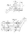
- FIG. 1 is a side view of a mowing machine, which mowing machine is provided with a pivotal arm 1, by means of which the mowing machine can be connected to a tractor or to a suchlike vehicle.
- the pivotal arm 1 Via hinge 2, the pivotal arm 1 is connected to the second frame 3 which is supported, capable of movement, by means of wheels 4 which by means of pivots 5 are pivotally connected to said second frame 3.
- the pivotal movement of each of the wheels 4 relative to the second frame 3 is effected by means of the hydraulic cylinder 6, whose length can be adjusted by means of the supply and discharge of a fluid through line 7.
- the hydraulic fluid is supplied from the vehicle drawing the machine via line 8, whereafter it passes through a flow divider 9 which provides each of the hydraulic cylinders 6 with equal quantities of fluid, so that the wheels 4 are pivoted to an equal extent relative to the second frame 3. This is in particular of importance when the vehicle drawing the mowing machine is not situated straight in front thereof, thus causing the weight distribution of the mowing machine over the two wheels 4 to be non-uniform.
- the embodiment shown in Figures 1, 2 and 3 is furthermore provided with a supporting beam 10 cum mower members 11.
- the mower members 11 are disc-shaped having at their outer periphery knives 12 and are capable of rotation about upwardly directed axes.
- the drive of the mower members 11 is located in the supporting beam 10.
- the two outermost mower members are provided with drum-shaped crop guides 13, which rotate along with the mower member.
- the supporting beam 10 is connected via arms 14 to the first frame 15.
- Said pivotal members 16, 17 are mounted pivotally on both the first frame 15 and the second frame 3.
- Said lower pivotal members 16 extend from the second frame 3 obliquely upwardly and forwardly to the first frame 15.
- the upper pivotal member 17 is adjustable in length and can be secured to the first frame 15 by means of a plurality of attaching points 18 located one above the other. By changing the length of the upper pivotal member 17 it is possible to change the position of the first frame 15 relative to the second frame 3, and by connecting the upper pivotal member 17 to a higher or lower attaching point 18 on the first frame 15 it is possible to change the relative movement of the two frames 3, 15 to some extent.
- the first frame 15 includes, located within the hollow pipe 19 (Figure 2), the main drive shaft 53 ( Figure 4) which is provided near its one end with the gear box 20 and near its other end with the gear box 21. Inside the gear box 20, the drive shaft 22 coming from the drawing vehicle is connected to the main drive shaft located in the hollow pipe 19. The drive will be described in further detail hereinafter with reference to Figure 4.
- the crop processing member 25 accommodated in the first frame 15 substantially consists of a horizontally extending tube 26, to which beater members 27 are fitted.
- Figure 3 shows only a few of said beater members 27.
- the tube 26 cum beater members 27 is capable of rotation about its longitudinal axis, i.e. in such a manner that the front side thereof moves upwardly.
- said beater members 27 which discharge the crop upwardly and rearwardly, whereby an advantageous processing of the crop is performed by the said beater members 27.
- two swath boards 28 are provided in the second frame 3.
- the swath boards 28 are mounted pivotally about vertical pins 29 ( Figure 2) in the second frame 3.
- the angle between the swath board 28 and the second frame 3 can be set by connecting the rod 30 in different places to the second frame 3.
- a plurality of apertures 31 have been provided for the purpose.
- the swath boards 28 are provided with a substantially vertical portion and an obliquely downwardly and forwardly curved portion, whereby the crop discharged to the rear by the crop processing member 25 can be guided in an optimum manner to the swath to be formed.
- a tilting element 35 is pivotal on both sides about a shaft 36 which extends substantially horizontally and in the direction of operative travel of the machine.
- a tensile spring 38 compensating for the force exercised by a tensile member 39 on said tilting element 35 is arranged between the tilting element 35 and a support 37 mounted on the second frame 3.
- Tensile member 39 which has one end attached to the tilting element 35, has its other end pivotally connected to the first frame 15.
- the positions where the tensile spring 38 and the tensile member 39 act on the tilting element 35 are such that, when the tensile spring 38 is extended, whereby the force exercised by said spring increases, the upward force exercised on the first frame 15 does not increase proportionally.
- This is the result of the use of tilting element 35, which converts the force exercised by the tensile spring 38 into a torque and thereafter converts said torque into a tensile force in tensile member 39. Since on rotation of the tilting element 35 both arms of said torques change, also the force changes so as to keep the torques equal.
- the tilting element 35 is of such a construction that on extension of the tensile spring 38, whereby the tensile force increases, either the associated arms of the torque exercised thereby on the tilting element 35 decreases, or the arm of the torque by means of which the tilting element 35 exercises a force on the first frame 15 increases.
- this is effected by the fact that the angle between the lines connecting the pivotal point 36 with the points of action of the tensile spring 38 and the tensile member 39, respectively, is less than 90° (indicated in Figure 3, right-hand side, by the letter A).
- Figures 2 and 3 show that the two wheels 4 are slightly out-of-straight relative to the direction of operative travel of the mowing machine. This misalignment of the wheels 4 results in the mowing machine driving straight on when the vehicle drawing the machine is not straight in front of but obliquely in front of the mowing machine, i.e. in the embodiment shown to the left in front of the mowing machine.
- the embodiment illustrated in Figures 1, 2 and 3 is furthermore provided with upwardly foldable screening hoods 40, 41 and 42.
- the screening hood 42 extends at the front side of the mowing machine, the screening hood 41 at the right-hand side and the screening hood 40 at the left-hand side of the mowing machine.
- the screening hoods are made of a metal frame covered with a plastic-coated cloth or any other type of flexible material, which material hangs loosely downwards all around.
- the screening hoods 40, 41 42 are foldable upwardly, i.e. about a substantially horizontal shaft located near the mowing machine.
- FIG. 3 This upwardly folding movement is shown in Figure 3 at the right-hand side by means of arrow 43, while in Figure 1 the folded-up position is indicated by means of broken lines.
- screening hood 42 at the front side of the implement is significantly less wide than the width of the mowing unit.
- a further screen is provided by the screening hoods 41 and 42 which, for that purpose, are extended inwardly at the front side.
- This extension denoted in Figure 2 by reference numeral 44, is moved downwardly when the laterally extending portions of the screening hoods 40 and 41 are folded upwardly. This is of particular importance since at the left-hand side of the mowing machine, the portion 44 of the screening hood 40 is located directly below the drive shaft 27, so that an upwardly folding movement is impossible.
- Figure 2 furthermore shows a hydraulic cylinder 45 which at its one end is pivotally connected to pivotal arm 1 and at its other end to the second frame 3.
- the pivotal angle of pivotal arm 1 relative to the mowing machine can be set.
- the cylinder 45 In the transport position, when the vehicle drawing the machine is approximately straight in front of the mowing machine, the cylinder 45 will be fully retracted, while the locking element 46, consisting of a spring-loaded, rotatable hook, falls into a recess 47 near the end of the piston rod of cylinder 45.
- the pivotal arm is blocked mechanically in the transport position. This blocking can be released by pulling the rope 48 from the vehicle drawing the machine, whereby the locking element 46 is removed from recess 47, whereafter by means of operating the hydraulic cylinder 45 the desired angular position of the pivotal arm can be adjusted.
- Figure 4 shows schematically an ingoing shaft 50 which is connected to the bevel gear wheel 51 in the gear box 20.
- the ingoing shaft 50 can be connected to the drive shaft 22 shown in the Figures 1 and 2.
- the bevel gear wheel 51 meshes with the bevel gear wheel 52, which is rigidly connected to the main drive shaft consisting of the sections 53 and 54.
- Section 53 of the main drive shaft 53, 54 reaches to into the gear box 21 and is therein rigidly connected to the bevel gear wheel 55, which meshes with the bevel gear wheel 56 connected to a drive shaft, the other end of which is connected to the outermost mower member 11 near one end of supporting beam 10.
- said outermost mower member 11 is driven via the main drive shaft 53, 54.
- the other outermost mower member 11 (near the other end of supporting beam 10) is driven via the bevel gear wheel 57, which is secured to the section 54 of the drive shaft 53, 54 and meshes with the bevel gear wheel 58 of a drive shaft connected to said other outermost mower member 11.
- the two gear boxes 20 and 21 are interconnected by the hollow pipe 19 wherein section 53 of the main drive shaft is accommodated, said hollow pipe 19 constituting part of the first frame 15. It will be obvious that by rotation of the ingoing shaft 50 the two outermost mower members 11 are driven.
- Section 54 of the main drive shaft 53, 54 extends sidewards to a further extent and at its end is provided with a rigidly connected flange 61, against which bears a flange 62 which is connected to a sleeve 63 provided coaxially about section 54 of the main drive shaft.
- the sleeve 63 is rotatable about section 54 of the main drive shaft, which rotation is blocked by a shear pin 64 which interconnects the two flanges 61, 62.
- the sleeve 63 is furthermore provided with a gear wheel 65, which meshes with a gear wheel 66 meshing in its turn with a gear wheel 67.
- the gear wheel 67 is connected to a shaft 68, on which a gear wheel 69 is mounted.
- the gear wheel 69 meshes with a gear wheel 70 mounted on a shaft 71.
- a gear wheel 72 is rigidly mounted on the shaft 71, which gear wheel 72 meshes with a gear wheel 73 which is rigidly mounted on a shaft 74 connected to the crop processing member 25, the tube 26 of which is shown in Figure 4.
- the shear pin 64 has for its object to provide protection against excessive forces on the drive, which forces can be produced both by blocking of ingoing shaft 50 or of the mowing unit on the one hand and by blocking of the crop processing member 25 on the other. Because of the relatively large mass inertia of both portions of the mowing machine, on blocking of either of said portions, the other portion will be disconnected therefrom by shearing of the shear pin. After shearing of the shear pin 64, it can be replaced by removing the cover 75 located at the side of the mowing machine and fitting a new shear pin.
- the mowing machine is furthermore provided with the removable cover 76, behind which the set of gear wheels 69, 70 is located.
- both gear wheels can be removed from their respective shafts 68, 71 and be replaced by gear wheels having a different transmission ratio or be interchanged, thus changing the transmission ratio.
- Figures 5, 6 and 7 illustrate an embodiment of a pivotal shaft, by means of which the mowing implement may be connected to a tractor or a suchlike vehicle.
- Figure 5 shows the position of the drawing vehicle 80 relative to the mowing machine during operation.
- the mowing machine is then located obliquely behind the drawing vehicle 80.
- the mowing machine includes the pivotal arm 1 which, as has been described already in the foregoing, can be fixed in the desired position relative to the mowing machine by means of the hydraulic cylinder 45.
- a cross-beam 81 is connected to the pivotal arm 1, which cross-beam 81, during operation, extends approximately perpendicularly to the direction of operative travel.
- a belt transmission 83 To the cross-beam 81 there is connected a belt transmission 83, the centre lines 84 and 85 of whose belt pulleys are indicated.
- the secondary belt pulley of the belt transmission 83 is connected via a universal joint 86 to the drive shaft 22, which via a universal joint 87 is connected to the ingoing shaft 50 of the drive of the mowing machine.
- the primary belt pulley of the belt transmission 83 is connected to the power take-off shaft of the drawing vehicle 80, which connection is not shown in further detail in the drawings.
- Figure 6 shows the mowing machine in the transport position, i.e. the vehicle 80 drawing the machine is approximately straight in front of the mowing machine.
- the hydraulic cylinder 85 is adjusted to its shortest position.
- Figure 6 furthermore shows that each of the oval mowing discs 11 can be rotated obliquely forwardly at an angle of 45° so as to achieve that the outermost mowing discs or the knives 12 connected thereto do not protrude outside the width of the mowing machine, so that the mowing machine width is limited to that legally permitted for transport by public road.
- the working width of the mowing machine can be significantly wider than this legally permitted transport width, which width is indicated in Figure 6 by the letter A.
- the permissible transport width can be approximately 3 meters ( Figure 6), while the working width of B ( Figure 5) of the same implement can be e.g. 3.16 metres.
- screening hoods, if any, extending over the mower members, at least to the extent in which they extend laterally, can be folded away.
- Figure 7 shows the belt transmission in further detail, the primary belt pulley 88 and the secondary belt pulley 89 having been indicated by broken lines. Additionally, there is shown that the lug 90 to be fitted to the drawing vehicle can be shifted relative to tube 91 and be locked therein in a plurality of positions by means of bolts 92. Furthermore, Figure 7 shows, in a plan view, a support 93 which can be positioned below the pivotal arm 1 of the mowing machine, when said mowing machine is disconnected from the drawing vehicle 80.
- Figures 8, 9 and 10 illustrate a second embodiment of the manner in which the mowing machine can be coupled to a vehicle drawing same.
- Figure 9 shows the manner in which the pivotal arm is connected to the mowing machine, the section 100 of the pivotal arm being connected pivotally about the shaft 101 to the second frame 3 of the mowing machine.
- Figure 9 shows the section 100 of the pivotal arm approximately in its operating position, said section 100 of the pivotal arm extending approximately parallel to the ingoing shaft 50 for driving the mowing machine.
- a cross-beam 102 ( Figure 8) having near each of its ends a pivotal connection 103 and 104, respectively, to the connecting beam 105 and connecting rod 106, respectively, which are both of approximately the same length.
- connecting beam 105 and the connecting rod 106 are connected pivotally to cross-beam 107, i.e. by means of pivotal connections 108 and 109 provided near the ends of the cross-beam 107, said cross-beam being rigidly connected by means of connecting elements 110 and 111 to the vehicle drawing the machine.
- Figure 10 is a side view of what is shown in Figure 8.
- the connection of the connecting beam 105 to each of the cross-beams 102, 107 is such that the connecting beam 105 can only pivot in one plane relative to each of the cross-beams 102, 107.
- the pivotal connections 104 and 109 of connecting rod 106 allow of a greater degree of freedom of movement, so that torques to be transferred via the pivotal arm are passed on via the connecting beam 105.
- the pivotal arm is also provided with drive shafts for driving the mowing machine from the drawing vehicle, for which purpose it is possible to connect the drive shaft 22 to the ingoing shaft 50 of the mowing machine via a universal joint (not shown), while the drive shaft 22 has its other end connected via a universal joint 113 to the drive shaft 114, which is connected to the outgoing shaft 116 of a gear box 117 via a universal joint 115.
- the gear box 117 includes the ingoing shaft 118 which via means (not shown) can be coupled to the power take-off shaft of the drawing vehicle.
- the length of the drive shaft 114 hardly need be adapted, in particular so when the centres of the universal joints 113, 115 are approximately located on the mean perpendiculars of the constant sides of the deformable quadrangle 103, 104, 108, 109, i.e. at some distance beyond said quadrangle.
- the drive also includes a gear box 117 having an ingoing shaft 118 and an outgoing shaft 116.
- Said gear box has a transmission ratio of approximately 1.36:1, so that, at a rate of 1,000 revs/min of the power take-off shaft, the rotational speed of the drive shafts 114 and 22 is approximately 735 revs/min.
- the gear box 117 is bolted to the connecting element 110 by means of bolts 119. When the mowing implement is drawn by a drawing vehicle, the speed of rotation of whose power take-off shaft is 540 revs/min, the gear box 117 can be inverted, i.e.
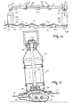
- FIGs 11, 12 and 13 show an embodiment of the mowing machine wherein the outermost mower members 121, 122 are driven. Said outermost mower members 121, 122 are mounted on a supporting beam 10, as are also the further mowing members 11.
- the supporting beam 10 is assembled from a plurality of adjacent sections 123, 124, each section 123 having gear wheels for driving the mower member 11 mounted thereon.
- the sections 123 are provided at the bottom side with a slide member 125 which is movable over the soil.
- the component sections 123, 124 of the supporting beam are held together by means of a tensile rod 127 ( Figure 12), which is provided with thread at both ends, so that by tightening nuts screwed thereon a compressive force is exerted on said sections 123, 124.
- a torsion shaft 128 ( Figure 12) of, in this embodiment, a square cross-section is provided in the supporting beam 10 parallel to the tensile rod 127. Inside each of the sections 123 of the supporting beam, said torsion shaft 128 extends through a gear wheel which is provided with a correspondingly square recess, so that on rotation of the torsion shaft via these gear wheels all the mower members are driven.
- the embodiment shown in Figures 11 and 12 comprises a frame 129 of which the hollow tube 19 forms part, a main drive shaft 53 being located within said hollow tube.
- Said main drive shaft 53 is fitted with a gear wheel 130 for the drive thereof.
- Said main drive shaft 53 is fitted near each of its ends with a bevel gear wheel 131, 132 via which the bevel gear wheels 133, 134 of the respective drive shafts 135 and 136 are driven.
- the drive shafts 135, 136 each have two universal joints 137, 138, 139, 140 and via said joints drive the two outermost mower members 121, 122.
- said two outermost mower members 121, 122, as are also all the other mower members 11, are drivably interconnected by means of a torsion shaft 128, all the mower members are driven on rotation of the main drive shaft 53.
- the drive from both sides of the interconnected series of mower members is enabled by the use of the torsion shaft 128, which accomplishes a flexible drive between each of the mower members. This accomplishes an optimum force distribution between the drives on both sides.
- FIG 12 shows in further detail the manner in which the drive shaft 136 is connected at one end to the mower member 122 and is provided at the other end with a bevel gear wheel 134 for its drive.
- the drive shaft 136 is assembled from three sections which are intercoupled by universal joints 139, 140, said joints being single joints in the embodiment shown.
- the section of the drive shaft 136 that is located between the universal joints is fitted with a drum-shaped member 141. Near its lower side, the drum-shaped member 141 is contiguous to an edge 142 attached to the mower member 122, while the drum-shaped member 141 is contiguous near its upper side to a section 143 which is rigidly connected to the frame 129.
- Figure 11 there is fitted to the frame 129 of the mowing unit a trestle 145, via which the mowing unit can be connected to a vehicle.
- a trestle 145 via which the mowing unit can be connected to a vehicle.
- the mowing unit shown can also be accommodated in the mowing machine, as is shown in the previous drawings.
- Figures 14 and 15 show a different embodiment, which differs from the one shown in Figures 11 and 12 in that the drive shafts 135, 136 are not provided with universal joints, while the frame 129 does not provide a connection between the supporting beam 10 and the superjacent frame.
- This connection is effected by the drive shafts 135, 136, one end of which is bearing-supported in the superjacent frame portion, which bearing is denoted in Figure 15 by reference numeral 146, and whose other end is rigidly connected to the outermost mower members 121, 122.
- An important advantage of such a construction is that the accumulation of crop against stationary frame portions is prevented.
- the embodiment shown in Figures 14 and 15 can also be connected, by means of a trestle 145, to a vehicle, or be accommodated in a mowing machine such as is described, for example, with reference to Figures 1, 2 and 3.
Landscapes
- Life Sciences & Earth Sciences (AREA)
- Environmental Sciences (AREA)
- Zoology (AREA)
- Engineering & Computer Science (AREA)
- Mechanical Engineering (AREA)
- Soil Sciences (AREA)
- Harvester Elements (AREA)
Applications Claiming Priority (2)
| Application Number | Priority Date | Filing Date | Title |
|---|---|---|---|
| NL8602866 | 1986-11-12 | ||
| NL8602866A NL8602866A (nl) | 1986-11-12 | 1986-11-12 | Maaimachine. |
Publications (3)
| Publication Number | Publication Date |
|---|---|
| EP0269166A2 true EP0269166A2 (de) | 1988-06-01 |
| EP0269166A3 EP0269166A3 (en) | 1989-08-30 |
| EP0269166B1 EP0269166B1 (de) | 1994-05-04 |
Family
ID=19848827
Family Applications (1)
| Application Number | Title | Priority Date | Filing Date |
|---|---|---|---|
| EP87202186A Expired - Lifetime EP0269166B1 (de) | 1986-11-12 | 1987-11-10 | Mähmaschine |
Country Status (5)
| Country | Link |
|---|---|
| US (1) | US4838013A (de) |
| EP (1) | EP0269166B1 (de) |
| AU (1) | AU595657B2 (de) |
| DE (1) | DE3789755T2 (de) |
| NL (1) | NL8602866A (de) |
Cited By (10)
| Publication number | Priority date | Publication date | Assignee | Title |
|---|---|---|---|---|
| EP0361573A1 (de) * | 1988-09-13 | 1990-04-04 | C. van der Lely N.V. | Mähmaschine |
| DE4019948A1 (de) * | 1989-06-29 | 1991-01-03 | Niemeyer Gmbh & Co Kg Soehne | Landwirtschaftliches anhaengegeraet |
| GB2243757A (en) * | 1990-05-08 | 1991-11-13 | Agri Patents Limited | Pasture topper |
| AT397596B (de) * | 1989-06-23 | 1994-05-25 | Poettinger Ohg Alois | Mähmaschine |
| EP0792574A1 (de) * | 1996-02-28 | 1997-09-03 | Deere & Company | Gezogenes Gerät |
| EP0795265A1 (de) * | 1996-03-06 | 1997-09-17 | Deere & Company | Anhängevorrichtung |
| EP0916249A1 (de) * | 1997-11-14 | 1999-05-19 | Kuhn S.A. | Mähmaschine |
| EP1110443A1 (de) * | 1999-12-24 | 2001-06-27 | Maasland N.V. | Mähaufbereiter |
| NL1037078C2 (nl) * | 2009-06-26 | 2010-12-28 | Lely Patent Nv | Landbouwmachine. |
| ITFO20130006A1 (it) * | 2013-10-22 | 2015-04-23 | Elvis Brighi | Attrezzo agricolo per la realizzazione di fasci confezionati di piante |
Families Citing this family (15)
| Publication number | Priority date | Publication date | Assignee | Title |
|---|---|---|---|---|
| NL8801039A (nl) * | 1988-04-21 | 1989-11-16 | Lely Nv C Van Der | Maaimachine. |
| DK26790A (da) * | 1990-02-01 | 1991-08-02 | Taarup As Maskinfab | Skaarlaegger |
| US5272859A (en) * | 1992-04-14 | 1993-12-28 | Hay & Forage Industries | Mechanical drive center pivot mower conditioner |
| US5463852A (en) | 1994-04-28 | 1995-11-07 | Hay & Forage Industries | Wide cut harvester having rotary cutter bed |
| US5433064A (en) | 1994-04-28 | 1995-07-18 | Hay & Forage Industries | Rotary cutter bed harvester with non-auger conveying means for outboard cutters |
| US6082085A (en) * | 1998-05-13 | 2000-07-04 | Agco Corporation | Foliage mowing implement having mechanical drive with main gearbox rotation |
| US6158201A (en) | 1998-09-15 | 2000-12-12 | Hay & Forage Industries | Rotary mower conditioner having improved cut crop flow |
| FR2786977B1 (fr) * | 1998-12-14 | 2001-02-16 | Kuhn Sa | Faucheuse comportant un dispositif centralise de reglage de la force d'allegement exercee sur le mecanisme de recolte |
| DE10121015A1 (de) * | 2001-04-28 | 2002-10-31 | Deere & Co | Antriebssystem |
| US7047714B1 (en) * | 2005-02-02 | 2006-05-23 | Deere & Company | Tongue swing cylinder arrangement for rotary side-pull mower-conditioner |
| US7669392B2 (en) | 2006-01-13 | 2010-03-02 | Cnh America Llc | Header height control system with flow divider capability |
| US7475530B2 (en) | 2007-03-02 | 2009-01-13 | Textron Inc. | Articulating swing-out arm |
| FR2930864B1 (fr) * | 2008-05-06 | 2012-11-09 | Kuhn Sa | Faucheuse avec un dispositif d'allegement perfectionne |
| US7726108B1 (en) | 2009-01-14 | 2010-06-01 | Agco Corporation | Wide cut rotary harvester having cut crop feeder mechanism |
| JP5753470B2 (ja) * | 2011-10-04 | 2015-07-22 | ヤンマー株式会社 | コンバイン |
Family Cites Families (26)
| Publication number | Priority date | Publication date | Assignee | Title |
|---|---|---|---|---|
| US1878346A (en) * | 1930-05-26 | 1932-09-20 | Oscar J Jauslin | Trailer cart |
| FR788790A (fr) * | 1934-07-19 | 1935-10-16 | Allied Machinery Company | Dispositif d'attelage pour remorque |
| US3088263A (en) * | 1961-04-06 | 1963-05-07 | Thompson Ralph | Crop processing machine |
| CH436820A (de) * | 1965-05-13 | 1967-05-31 | Bucher Guyer Ag Masch | Mähwerk |
| US3672132A (en) * | 1970-02-05 | 1972-06-27 | Int Harvester Co | Push over bar |
| ES399815A1 (es) * | 1972-02-15 | 1974-12-01 | Zazurca Larroya | Perfeccionamientos en maquinas segadoras, acondicionadoras,secadoras e hileradoras agricolas. |
| DE2349176B2 (de) * | 1973-09-29 | 1980-01-10 | Hesston Corp., Hesston, Kan. (V.St.A.) | Mähschwader |
| US3958399A (en) * | 1975-02-18 | 1976-05-25 | Sperry Rand Corporation | Header attachment structure |
| NL158056B (nl) * | 1975-02-28 | 1978-10-16 | Multinorm Bv | Inrichting voor het maaien van gewas en het vervolgens kneuzen daarvan. |
| US4081946A (en) * | 1976-12-01 | 1978-04-04 | Sperry Rand Corporation | Header suspension and lift means |
| GB1583983A (en) * | 1977-04-05 | 1981-02-04 | Sperry Ltd | Harvesting machines |
| US4182099A (en) * | 1977-11-21 | 1980-01-08 | Deere & Company | Impeller mower-conditioner rotor |
| NL171955C (nl) * | 1978-05-26 | 1983-06-16 | Zweegers P | Maaimachine. |
| DE2839841C2 (de) * | 1978-09-13 | 1987-03-05 | Klöckner-Humboldt-Deutz AG Zweigniederlassung Fahr, 7702 Gottmadingen | Mähwerk |
| US4206582A (en) * | 1979-02-12 | 1980-06-10 | International Harvester Company | Header lift arrangement for windrowers |
| NL193337C (nl) * | 1981-05-27 | 1999-07-02 | Lely Nv C Van Der | Maaimachine. |
| DE8125294U1 (de) * | 1981-08-29 | 1987-02-12 | MAN Technologie GmbH, 8000 München | Kupplungseinrichtung zwischen Lastkraftwagen und Anhänger |
| DE3246572C2 (de) * | 1982-12-16 | 1986-01-02 | Dieter 4422 Ahaus Orthaus | Lastzug mit Zwangslenkung |
| NL8300800A (nl) * | 1983-03-04 | 1984-10-01 | Multinorm Bv | Maaiinrichting met verbeterde aandrijving en/of gewasscheidingstrommel. |
| FR2560484B1 (fr) * | 1984-03-02 | 1991-05-31 | Sperry Corp | Mecanisme de flottement du collecteur d'une faucheuse-conditionneuse |
| FR2562758B1 (fr) * | 1984-04-12 | 1988-05-20 | Kuhn Sa | Faucheuse |
| US4573309A (en) * | 1984-06-13 | 1986-03-04 | Macdon Industries Ltd. | Pull-type windrower |
| GB2171884A (en) * | 1985-03-05 | 1986-09-10 | Deere & Co | Hitching arrangement for an implement pulled by a tractor |
| US4676053A (en) * | 1985-07-05 | 1987-06-30 | Hesston Corporation | Quick adjust flotation apparatus for a crop harvester |
| US4724661A (en) * | 1986-09-04 | 1988-02-16 | New Holland Inc. | Two piece crop harvesting header and flotation mechanism therefor |
| US4723401A (en) * | 1986-09-24 | 1988-02-09 | New Holland Inc. | Steerable wheel assembly for unitized rakes |
-
1986
- 1986-11-12 NL NL8602866A patent/NL8602866A/nl not_active Application Discontinuation
-
1987
- 1987-11-10 EP EP87202186A patent/EP0269166B1/de not_active Expired - Lifetime
- 1987-11-10 DE DE3789755T patent/DE3789755T2/de not_active Expired - Fee Related
- 1987-11-10 US US07/119,384 patent/US4838013A/en not_active Expired - Lifetime
- 1987-11-10 AU AU80969/87A patent/AU595657B2/en not_active Ceased
Cited By (15)
| Publication number | Priority date | Publication date | Assignee | Title |
|---|---|---|---|---|
| EP0361573A1 (de) * | 1988-09-13 | 1990-04-04 | C. van der Lely N.V. | Mähmaschine |
| AT397596B (de) * | 1989-06-23 | 1994-05-25 | Poettinger Ohg Alois | Mähmaschine |
| DE4019948A1 (de) * | 1989-06-29 | 1991-01-03 | Niemeyer Gmbh & Co Kg Soehne | Landwirtschaftliches anhaengegeraet |
| GB2243757A (en) * | 1990-05-08 | 1991-11-13 | Agri Patents Limited | Pasture topper |
| EP0792574A1 (de) * | 1996-02-28 | 1997-09-03 | Deere & Company | Gezogenes Gerät |
| EP0795265A1 (de) * | 1996-03-06 | 1997-09-17 | Deere & Company | Anhängevorrichtung |
| EP0916249A1 (de) * | 1997-11-14 | 1999-05-19 | Kuhn S.A. | Mähmaschine |
| FR2770965A1 (fr) * | 1997-11-14 | 1999-05-21 | Kuhn Sa | Machine de coupe comportant un dispostif d'entrainement perfectionne |
| EP1110443A1 (de) * | 1999-12-24 | 2001-06-27 | Maasland N.V. | Mähaufbereiter |
| WO2001047343A1 (de) * | 1999-12-24 | 2001-07-05 | Maasland N.V. | Mähaufbereiter |
| NL1037078C2 (nl) * | 2009-06-26 | 2010-12-28 | Lely Patent Nv | Landbouwmachine. |
| WO2010151111A1 (en) * | 2009-06-26 | 2010-12-29 | Lely Patent N.V. | Agricultural machine |
| US8555606B2 (en) | 2009-06-26 | 2013-10-15 | Lely Patent N.V. | Agricultural machine movable between a lateral transport position and an operative position |
| US9125337B2 (en) | 2009-06-26 | 2015-09-08 | Lely Patent N.V. | Agricultural machine movable between a lateral transport position and an operative position |
| ITFO20130006A1 (it) * | 2013-10-22 | 2015-04-23 | Elvis Brighi | Attrezzo agricolo per la realizzazione di fasci confezionati di piante |
Also Published As
| Publication number | Publication date |
|---|---|
| NL8602866A (nl) | 1988-06-01 |
| EP0269166A3 (en) | 1989-08-30 |
| AU8096987A (en) | 1988-05-19 |
| DE3789755D1 (de) | 1994-06-09 |
| US4838013A (en) | 1989-06-13 |
| AU595657B2 (en) | 1990-04-05 |
| EP0269166B1 (de) | 1994-05-04 |
| DE3789755T2 (de) | 1994-12-08 |
Similar Documents
| Publication | Publication Date | Title |
|---|---|---|
| EP0269166A2 (de) | Mähmaschine | |
| US4719742A (en) | Mowing machine | |
| RU2050101C1 (ru) | Косилка | |
| SU1019987A3 (ru) | Сельскохоз йственное орудие | |
| US4858418A (en) | Mowing machine | |
| US6109012A (en) | Hay-making machine | |
| AU632829B2 (en) | A mowing machine | |
| NZ195177A (en) | Power transmitting and coupling device for connecting tractor to implement | |
| EP0068560B1 (de) | Mähmaschine | |
| EP0155063B1 (de) | Mähmaschine | |
| US3543490A (en) | Flexible rotary mower | |
| GB2023393A (en) | Mowing device | |
| US5109655A (en) | Articulating rotary mower | |
| US4951450A (en) | Mowing machine | |
| IE46403B1 (en) | Improvements in or relating to mowing machines | |
| GB2149635A (en) | A machine, such as a hedge cutter, for performing operations on vegetation | |
| NL9301441A (nl) | Maaimachine. | |
| DK9500313U4 (da) | Liftophængt slåmaskine | |
| GB2118813A (en) | Mower cutter unit | |
| WO1992009190A1 (en) | Mower conditioner | |
| EP0672336B1 (de) | Mäher | |
| WO1995001715A1 (en) | A mower | |
| CN114982464B (zh) | 一种带全向可调式割晒台的割晒机 | |
| PL246945B1 (pl) | Kosiarka rotacyjna górnonapędowa z segmentową ramą główną | |
| EP0251409B1 (de) | Mähmaschine |
Legal Events
| Date | Code | Title | Description |
|---|---|---|---|
| PUAI | Public reference made under article 153(3) epc to a published international application that has entered the european phase |
Free format text: ORIGINAL CODE: 0009012 |
|
| AK | Designated contracting states |
Kind code of ref document: A2 Designated state(s): DE FR GB NL |
|
| PUAL | Search report despatched |
Free format text: ORIGINAL CODE: 0009013 |
|
| AK | Designated contracting states |
Kind code of ref document: A3 Designated state(s): DE FR GB NL |
|
| 17P | Request for examination filed |
Effective date: 19900111 |
|
| 17Q | First examination report despatched |
Effective date: 19911104 |
|
| GRAA | (expected) grant |
Free format text: ORIGINAL CODE: 0009210 |
|
| AK | Designated contracting states |
Kind code of ref document: B1 Designated state(s): DE FR GB NL |
|
| PG25 | Lapsed in a contracting state [announced via postgrant information from national office to epo] |
Ref country code: NL Effective date: 19940504 Ref country code: FR Effective date: 19940504 |
|
| REF | Corresponds to: |
Ref document number: 3789755 Country of ref document: DE Date of ref document: 19940609 |
|
| EN | Fr: translation not filed | ||
| NLV1 | Nl: lapsed or annulled due to failure to fulfill the requirements of art. 29p and 29m of the patents act | ||
| PG25 | Lapsed in a contracting state [announced via postgrant information from national office to epo] |
Ref country code: GB Effective date: 19941110 |
|
| PLBE | No opposition filed within time limit |
Free format text: ORIGINAL CODE: 0009261 |
|
| STAA | Information on the status of an ep patent application or granted ep patent |
Free format text: STATUS: NO OPPOSITION FILED WITHIN TIME LIMIT |
|
| 26N | No opposition filed | ||
| GBPC | Gb: european patent ceased through non-payment of renewal fee |
Effective date: 19941110 |
|
| PGFP | Annual fee paid to national office [announced via postgrant information from national office to epo] |
Ref country code: DE Payment date: 20021202 Year of fee payment: 16 |
|
| PG25 | Lapsed in a contracting state [announced via postgrant information from national office to epo] |
Ref country code: DE Free format text: LAPSE BECAUSE OF NON-PAYMENT OF DUE FEES Effective date: 20040602 |