EP0269365A2 - Optischer Wellenleiter - Google Patents
Optischer Wellenleiter Download PDFInfo
- Publication number
- EP0269365A2 EP0269365A2 EP87310207A EP87310207A EP0269365A2 EP 0269365 A2 EP0269365 A2 EP 0269365A2 EP 87310207 A EP87310207 A EP 87310207A EP 87310207 A EP87310207 A EP 87310207A EP 0269365 A2 EP0269365 A2 EP 0269365A2
- Authority
- EP
- European Patent Office
- Prior art keywords
- wave guide
- optical
- wavelength
- refractive index
- optical wave
- Prior art date
- Legal status (The legal status is an assumption and is not a legal conclusion. Google has not performed a legal analysis and makes no representation as to the accuracy of the status listed.)
- Withdrawn
Links
Images


Classifications
-
- G—PHYSICS
- G02—OPTICS
- G02B—OPTICAL ELEMENTS, SYSTEMS OR APPARATUS
- G02B6/00—Light guides; Structural details of arrangements comprising light guides and other optical elements, e.g. couplings
- G02B6/24—Coupling light guides
- G02B6/26—Optical coupling means
-
- G—PHYSICS
- G02—OPTICS
- G02B—OPTICAL ELEMENTS, SYSTEMS OR APPARATUS
- G02B6/00—Light guides; Structural details of arrangements comprising light guides and other optical elements, e.g. couplings
- G02B6/24—Coupling light guides
- G02B6/26—Optical coupling means
- G02B6/28—Optical coupling means having data bus means, i.e. plural waveguides interconnected and providing an inherently bidirectional system by mixing and splitting signals
- G02B6/2804—Optical coupling means having data bus means, i.e. plural waveguides interconnected and providing an inherently bidirectional system by mixing and splitting signals forming multipart couplers without wavelength selective elements, e.g. "T" couplers, star couplers
- G02B6/2821—Optical coupling means having data bus means, i.e. plural waveguides interconnected and providing an inherently bidirectional system by mixing and splitting signals forming multipart couplers without wavelength selective elements, e.g. "T" couplers, star couplers using lateral coupling between contiguous fibres to split or combine optical signals
-
- G—PHYSICS
- G02—OPTICS
- G02B—OPTICAL ELEMENTS, SYSTEMS OR APPARATUS
- G02B6/00—Light guides; Structural details of arrangements comprising light guides and other optical elements, e.g. couplings
- G02B6/10—Light guides; Structural details of arrangements comprising light guides and other optical elements, e.g. couplings of the optical waveguide type
Definitions
- the present invention relates to an optical wave guide and, although the invention is not so restricted, it relates more particularly to an optical wave guide coupler (hereinafter referred to as an optical coupler) having a plurality of wave guide portions each of which is clad by a cladding portion.
- Such wave guide portions may, for example, be constituted by planar optical wave guides or by optical fibres.
- Such an optical wave guide may be used in optical communication networks or for optical measurements.
- the difference in the refractive index between a light guiding member and a cladding member in a known optical coupler is almost constant over the range of wavelengths between visible rays and near-infrared rays. Consequently, in a known optical coupler, the spot size of the propagation mode (the width of the expansion of the electromagnetic field) increases in proportion to the increase of the wavelength. Moreover, the coupling coefficient of the known optical coupler varies in simple linearity in response to the change of the wavelength, and therefore a desired coupling coefficient and splitting or divergence ratio can be obtained only over a very narrow wavelength range.
- a low wavelength dependent 3 dB coupler using a complex structure has been described in AIAN, J.: "A new idea for wavelenth-insensitive fibre couplers", IEE Electronics Division Colloquium on Advance Fibre Waveguide Devices, May 1986.
- this has a relatively large excess loss.
- the coupling coefficient and splitting ratio which it is desired to obtain are limited to a very narrow wavelength range and consequently such a coupler is not suitable for spectrum measurement or propagation of multiple wavelengths. Even when a coupler is made less wavelength dependent by providing it with a complex structure, the excess loss is large.
- an optical wave guide having at least one wave guide portion which is clad by a cladding portion between whose refractive index and that of the wave guide portion there is a refractive index difference characterised in that the refractive index difference increases as the wavelength of the light propagated through the wave guide increases.
- the wave guide is an optical coupler having a plurality of parallel wave guide portions each of which is clad by a cladding portion.
- the or each wave guide portion clad by a cladding portion is constituted by optical fibre material.
- the or each wave guide portion comprises a planar optical guide.
- the optical wave guide may be an optical coupler whose coupling coefficient remains substantially constant over a wavelength range of at least 0.2 ⁇ m.
- the optical wave guide may also be an optical coupler having a splitting ratio of substantially ⁇ 1 over a wavelength range of at least 0.2 ⁇ m.
- the electromagnetic field of the fundamental mode extends between the propagation guides, and the luminous energy couples with an extremely low excess loss. If it is desired that the optical coupling occurs to a constant extent, the spot size of the mode has to be kept constant. If the difference in refractive index between the light guiding member and the cladding member is almost constant with respect to the change of the wavelength, the spot size enlarges as the wavelength increases and thus the coupling coefficient changes.
- an optical coupler of this type can obtain an almost constant coupling coefficient and an almost constant splitting ratio over the abovementioned wide wavelength range.
- Figure 1 shows the variation with wavelength of the refractive indices of the guide (core) and cladding portions of an optical fibre coupler which is shown in Figure 2 and which is to be used for calculating the propagation modes of an optical fibre coupler.
- the refractive index of each of two light guide members or optical fibre cores 1 are larger than that of its cladding member 2.
- the diameter of each light guide member 1 is 2 a , and the light guide members 1 are placed at a distance 2 d apart from each other.
- SSKI of Schott Co. and TiF6 of Schott Co. are chosen as the materials for the two optical fibre cores 1 and for the cladding members 2 respectively.
- the refractive index difference between the refractive index of each light guide member 1 and that of its respective cladding member 2 increases as the wavelength of the light propagated through the optical coupler increases.
- the refractive index difference between the two members as defined as (n co ⁇ n cl )/n co .
- the refractive index difference between the two materials increases from 0.16% at the wavelength 0.644 ⁇ m to 0.47% at the wavelength 1.014 ⁇ m.
- the coupling coefficient of this structure is shown as a solid line in Figure 3.
- the refractive index and the coupling coefficient have the following relationship:- where d is the distance between the centres of the two cores 1; k is the propagation coefficient in the formulae referred to below; Ko is a modified Bessel function of a first kind; K1 is a modified Bessel function of a second kind; and U,V and W are well known fibre parameters which are defined as follows: where a is the core radius, and ⁇ is the propagation coefficient of the fundamental mode in the direction of the axis of the optical fibre.
- the coupling coefficient C becomes a constant regardless of the wavelength of the incident light ⁇ .
- the broken line in Figure 3 shows the coupling coefficient of known materials whose refractive indices are almost the same as those of the above-mentioned materials at a wavelength of 0.8 ⁇ m and whose refractive index difference is almost non-wavelength dependent.
- the coupling coefficient change of the embodiment of the invention, as shown by the solid line is remarkably small at a wavelength of about between 0.64 ⁇ m and 0.85 ⁇ m.
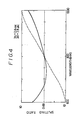
- the solid line in Figure 4 shows calculated values of the splitting ratio at the two output terminals of a 3dB optical coupler (splitting ratio of 1:1) which may be formed by a construction according to the present invention.
- the splitting ratio R is given as follows: where ⁇ is a value equivalent to a half of the difference of propagation coefficients between the two optical fibres in the fundamental mode, C is the above-mentioned coupling coefficient, Z is the effective coupling length, and ⁇ C is given by
- the splitting ratio R becomes less wavelength-dependent.
- the splitting ratio obtained in this embodiment is around ⁇ 1 dB over the wavelength between 0.65 ⁇ m and 0.85 ⁇ m.
- a construction using known materials has the characteristic shown by the broken line in Figure 3, where the wavelength range covering the splitting ratio ⁇ 1 dB is very narrow.
- the present invention provides an optical coupler which has little dependence on wavelength and, with a low excess loss, is suitable for spectral measurement and multiple wavelength transmission.
Landscapes
- Physics & Mathematics (AREA)
- General Physics & Mathematics (AREA)
- Optics & Photonics (AREA)
- Optical Integrated Circuits (AREA)
Applications Claiming Priority (2)
| Application Number | Priority Date | Filing Date | Title |
|---|---|---|---|
| JP61278210A JPS63131105A (ja) | 1986-11-21 | 1986-11-21 | 光結合器 |
| JP278210/86 | 1986-11-21 |
Publications (2)
| Publication Number | Publication Date |
|---|---|
| EP0269365A2 true EP0269365A2 (de) | 1988-06-01 |
| EP0269365A3 EP0269365A3 (de) | 1988-10-26 |
Family
ID=17594130
Family Applications (1)
| Application Number | Title | Priority Date | Filing Date |
|---|---|---|---|
| EP87310207A Withdrawn EP0269365A3 (de) | 1986-11-21 | 1987-11-19 | Optischer Wellenleiter |
Country Status (3)
| Country | Link |
|---|---|
| EP (1) | EP0269365A3 (de) |
| JP (1) | JPS63131105A (de) |
| KR (1) | KR880006558A (de) |
Cited By (1)
| Publication number | Priority date | Publication date | Assignee | Title |
|---|---|---|---|---|
| EP0660550A1 (de) * | 1993-12-20 | 1995-06-28 | AT&T Corp. | Sohton-Übertragungssystemzwischenverstärker mit Gleitfrequenzleitfiltern |
Family Cites Families (1)
| Publication number | Priority date | Publication date | Assignee | Title |
|---|---|---|---|---|
| US3244075A (en) * | 1961-02-09 | 1966-04-05 | American Optical Corp | Dispersive type optical filter utilizing light-transmitting fiber elements |
-
1986
- 1986-11-21 JP JP61278210A patent/JPS63131105A/ja active Pending
-
1987
- 1987-11-19 EP EP87310207A patent/EP0269365A3/de not_active Withdrawn
- 1987-11-21 KR KR870013128A patent/KR880006558A/ko not_active Withdrawn
Cited By (1)
| Publication number | Priority date | Publication date | Assignee | Title |
|---|---|---|---|---|
| EP0660550A1 (de) * | 1993-12-20 | 1995-06-28 | AT&T Corp. | Sohton-Übertragungssystemzwischenverstärker mit Gleitfrequenzleitfiltern |
Also Published As
| Publication number | Publication date |
|---|---|
| KR880006558A (ko) | 1988-07-23 |
| JPS63131105A (ja) | 1988-06-03 |
| EP0269365A3 (de) | 1988-10-26 |
Similar Documents
| Publication | Publication Date | Title |
|---|---|---|
| US6005999A (en) | Waveguide narrowband rejection filter | |
| US6876791B2 (en) | Diffraction grating device | |
| Wagatsuma et al. | Mode conversion and optical filtering of obliquely incident waves in corrugated waveguide filters | |
| EP2264494A2 (de) | Glasfaserfilter zur Unterdrückung von verstärkter spontaner Emission | |
| US5883990A (en) | Low transmission loss optical fiber having a grating | |
| JPH07109447B2 (ja) | 光デバイスおよび光フィルター | |
| US6430341B1 (en) | Waveguide coupler | |
| Mizrahi et al. | Four channel fibre grating demultiplexer | |
| US20090041415A1 (en) | Double-core optical fiber | |
| US7215854B2 (en) | Low-loss optical waveguide crossovers using an out-of-plane waveguide | |
| EP0027223B1 (de) | Optische Einmodenfasern | |
| Mao et al. | An ARROW optical wavelength filter: design and analysis | |
| EP1430342B1 (de) | Entzerrung des durchlassbandes in einem wellenleitergitter | |
| EP0667542A1 (de) | Breitbandiger integriert-optischer Richtkoppler | |
| EP1436657B1 (de) | Optischer filter | |
| EP0295039A2 (de) | Optischer Wellenleiterkoppler | |
| US5031989A (en) | Optical filter coupler | |
| US7224868B2 (en) | Radiation-free optical cavity | |
| Morishita et al. | In-line optical fibre filters using dispersive materials | |
| KR100405968B1 (ko) | 모드 변환을 이용한 광결합 시스템 | |
| KR20000040493A (ko) | 파장분할다중 광통신 시스템에서의 커플러형 추가/추출 필터 | |
| EP0274218A1 (de) | Wellenlängenfilter | |
| Denturck et al. | Design of an integrated optic grating demultiplexer | |
| Kobayashi et al. | A New Design of Wavelength Division Multiplexing Filter | |
| JPH1164670A (ja) | グレーティング内蔵形光カップラ |
Legal Events
| Date | Code | Title | Description |
|---|---|---|---|
| PUAI | Public reference made under article 153(3) epc to a published international application that has entered the european phase |
Free format text: ORIGINAL CODE: 0009012 |
|
| AK | Designated contracting states |
Kind code of ref document: A2 Designated state(s): CH DE FR GB LI |
|
| PUAL | Search report despatched |
Free format text: ORIGINAL CODE: 0009013 |
|
| AK | Designated contracting states |
Kind code of ref document: A3 Designated state(s): CH DE FR GB LI |
|
| 17P | Request for examination filed |
Effective date: 19890404 |
|
| 17Q | First examination report despatched |
Effective date: 19911223 |
|
| STAA | Information on the status of an ep patent application or granted ep patent |
Free format text: STATUS: THE APPLICATION IS DEEMED TO BE WITHDRAWN |
|
| 18D | Application deemed to be withdrawn |
Effective date: 19920505 |
|
| RIN1 | Information on inventor provided before grant (corrected) |
Inventor name: TAKEMURA, YASUHIRO Inventor name: TAKESUE, TOSHIHARU |