EP0269464B1 - Alimentation d'un mélange solide-liquide - Google Patents
Alimentation d'un mélange solide-liquide Download PDFInfo
- Publication number
- EP0269464B1 EP0269464B1 EP87310549A EP87310549A EP0269464B1 EP 0269464 B1 EP0269464 B1 EP 0269464B1 EP 87310549 A EP87310549 A EP 87310549A EP 87310549 A EP87310549 A EP 87310549A EP 0269464 B1 EP0269464 B1 EP 0269464B1
- Authority
- EP
- European Patent Office
- Prior art keywords
- solid
- feeding
- liquid mixture
- mixture
- feed
- Prior art date
- Legal status (The legal status is an assumption and is not a legal conclusion. Google has not performed a legal analysis and makes no representation as to the accuracy of the status listed.)
- Expired - Lifetime
Links
- 239000000203 mixture Substances 0.000 title claims description 68
- 239000007788 liquid Substances 0.000 title claims description 62
- 239000007787 solid Substances 0.000 claims description 31
- 238000000034 method Methods 0.000 claims description 10
- 238000000151 deposition Methods 0.000 claims description 5
- 230000005484 gravity Effects 0.000 claims description 5
- 238000012856 packing Methods 0.000 description 10
- 238000010276 construction Methods 0.000 description 5
- 239000002245 particle Substances 0.000 description 5
- 238000012360 testing method Methods 0.000 description 5
- 239000011343 solid material Substances 0.000 description 4
- 238000012546 transfer Methods 0.000 description 4
- 235000010469 Glycine max Nutrition 0.000 description 2
- 244000068988 Glycine max Species 0.000 description 2
- 238000013019 agitation Methods 0.000 description 2
- 230000006378 damage Effects 0.000 description 2
- XLYOFNOQVPJJNP-UHFFFAOYSA-N water Substances O XLYOFNOQVPJJNP-UHFFFAOYSA-N 0.000 description 2
- 230000009471 action Effects 0.000 description 1
- 230000015572 biosynthetic process Effects 0.000 description 1
- 238000007664 blowing Methods 0.000 description 1
- 230000008859 change Effects 0.000 description 1
- 235000021438 curry Nutrition 0.000 description 1
- 238000010586 diagram Methods 0.000 description 1
- 238000007667 floating Methods 0.000 description 1
- 238000003780 insertion Methods 0.000 description 1
- 230000037431 insertion Effects 0.000 description 1
- 238000004519 manufacturing process Methods 0.000 description 1
- 239000000463 material Substances 0.000 description 1
- 230000009467 reduction Effects 0.000 description 1
- 239000011369 resultant mixture Substances 0.000 description 1
- 235000015067 sauces Nutrition 0.000 description 1
- 235000014347 soups Nutrition 0.000 description 1
- 235000013547 stew Nutrition 0.000 description 1
Images






Classifications
-
- B—PERFORMING OPERATIONS; TRANSPORTING
- B01—PHYSICAL OR CHEMICAL PROCESSES OR APPARATUS IN GENERAL
- B01F—MIXING, e.g. DISSOLVING, EMULSIFYING OR DISPERSING
- B01F27/00—Mixers with rotary stirring devices in fixed receptacles; Kneaders
- B01F27/60—Mixers with rotary stirring devices in fixed receptacles; Kneaders with stirrers rotating about a horizontal or inclined axis
- B01F27/70—Mixers with rotary stirring devices in fixed receptacles; Kneaders with stirrers rotating about a horizontal or inclined axis with paddles, blades or arms
-
- B—PERFORMING OPERATIONS; TRANSPORTING
- B65—CONVEYING; PACKING; STORING; HANDLING THIN OR FILAMENTARY MATERIAL
- B65B—MACHINES, APPARATUS OR DEVICES FOR, OR METHODS OF, PACKAGING ARTICLES OR MATERIALS; UNPACKING
- B65B37/00—Supplying or feeding fluent-solid, plastic, or liquid material, or loose masses of small articles, to be packaged
- B65B37/08—Supplying or feeding fluent-solid, plastic, or liquid material, or loose masses of small articles, to be packaged by rotary feeders
Definitions
- the present invention relates to a method of feeding a solid-liquid mixture and an apparatus therefor, for example a method of feeding or dispensing a solid-liquid mixture such as stew, soup, curry and sauce into a container such as packing bags as well as an apparatus therefor.
- GB-A-2 146 617 discloses an apparatus in accordance with the preamble of claim 4 in which a solid-liquid mixture is fed to a container while agitating the mixture with paddle blades.
- particles of the solid component present in the mixture collide with each other due to the agitation as well as the blades collide with the solid particles.
- the solid particles are damaged and are destroyed.
- bubbles are formed in the solid-liquid mixture depending on the rotational speed of the blades, which leads to a lowering of the commercial value of the resultant goods and the reduction of the precision in the metering of the mixture during filling.
- the present invention provides a method of feeding a mixture composed of at least one liquid component and at least one solid component having a specific gravity greater than that of the liquid component into a container, the method comprising depositing the solid component in the vicinity of a feed opening disposed at the bottom of a mixing container and feeding the solid-liquid mixture through the feed opening to a container, such as a packing bag.
- the present invention provides an apparatus for feeding a solid-liquid mixture comprised of at least one liquid component and at least one solid component having a specific gravity greater than that of the liquid in a desired mixing ratio which comprises a mixing container, a feed opening disposed at the bottom of the mixing container, and a feed controlling device disposed below or within the feed opening, characterised in that it further comprises a collecting device disposed in the mixing container for depositing the solid component of the mixture around the feed opening.
- the area of the feed opening may be adjustable .
- Figure 1 shows apparatus which comprises a bowl shaped container 1 for mixing a solid-liquid mixture M, a feed and shut-off device 2 for feeding and shutting off the mixture contained in the container 1, which is disposed at the bottom of the container 1 and a feed controlling device 4 for adjusting the minimal sectional area of the path for feeding the mixture M therethrough and disposed below the feed and shut-off device 2, the feed controlling device 4 being connected to a known filling device 6.
- the internal surface of the mixing container 1 is constituted by a part of a spherical surface. However, it is also possible to constitute the surface thereof by a member in the form of an inverted truncated cone provided with a feed and shut-off device 2 at its lower narrower end.
- the feed and shut-off device 2 comprises a shut-off plate 10 which is inserted in and withdrawn from a feed path 12.
- the feed controlling device 4 is constructed so that a plurality of plates 16 each having a through hole 14 of a different size, which are previously prepared, can be selectively inserted into the feed path 12 from one side of the feed path.
- a liquid component 20 is mixed with a solid component 22 of a specific gravity greater than that of the liquid in the mixing container and the solid component 22 is deposited on the bottom of the mixing container.
- the shut-off plate 10 is withdrawn from the feed path 12 while inserting a selected plate 16 having an opening 14 of a desired size into the feed path 12.
- the liquid component 20 and the solid component 22 deposited on the bottom of the container 1 are transferred to a filling or dispensing device 6 through the feed path 12 while maintaining a desired mixing ratio of the mixture.
- a feed controlling device 30 is constructed so that the feed amount and the mixing ratio of the mixture M can be controlled by adjusting the position of the feed controlling plate 32 to be inserted into the feed path 12.
- the insertion of the feed controlling plate 32 into the path is achieved by the reciprocating motion or the rotational motion of the feed controlling plate 32 within a plane perpendicular to the feed path 12.
- a feed controlling device 40 comprises a rotatable plate 44 having a plurality of through holes 42 of different diameters, formed on the same pitch circle and provided with a handle 46.
- any one of the circular holes 42 may selectively be located within the feed path 12 by rotating the handle 46.
- a feed controlling device 51 is constructed so that a plurality of plates 52 previously prepared, each having a through hole 50 of a different area, may selectively be inserted into the feed path 12 from inside the mixing container 1. In this apparatus, it is desirable that the feed and shut-off device be placed below the feed controlling device 51.
- a feed controlling device 61 is provided with a plurality of plates 62 each having a through hole 60 of a different area, as in the apparatus shown in Figure 5.
- the plates having through holes are arranged at the side of the feed path 12 while they are superposed on one another and are constructed so that any one of them can be selectively inserted into the feed path 12.
- a feed controlling device 71 comprises a cylindrical member 70 having a plurality of circular through holes 72, each being perpendicular to the axial line 73 of the cylindrical member and which are formed within the same cross-section thereof.
- the cylindrical member is engaged with the feed path 12 so as to be able to freely rotate around the axial line 73.
- the minimal cross section of the feed path 12 is determined by selecting any particular through hole 72 and arranging it so as to be parallel to the feed path 12.
- a feed controlling device comprises a flexible tube constituting a part of the feed path and a adjustable clamping device disposed outside the flexible tube.
- the mixing ratio of the mixture is controlled and/or adjusted by changing the size of the minimal cross section of the flexible tube for feeding the mixture therethrough, which is effected by operating the clamping device.
- a feed controlling device comprises a variable throttling device like an iris located within the feed path. If the variable throttling device is one capable of complete shut-off of the feed path, the use of the feed and shut-off device may be omitted.
- the mixing ratio may be controlled by adjusting the degree of throttling of the variable throttling device.
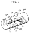
- a cylindrical container 100 is installed horizontally.
- a solid-liquid inlet opening 102 for introducing a solid-liquid mixture into the cylindrical container 100
- a sight through window 104 for observing the interior of the container 100.
- a solid-liquid outlet opening 106 for transferring the mixture, the outlet opening communicating with the feed controlling device (not shown).
- a rotary shaft 108 having an axis coincident with the axial line of the mixing container is placed and two groups of collecting blades 110 and 112, each comprising two blades, are disposed around the shaft symmetrically with respect to the center of the solid-liquid outlet opening 106.
- a collecting device 114 comprised of the rotary shaft 108 and the collecting blades 110 and 112 fixed around the shaft, is rotated at a relatively low speed by the action of a driving device (not shown) and thus the solid component of the mixture deposited on the bottom of the container can be moved along the bottom surface of the container without any floating or flying about of the particles whereby the particles are collected on the solid-liquid outlet portion 106 or in the vicinity thereof.
- the apparatus shown in Figure 11 comprises a mixing container 202 of approximately cylindrical shape, a discharge or chute member 204 mounted at a feed opening 203 portion disposed at the bottom of the mixing container 202, a first piston device 206 connected to the lower portion of the chute member 204, a second piston device 208 connected to the first piston device 206 at one side and a filling or dispensing device 210.
- the mixing container 202 is provided with, on the top thereof, a level gauge 222 for determining the height of the liquid level of the solid-liquid mixture in the container and a sight through window 224 for observing the interior of the container therethrough, and, on the upper side thereof, a tube 226 for feeding the solid-liquid mixture into the mixing container.
- a collecting device 230 is installed within the mixing container 202 and the device comprises a shaft member 229 on which four collecting blades 228 are disposed.
- the shaft member 229 has an axis in common with the mixing container 202 and is disposed within the container in a freely rotatable manner, and is rotated by the operation of a driving device (not shown).
- the collecting blades 228 are divided into two groups each comprising two blades and these two groups of collecting blades are mounted on the shaft symmetrically with respect to the feed opening 203 so as to form spirals having orientations opposite to one another.
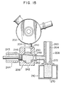
- Figure 16 shows the shaft member 229 which is arranged to rotate about its longitudinal axis L as indicated by the arrow, that is clockwise when viewed from the right hand end.
- One of the collecting blades 228 is arranged to the left of the feed opening 203 and extends perpendicular to a plane which is parallel to be flat sheet of the drawing and which includes the longiduitnal axis L.
- the collecting blade 228 forms an angle ⁇ with the longitudinal axis L of the shaft member 229, which angle ⁇ satisfies the condition 0° ⁇ ⁇ ⁇ 90°.
- the solid component of the mixture is gradually moved along the bottom surface of the mixing container 202 and transferred towards the feed opening 203 by arranging the collecting blade 228 is such a manner as described above.
- the collecting blades 2208 there may be mentioned such a screw type one as shown in Fig. 17, such a helical ribbon type one as shown in Fig. 18 and such a paddle type one as shown in Fig. 19.
- the screw type collecting blade provides various advantages: (1) it can transfer the solid component to the filling device even if the rotational speed is substantially low and (2) it is possible to restrict the occurrence of damage to the solid component since the blades, in this case, is comprised of a continuous one. If a ribbon type or paddle type collecting blade is used, it is necessary to increase the rotational speed thereof in order to achieve a desired movement or transfer of the solid component. However, these types of blades exhibit advantages in that they may easily be processed to desired shapes and thus the manufacturing cost thereof is quite low.
- the collecting blades 228 are arranged along a spiral locus at equal intervals and thus they make it possible to transfer the solid component at an equal speed over the whole portion of the mixing container 202.
- the collecting blades 228 should not be mounted on the upper portion of the feed opening 203. This is because the deposits of the solid component are disturbed in the vicinity of the feed opening 203 due to the rotation of the collecting blades 228 and thus becomes unstable.
- the chute member 204 of relatively great depth is used, it is not necessary to restrict the region at which the collecting blades 228 are disposed since the solid components are always deposited on the chute member 204 stably.
- the radius of the collecting blades 228 are determined so that the distance between the apex thereof and the internal surface of the mixing container 202 is as close as possible. This is required to ensure collection of the solid component by the collecting device 230.
- the chute member 204 is in general formed in a cylindrical shape or a funnel like shape and it may be integrally formed together with the mixing container 202 as a part thereof. If the collecting blades 228 are mounted on the shaft member 229 approximately perpendicular with respect to the latter the solid component is not paddled by the collecting blades 228 towards the upper portion of the mixing container 202 and in turn the solid component is not damaged and destroyed due to the collisions therebetween.
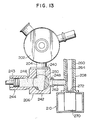
- the first piston device 206 comprises, as shown in Figs. 13 to 15, a device 242 for switching flow paths and a first piston 244 provided with a first piston member 243.
- the flow path switching device 242 is provided with an inlet portion 240, a piston communicating portion 246 and a delivery portion 248, and there is disposed a switching member 250 at the communicating portion common to these three portions.
- the switching member 250 may be located at either the position at which the inlet portion 240 and the piston communicating portion 246 are communicating with one another, as shown in Fig. 13; or the position at which the piston communicating portion 246 and the delivery portion 248 are communicating with one another as shown in Figs. 14 and 15.
- the second piston device 208 comprises a cylinder 260 provided with a tube 262 for communicating the cylinder with the delivery portion 248 of the first piston device 206.
- the position at which the communicating tube 262 is connected to the cylinder 260 is determined so that the communicating tube 262 is opened to communicate the tube 262 with the filling device 210 when a second piston member 264 is situated at the upper portion as shown in Fig. 14 and that, on the other hand, it is closed when the second piston member 264 is situated at the lower portion as shown in Figs. 13 and 15.
- the filling device 210 fills, into packing bags 270, a desired amount of the solid-liquid mixture transferred from the second piston device 208 and then seals the opening 272 of the packing bag for finishing a cycle of the packing operation of the mixture.
- the function of the apparatus for supplying solid-liquid mixture having the foregoing construction will hereunder be explained.
- the solid-liquid mixture is introduced into the mixing container 202 through the tube 226.
- the shaft member 229 is rotated at a relatively low speed to collect the solid material around the inlet portion of the chute member 204 and to deposit the solid material within the chute member 204.
- the rotational speed is determined so that the solid material does not fly about from the bottom of the container by the rotation of the shaft member 229 and it is slowly moved along the bottom surface and transferred towards the chute member 204.
- the piston member 243 of the first piston device 206 is moved back so that the inlet portion 240 and the piston communicating portion 246 communicated with one another and a desired volume for receiving the material is assured and filled by the solid-liquid mixture.
- the switching member 250 is rotated so as to communicate the piston communicating portion 246 and the delivery portion 248, as shown in Fig. 14 and thus the first piston member 243 advances to transfer, under pressure, the solid-liquid mixture present in the first piston device 206 to the second piston device 208.
- the second piston member 264 ascends to communicate the tube 262 with the packing bag 270 and thus a part of the solid-liquid mixture is packed into the packing bag 270. Then, as shown in Fig. 15, the second piston member 264 descends so that the solid-liquid mixture present in the second piston device 208 is further packed in the packing bag 270 until a desired amount of the mixture is finally filled therein.
- the adjustment of the mixing ratio of the solid-liquid mixture can be effected by selectively placing, between the chute member 204 and the inlet portion 240 in the device for switching the flow paths, a throttling plate selected from those having various openings of different sizes. Moreover, the adjustment of the mixing ratio of the solid-liquid mixture may also be effected by changing the cross-section of the flow path of the chute member 204, through which the solid material is transferred, or that of the opening 203 for feeding.
- a method of feeding a solid-liquid mixture which comprises introducing a solid-liquid mixture into a mixing container, depositing the solid component of the mixture around an opening for feeding mixture, disposed on the bottom portion of the container and feeding the mixture through the opening, it is possible to change the mixing ratio of the resultant mixture by adjusting the area of the opening for feeding. Therefore, the method exhibits a variety of advantages such that the construction thereof is very simple, the solid component is not damaged and destroyed and a desired and constant mixing ratio can certainly be maintained.
- the apparatus makes it possible to feed the solid component deposited around the opening for feeding together with the liquid component in a desired constant mixing ratio, this is because the apparatus makes it possible to adjust the mixing ratio of the mixture by simply changing the cross-section of the flow path at any position from the opening for feeding to the chute member.
Landscapes
- Engineering & Computer Science (AREA)
- Mechanical Engineering (AREA)
- Chemical & Material Sciences (AREA)
- Chemical Kinetics & Catalysis (AREA)
- Basic Packing Technique (AREA)
- Feeding, Discharge, Calcimining, Fusing, And Gas-Generation Devices (AREA)
Claims (13)
- Procédé d'alimentation d'un mélange solide-liquide constitué par au moins un composant liquide (20) et au moins un composant solide (22) de densité spécifique supérieure à celle du composant liquide, le procédé comportant les étapes qui consistent à déposer le composant solide (22) au voisinage d'une embouchure d'alimentation (203) située à la partie inférieure d'un container mélangeur (100, 202), et à alimenter le mélange solide-liquide à travers une ouverture d'alimentation vers un réceptacle (6, 210).
- Procédé selon la revendication 1, caractérisé en ce que l'alimentation du mélange solide-liquide est effectuée tout en réglant le rapport des composants du mélange en faisant varier la surface de l'ouverture (14, 42, 50, 60, 72) d'alimentation.
- Procédé selon la revendication 1, caractérisé en ce que l'alimentation du mélange solide-liquide est effectuée suivant un rapport de composants constant qui est réglé en faisant varier la section minimum du circuit d'alimentation (12, 106, 204) qui communique avec l'embouchure d'alimentation (203).
- Appareil d'alimentation d'un mélange solide-liquide comportant au moins un composant liquide (20) et au moins un composant solide (22) de densité spécifique supérieure à celle du composant liquide suivant un rapport de composants souhaité, qui comprend un container mélangeur (100, 102), une embouchure d'alimentation (203) située à la partie inférieure du container mélangeur, et un dispositif de commande de l'alimentation (4, 30, 40, 51, 61, 71) situé au-dessous ou à l'intérieur de l'embouchure d'alimentation (203), caractérisé en ce qu'il comporte en outre un dispositif collecteur (114, 230) situé dans le container mélangeur (100, 202) pour déposer le composant solide du mélange autour de l'embouchure d'alimentation (203).
- Appareil selon la revendication 4, caractérisé en ce que la surface de l'embouchure d'alimentation est réglable.
- Appareil selon les revendications 4 ou 5, caractérisé en ce que l'embouchure d'alimentation (203) communique avec l'élément de décharge (106, 204).
- Appareil selon la revendication 6, caractérisé en ce que la section droite de l'ouverture de l'élément de décharge (106, 204) est réglable.
- Appareil selon l'une quelconque des revendications 4 à 7, caractérisé en ce que le dispositif collecteur (114, 230) comporte des aubes collectrices (110, 228).
- Appareil selon la revendication 8, caractérisé en ce que chaque aube collectrice (228) est montée sur un élément d'arbre (229) et s'étend perpendiculairement au plan qui comporte l'axe longitudinal (L) de l'élément d'arbre (229) et forme un angle ϑ avec l'axe longitudinal (L) compris entre 0 degré et 90 degrés.
- Appareil selon la revendication 8, caractérisé en ce que les aubes collectrices (228) ont chacune la forme d'une vis (Figure 17).
- Appareil selon la revendication 8, caractérisé en ce que les aubes collectrices (228) ont chacune la forme d'un ruban hélicoïdal (Figure 18).
- Appareil selon la revendication 8, caractérisé en ce que les aubes collectrices (228) ont chacune la forme d'une palette (Figure 19).
- Appareil selon l'une quelconque des revendications 8 à 12, caractérisé en ce que les aubes collectrices sont situées dans des régions dont est exclue celle située juste au-dessus de l'embouchure d'alimentation (203).
Applications Claiming Priority (4)
| Application Number | Priority Date | Filing Date | Title |
|---|---|---|---|
| JP283925/86 | 1986-11-28 | ||
| JP61283925A JPS63138901A (ja) | 1986-11-28 | 1986-11-28 | 固液混合物の供給方法 |
| JP153134/87 | 1987-06-19 | ||
| JP62153134A JP2547575B2 (ja) | 1987-06-19 | 1987-06-19 | 固液混合物の供給装置 |
Publications (3)
| Publication Number | Publication Date |
|---|---|
| EP0269464A2 EP0269464A2 (fr) | 1988-06-01 |
| EP0269464A3 EP0269464A3 (en) | 1989-03-29 |
| EP0269464B1 true EP0269464B1 (fr) | 1992-08-12 |
Family
ID=26481848
Family Applications (1)
| Application Number | Title | Priority Date | Filing Date |
|---|---|---|---|
| EP87310549A Expired - Lifetime EP0269464B1 (fr) | 1986-11-28 | 1987-11-30 | Alimentation d'un mélange solide-liquide |
Country Status (5)
| Country | Link |
|---|---|
| US (1) | US4911553A (fr) |
| EP (1) | EP0269464B1 (fr) |
| KR (1) | KR910000399B1 (fr) |
| AU (1) | AU601242B2 (fr) |
| DE (1) | DE3781106T2 (fr) |
Families Citing this family (6)
| Publication number | Priority date | Publication date | Assignee | Title |
|---|---|---|---|---|
| FR2635098B1 (fr) * | 1988-08-04 | 1991-05-17 | Scoma Sa | Procede et machine pour ajouter un produit a un liquide, notamment l'ajout de ferment dans le vin |
| CH692274A5 (de) * | 1998-02-04 | 2002-04-30 | Gericke Ag | Kontinuierlicher Mischer, Mischanlage mit einem kontinuierlichen Mischer sowie Verfahren zum Betrieb einer solchen Mischanlage. |
| US8950448B2 (en) * | 2011-05-11 | 2015-02-10 | J. Clint Jameson | Multi-function transfer device |
| KR101052093B1 (ko) * | 2011-06-07 | 2011-07-26 | 이구환 | 충진제의 교반 및 공급장치 |
| CN114195072A (zh) * | 2021-12-09 | 2022-03-18 | 张家港市裕丰饮料机械有限公司 | 一种具有消泡功能的自加热式饮料灌装机 |
| CN114446034B (zh) * | 2022-04-11 | 2022-06-03 | 中国航空油料有限责任公司 | 浮动式吸油臂防碰撞预警系统及预警方法 |
Citations (2)
| Publication number | Priority date | Publication date | Assignee | Title |
|---|---|---|---|---|
| GB981332A (en) * | 1960-05-04 | 1965-01-20 | Philblack Ltd | A container for flowable material |
| US4318431A (en) * | 1980-12-08 | 1982-03-09 | Rjr Foods, Inc. | Electronic control system for a pouch packaging machine |
Family Cites Families (31)
| Publication number | Priority date | Publication date | Assignee | Title |
|---|---|---|---|---|
| US38167A (en) * | 1863-04-14 | Improvement in apparatus for stirring and mixing soaps, colors | ||
| US147717A (en) * | 1874-02-17 | Improvement in paper-pulp screens and dressers | ||
| US201410A (en) * | 1878-03-19 | Improvement in mud-pipe cleaners | ||
| US935506A (en) * | 1907-05-29 | 1909-09-28 | American Automatic Machinery Company | Filling and capping apparatus. |
| US1345657A (en) * | 1917-04-03 | 1920-07-06 | Zeuthen Anders Carl August | Method of crystallizing margarin |
| FR575666A (fr) * | 1923-03-28 | 1924-08-04 | Machine à remplir les tubes souples en étain | |
| US1640528A (en) * | 1927-04-05 | 1927-08-30 | Polysius G | Regulating discharge from containers |
| DE637290C (de) * | 1935-05-18 | 1936-10-26 | Haus Schaeben G M B H | Abfuellapparat mit Messgefaess |
| US2320469A (en) * | 1940-06-24 | 1943-06-01 | Smidth & Co As F L | Mixing and homogenizing apparatus |
| DE918010C (de) * | 1941-09-04 | 1954-09-16 | Dipl Br Ing Josef Krieglmeyer | Gegendruckflaschenfueller |
| US2362387A (en) * | 1942-05-30 | 1944-11-07 | Joseph V Ludwig | Seed planter |
| US2383536A (en) * | 1944-07-26 | 1945-08-28 | Krum Elliott Company | Dough dividing machine |
| DE826118C (de) * | 1950-08-19 | 1951-12-27 | Wenzel Herbring | Misch- und Ausgleichvorrichtung fuer Ton, Lehm und aehnliche Stoffe |
| GB714790A (en) * | 1952-03-04 | 1954-09-01 | Autopack Ltd | Automatic weighing machines |
| US2957203A (en) * | 1957-04-26 | 1960-10-25 | Mobay Chemical Corp | Process and apparatus for making plastics |
| US3029069A (en) * | 1960-05-03 | 1962-04-10 | Wilevco Inc | Mixer |
| US3148866A (en) * | 1963-07-23 | 1964-09-15 | Charles H Booth | Method of treating flue dust |
| NL128231C (fr) * | 1963-12-26 | |||
| AT265214B (de) * | 1964-12-29 | 1968-10-10 | Erich Karl Todtenhaupt | Vorrichtung zur Herstellung gleichmäßiger Dispersionen |
| US3516220A (en) * | 1965-01-11 | 1970-06-23 | Charles Gilbert Buford | Container filling apparatus |
| US3366368A (en) * | 1965-10-19 | 1968-01-30 | Johns Manville | Method for feeding particulate material |
| US4099005A (en) * | 1977-03-30 | 1978-07-04 | Olin Corporation | Apparatus and method for dispensing solids into a liquid medium |
| US4185587A (en) * | 1978-04-06 | 1980-01-29 | Chore-Time Equipment, Inc. | Hog feeder |
| US4519529A (en) * | 1979-10-22 | 1985-05-28 | King-Seeley Thermos Co. | Dispensing stopper |
| GB2091232A (en) * | 1981-01-19 | 1982-07-28 | Weatherchem Corp | Dispensing closure for containers |
| DE3103686A1 (de) * | 1981-01-30 | 1982-09-02 | Schering Ag, 1000 Berlin Und 4619 Bergkamen | Vorrichtung zur ausbringung von granulierten duengemitteln |
| GB2146617B (en) * | 1983-09-14 | 1986-11-19 | St Ivel Ltd | Cup filling apparatus |
| AU4338585A (en) * | 1984-06-06 | 1985-12-12 | Fentor Pty. Ltd. | Dispenser |
| JPH0341818Y2 (fr) * | 1984-11-30 | 1991-09-02 | ||
| US4712922A (en) * | 1986-01-03 | 1987-12-15 | Core Industries Inc. | Material mixing apparatus |
| CA1286480C (fr) * | 1986-02-28 | 1991-07-23 | Peter F. Bagatto | Methode et dispositif pour epaissir les boues rouges derivees de la bauxite, et de bouillies analogues |
-
1987
- 1987-11-25 US US07/125,441 patent/US4911553A/en not_active Expired - Fee Related
- 1987-11-27 AU AU81890/87A patent/AU601242B2/en not_active Ceased
- 1987-11-28 KR KR1019870013481A patent/KR910000399B1/ko not_active Expired
- 1987-11-30 DE DE8787310549T patent/DE3781106T2/de not_active Expired - Fee Related
- 1987-11-30 EP EP87310549A patent/EP0269464B1/fr not_active Expired - Lifetime
Patent Citations (2)
| Publication number | Priority date | Publication date | Assignee | Title |
|---|---|---|---|---|
| GB981332A (en) * | 1960-05-04 | 1965-01-20 | Philblack Ltd | A container for flowable material |
| US4318431A (en) * | 1980-12-08 | 1982-03-09 | Rjr Foods, Inc. | Electronic control system for a pouch packaging machine |
Also Published As
| Publication number | Publication date |
|---|---|
| US4911553A (en) | 1990-03-27 |
| EP0269464A3 (en) | 1989-03-29 |
| AU601242B2 (en) | 1990-09-06 |
| DE3781106D1 (de) | 1992-09-17 |
| KR880006114A (ko) | 1988-07-21 |
| AU8189087A (en) | 1988-06-02 |
| DE3781106T2 (de) | 1993-03-25 |
| EP0269464A2 (fr) | 1988-06-01 |
| KR910000399B1 (ko) | 1991-01-25 |
Similar Documents
| Publication | Publication Date | Title |
|---|---|---|
| US3490655A (en) | Material blending silo | |
| EP0269464B1 (fr) | Alimentation d'un mélange solide-liquide | |
| US7651007B2 (en) | Method of uniformly supplying a mixture of particulate solids | |
| JPS63501789A (ja) | 粉末を正確に容器に装入する方法と装置 | |
| KR20190135419A (ko) | 에스프레소 커피 머신의 포타필터에 소정의 중량을 가지며 주어진 레시피에 따른 상이한 종류의 커피로 구성된 분량의 분쇄 커피를 적재하는 기기 | |
| EP0449215B1 (fr) | Appareil pour l'amenée réglable de matériau particulaire | |
| JPH11139412A (ja) | 粉末供給源を備えたホッパから容器を充填するのを援助する装置および方法 | |
| EP0816034A1 (fr) | Appareil pour melanger et dégazer une masse écoulable | |
| US3945615A (en) | Continuous method and device for withdrawing particulate material from a container | |
| EP0705214A1 (fr) | Systemes de transport pneumatique | |
| US5413254A (en) | Vibratory feeder | |
| JP2547575B2 (ja) | 固液混合物の供給装置 | |
| US4687674A (en) | Continuous mixing process | |
| CA2188062C (fr) | Dispositif de prelevement dose de solides en vrac | |
| US3501060A (en) | Apparatus for supplying a filter-aid material | |
| US3860129A (en) | Apparatus for homogenizing particulate material | |
| CN213949415U (zh) | 一种多出口物料分配装置 | |
| US998317A (en) | Water-purifying apparatus. | |
| DE19932623A1 (de) | Entgasungseinrichtung für viskose Flüssigkeiten, wie Gießharz | |
| JPH02283226A (ja) | 自動給餌装置 | |
| US3809133A (en) | Hopper with variable level hopper feed tube | |
| CA2087178C (fr) | Melangeur avec chicane virtuelle pour substances particulaires | |
| SU1650523A2 (ru) | Машина дл укладки в банки мелкой рыбы | |
| GB2146617A (en) | Cup filling apparatus | |
| RU2186344C2 (ru) | Объемный дозатор для мучнистых продуктов |
Legal Events
| Date | Code | Title | Description |
|---|---|---|---|
| PUAI | Public reference made under article 153(3) epc to a published international application that has entered the european phase |
Free format text: ORIGINAL CODE: 0009012 |
|
| 17P | Request for examination filed |
Effective date: 19880217 |
|
| AK | Designated contracting states |
Kind code of ref document: A2 Designated state(s): CH DE FR GB IT LI NL SE |
|
| PUAL | Search report despatched |
Free format text: ORIGINAL CODE: 0009013 |
|
| AK | Designated contracting states |
Kind code of ref document: A3 Designated state(s): CH DE FR GB IT LI NL SE |
|
| 17Q | First examination report despatched |
Effective date: 19901212 |
|
| GRAA | (expected) grant |
Free format text: ORIGINAL CODE: 0009210 |
|
| ITF | It: translation for a ep patent filed | ||
| AK | Designated contracting states |
Kind code of ref document: B1 Designated state(s): CH DE FR GB IT LI NL SE |
|
| REF | Corresponds to: |
Ref document number: 3781106 Country of ref document: DE Date of ref document: 19920917 |
|
| ET | Fr: translation filed | ||
| PLBE | No opposition filed within time limit |
Free format text: ORIGINAL CODE: 0009261 |
|
| STAA | Information on the status of an ep patent application or granted ep patent |
Free format text: STATUS: NO OPPOSITION FILED WITHIN TIME LIMIT |
|
| 26N | No opposition filed | ||
| EAL | Se: european patent in force in sweden |
Ref document number: 87310549.8 |
|
| PGFP | Annual fee paid to national office [announced via postgrant information from national office to epo] |
Ref country code: SE Payment date: 20000919 Year of fee payment: 14 |
|
| PGFP | Annual fee paid to national office [announced via postgrant information from national office to epo] |
Ref country code: GB Payment date: 20001124 Year of fee payment: 14 |
|
| PGFP | Annual fee paid to national office [announced via postgrant information from national office to epo] |
Ref country code: NL Payment date: 20001130 Year of fee payment: 14 Ref country code: FR Payment date: 20001130 Year of fee payment: 14 |
|
| PGFP | Annual fee paid to national office [announced via postgrant information from national office to epo] |
Ref country code: DE Payment date: 20010131 Year of fee payment: 14 |
|
| PGFP | Annual fee paid to national office [announced via postgrant information from national office to epo] |
Ref country code: CH Payment date: 20010205 Year of fee payment: 14 |
|
| PG25 | Lapsed in a contracting state [announced via postgrant information from national office to epo] |
Ref country code: LI Free format text: LAPSE BECAUSE OF NON-PAYMENT OF DUE FEES Effective date: 20011130 Ref country code: GB Free format text: LAPSE BECAUSE OF NON-PAYMENT OF DUE FEES Effective date: 20011130 Ref country code: CH Free format text: LAPSE BECAUSE OF NON-PAYMENT OF DUE FEES Effective date: 20011130 |
|
| PG25 | Lapsed in a contracting state [announced via postgrant information from national office to epo] |
Ref country code: SE Free format text: LAPSE BECAUSE OF NON-PAYMENT OF DUE FEES Effective date: 20011201 |
|
| REG | Reference to a national code |
Ref country code: GB Ref legal event code: IF02 |
|
| PG25 | Lapsed in a contracting state [announced via postgrant information from national office to epo] |
Ref country code: NL Free format text: LAPSE BECAUSE OF NON-PAYMENT OF DUE FEES Effective date: 20020601 |
|
| PG25 | Lapsed in a contracting state [announced via postgrant information from national office to epo] |
Ref country code: DE Free format text: LAPSE BECAUSE OF NON-PAYMENT OF DUE FEES Effective date: 20020702 |
|
| REG | Reference to a national code |
Ref country code: CH Ref legal event code: PL |
|
| GBPC | Gb: european patent ceased through non-payment of renewal fee |
Effective date: 20011130 |
|
| EUG | Se: european patent has lapsed |
Ref document number: 87310549.8 |
|
| PG25 | Lapsed in a contracting state [announced via postgrant information from national office to epo] |
Ref country code: FR Free format text: LAPSE BECAUSE OF NON-PAYMENT OF DUE FEES Effective date: 20020730 |
|
| NLV4 | Nl: lapsed or anulled due to non-payment of the annual fee |
Effective date: 20020601 |
|
| REG | Reference to a national code |
Ref country code: FR Ref legal event code: ST |
|
| REG | Reference to a national code |
Ref country code: FR Ref legal event code: ST |
|
| PG25 | Lapsed in a contracting state [announced via postgrant information from national office to epo] |
Ref country code: IT Free format text: LAPSE BECAUSE OF NON-PAYMENT OF DUE FEES;WARNING: LAPSES OF ITALIAN PATENTS WITH EFFECTIVE DATE BEFORE 2007 MAY HAVE OCCURRED AT ANY TIME BEFORE 2007. THE CORRECT EFFECTIVE DATE MAY BE DIFFERENT FROM THE ONE RECORDED. Effective date: 20051130 |